Table of Contents
Advertisement
Advertisement
Table of Contents

Related Manuals for Foxconn A76GMV


Summary of Contents for Foxconn A76GMV
- Page 1 A76GMV Motherboard User’s Manual...
- Page 2 Statement: This manual is the intellectual property of Foxconn, Inc. Although the information in this manual may be changed or modified at any time, Foxconn does not obligate itself to inform the user of these changes. Trademark: All trademarks are the property of their respective owners.
-
Page 3: Declaration Of Conformity
HON HAI PRECISION INDUSTRY COMPANY LTD 66 , CHUNG SHAN RD., TU-CHENG INDUSTRIAL DISTRICT, TAIPEI HSIEN, TAIWAN, R.O.C. declares that the product Motherboard A76GMV is in conformity with (reference to the specification under which conformity is declared in accordance with 89/336 EEC-EMC Directive) ■... - Page 4 Declaration of conformity Trade Name: FOXCONN A76GMV Model Name: Responsible Party: PCE Industry Inc. Address: 458 E. Lambert Rd. Fullerton, CA 92835 Telephone: 714-738-8868 Facsimile: 714-738-8838 Equipment Classification: FCC Class B Subassembly Type of Product: Motherboard Manufacturer: HON HAI PRECISION INDUSTRY...
-
Page 5: Installation Precautions
Installation Precautions ■ Electrostatic discharge (ESD) is the sudden and momentary electric current that flows between two objects at different electrical potentials. Normally it comes out as a spark which will quickly damage your electronic equipment. Please wear an electrostatic discharge (ESD) wrist strap when handling components such as a motherboard, CPU or memory. -
Page 6: Table Of Contents
Table of Contents Chapter 1 Product Introduction Product Specifications ................2 Layout.......................4 Back Panel Connectors ................5 Chapter 2 Hardware Install Install the CPU and CPU Cooler ..............8 Install the Memory ..................10 Install an Expansion Card ..............12 Install other Internal Connectors ............13 Jumpers ....................17 Install driver and utility ................18 Chapter 3 BIOS Setup... - Page 7 Technical Support : Support Website : http://www.foxconnchannel.com Support Website : http://www.foxconnsupport.com Worldwide Online Contact Support : http://www.foxconnsupport.com/inquiry.aspx CPU Support List : http://www.foxconnsupport.com/cpusupportlist.aspx Memory, VGA Compatibility List : http://www.foxconnsupport.com/complist.aspx...
- Page 8 Thank you for buying Foxconn A76GMV motherboard. Foxconn products are engineered to maximize computing power, providing only what you need for break-through performance. With advanced overclocking capability and a range of connectivity features for today multi-media computing requirements, A76GMV enables you to unleash more power from your computer.
-
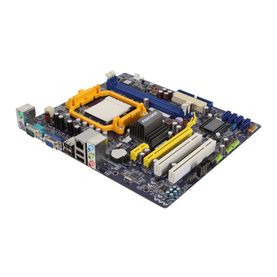
Page 9: Product Specifications
1-1 Product Specifications Support AM3 socket processors, Max processor power up to 95W For the latest CPU information, please visit: http://www.foxconnsupport.com/cpusupportlist.aspx HyperTransport Up to 4800MT/s (HT3.0) for AM3 CPU Chipset North Bridge: AMD 760G South Bridge: SB700 / SB710 Memory 2 x 240-pin DDR3 DIMMs Support up to 8GB of system memory Dual channel DDR3 1333/1066 MHz architecture... - Page 10 Internal Connectors 1 x 24-pin ATX main power connector 1 x 4-pin ATX 12V power connector 4 x SATA connectors 3 x USB 2.0 connectors (supporting 6 x USB devices) 1 x CPU fan header (4-pin) 1 x System fan header (4-pin) 1 x Front panel connector 1 x CD_IN connector 1 x Front Audio connector...
-
Page 11: Layout
1-2 Layout 12. Clear CMOS Jumper 1. 4-pin ATX 12V Power Connector 13. Speaker Connector 2. CPU_FAN Header 14. Front Panel Connector 3. North Bridge: AMD 760G 15. SATA Connectors 4. PCI Express x1 Slot 16. IDE Connector 5. PCI Express x16 Slot 17. -
Page 12: Back Panel Connectors
1-3 Back Panel Connectors PS/2 Mouse Port LAN Port Line In Line Out Microphone PS/2 Keyboard Port COM1 Port VGA Port USB Ports Audio Ports 1. PS/2 Mouse Port Use the PS/2 port (green) to connect a PS/2 mouse. 2. PS/2 Keyboard Port Use the lower port (purple) to connect a PS/2 keyboard. - Page 13 7. RJ-45 LAN Port The Ethernet LAN port provides Internet connection at up to 10/100/1000Mb/s data rate. Link Left: Active Right: Link Active LAN Type Status Description Status Description No Link No Link 10 Mb/s Connection 1000M Green Data Activity Green 100 Mb/s Connection Blinking...
- Page 14 This chapter introduces the hardware and software installation proc- ess, including the installation of the CPU, memory, power supply, slots, pin headers and the mounting of jumpers. Caution should be exercised during the installation of these modules. Please refer to the motherboard layout prior to any installation and read the contents in this chapter carefully.
-
Page 15: Install The Cpu And Cpu Cooler
2-1 Install the CPU and CPU Cooler Read the following guidelines before you begin to install the CPU: ■ Make sure that the motherboard supports the CPU. ■ Always turn off the computer and unplug the power cord from the power supply before installing the CPU to prevent hardware damage. -
Page 16: Install The Cpu Cooler
CPU socket lever back to its locked position. Install the CPU Cooler Follow the steps below to correctly install the CPU cooler. (The following procedures use Foxconn cooler as the example.) 2. Buckle the heatsink firmly at one 1. -
Page 17: Install The Memory
2-2 Install the Memory Read the following guidelines before you begin to install the memory : ■ Make sure that the motherboard supports the memory. It is recommended that memory of the same capacity, brand, speed, and chips be used. ■... -
Page 18: Installing A Memory
Installing a Memory Before installing a memory module, make sure to turn off the computer and unplug the power cord from the power outlet to prevent damage to the memory module. Be sure to install DDR3 DIMMs on this motherboard. Notch If you take a look at front side of memory module, it has asymmetric pin counts on both sides separated by a notch in the middle, so it can only fit in one direction. -
Page 19: Install An Expansion Card
2-3 Install an Expansion Card ■ Make sure the motherboard supports the expansion card. Carefully read the manual that came with your expansion card. ■ Always turn off the computer and unplug the power cord from the power outlet before installing an expansion card to prevent hardware damage. -
Page 20: Install Other Internal Connectors
2-4 Install other Internal Connectors Power Connectors This motherboard uses an ATX power supply. In order not to damage any device, make sure all the devices have been installed properly before applying the power supply. 24-pin ATX power connector : PWR1 PWR1 is the ATX power supply connector. - Page 21 Front Panel Connector : FP1 This motherboard includes one connector for connecting HDD-LED PWR-LED the front panel switch and LED Indicators. RESET-SW PWR-SW Hard Disk LED Connector (HDD-LED) EMPTY Connect to the chassis front panel IDE indicator LED. It indicates the active status of the hard disks. This 2-pin connector is directional with +/- sign.
- Page 22 Audio Connector : F_AUDIO The audio connector supports HD Audio standard. It provides the Front Audio output choice. PORT1_L AUD_GND PORT1_R PRESENCE_J PORT2_R SENSE1_RETURN SENSE_SEND EMPTY PORT2_L SENSE2_RETURN Audio Connector : CD_IN F_AUDIO CD_IN is a Sony standard audio connector, it can be connected to a CD/DVD-ROM drive through a CD/DVD audio cable.
- Page 23 Fan Connectors : CPU_FAN, SYS_FAN There are two main fan headers on this motherboard. The fan speed can be controlled and monitored in “PC POWER Health Status” section of the BIOS Setup. These fans SENSE can be automatically turned off after the system enters CONTROL S3, S4 and S5 sleeping states.
-
Page 24: Jumpers
2-5 Jumpers For some features needed, users can change the jumper settings on this motherboard to modify them. This section explains how to use the various functions of this motherboard by changing the jumper settings. Users should read the following content carefully prior to modifying any jumper setting. Description of Jumpers 1. -
Page 25: Install Driver And Utility
Only show in Windows XP system Automatic Installation by One Click Setup Drop to System Tray Exit the program View the Utility Visit Foxconn's Show Utilities Show Drivers Browse CD Help files Website Choose the items you want to Install... - Page 26 2. Utility Use these options to install additional utilities. you can click “Utility Help ” button in the main menu to view the utility(FOX ONE, FOX LiveUpdate, FOX LOGO, FOX DMI) help manual.
- Page 27 This chapter tells how to change system settings through the BIOS Setup menus. Detailed descriptions of the BIOS parameters are also provided. You have to run the Setup Program when the following cases oc- cur: 1. An error message appears on the screen during the system Power On Self Test (POST) process.
-
Page 28: Enter Bios Setup
Enter BIOS Setup The BIOS is the communication bridge between hardware and software, correctly setting up the BIOS parameters is critical to maintain optimal system performance. Power on the computer, when the message "Press <DEL> to enter Setup, <ESC> to boot menu". appears at the bottom of the screen, you can press <DEL>... - Page 29 We do not guarantee all CPU hidden Cores can be activated. If system halt or PC can not enter the Operating System, Please press and hold the Power Button until the PC powers off and restart your PC. If PC still does not work at all, it mean that this function can not be enabled.
-
Page 30: System Information
► SATA4# [Not Detected] configure system Date. Halt On [All Errors, But ...] Keyboard [Disabled] Mouse [Disabled] Model Name : A76GMV BIOS Version :A65F1D02 Memory :512MB MAC Address :00-E0-4C-68-00-04 CPU Name :AMD Phenom(tm) II X2 545 Processor ↑↓←→:Move Enter:Select +/-/:Value F10:Save... - Page 31 ► Mouse The system boot will not stop for a mouse error if you enabled this item. ► Model Name Model name of this product. ► BIOS Version It displays the current BIOS ID/version. User can check this information and discuss with the field service people if a BIOS upgrade is needed.
-
Page 32: Advanced Bios Features
Advanced BIOS Features CMOS Setup Utility - Copyright (C) 1985-2008, American Megatrends, Inc. Advanced BIOS Features IDE Detect Time Out Help Item [35] MPS Revision [1.4] PCI Latency Timer [64] Select the time out Quiet Boot [Enabled] value for detecting Quick Boot [Enabled] ATA/ATAPI device(s) -
Page 33: Core Releaser
[Disabled] : Displays the normal POST messages. [Enabled] : Displays OEM customer logo instead of POST messages. ► Quick Boot While Enabled, this option allows BIOS to skip certain tests while booting, this will shorten the time needed to boot the system. ►... -
Page 34: Fox Central Control Unit
Fox Central Control Unit CMOS Setup Utility - Copyright (C) 1985-2008, American Megatrends, Inc. Fox Central Control Unit Super BIOS Protect [Disabled] Help Item [Disabled] Auto Detect PCI Clock [Disabled] Options ► Smart BIOS [Press Enter] ► Fox Intelligent Stepping [Press Enter] ►... -
Page 35: Smart Bios
Smart BIOS CMOS Setup Utility - Copyright (C) 1985-2006, American Megatrends, Inc. Smart BIOS Smart Power LED [Disabled] [Disabled] Help Item Smart Boot Menu [Enabled] Options Disabled Enabled ↑↓←→:Move Enter:Select +/-/:Value F10:Save ESC:Exit F1:General Help F9:Optimized Defaults ► Smart Power LED Smart Power LED is a feature built on your motherboard to indicate different states during Power On Self Test (POST). -
Page 36: Fox Intelligent Stepping
Fox Intelligent Stepping CMOS Setup Utility - Copyright (C) 1985-2008, American Megatrends, Inc. Fox Intelligent Stepping CPU Clock Adjust [200] Help Item CPU Multiplier Adjust [Auto] Current CPU Speed : 3000MHz CPU-NB HT Link Speed [Auto] Current FSB/HTT Speed : 2000MHz CPU-NB Multiplier Control [Auto] Current CPU-NB Speed... -
Page 37: Spread Spectrum
► PCI Express Clock Override This option is used to adjust the speed of PCI Express slot. It may enhance the graphics card speed. ► Spread Spectrum If you enabled this function, it can significantly reduce the EMI (Electromagnetic Interference) generated by the system, so to comply with FCC regulation. -
Page 38: Cpu Configuration
CPU Configuration This menu shows most of the CPU specifications. CMOS Setup Utility - Copyright (C) 1985-2008, American Megatrends, Inc. CPU Configuration CPU Configuration Help Item Module Version : 13.70 AGESA Version : 3.7.0.1 Enable/disable the Physical Count : 1 generation of ACPI Logical Count : _PPC, _PSS, and _PCT... -
Page 39: Advanced Chipset Features
Advanced Chipset Features CMOS Setup Utility - Copyright (C) 1985-2008, American Megatrends, Inc. Advanced Chipset Features Northbridge Chipset Configuration Help Item ► Memory Configuration [Press Enter] [Press Enter] ► DRAM Timing Configuration [Press Enter] CAS Latency : N/A ,6 CLK RAS/CAS Delay : N/A ,6 CLK Row Precharge Time... -
Page 40: Memory Configuration
Memory Configuration CMOS Setup Utility - Copyright (C) 1985-2008, American Megatrends, Inc. Memory Configuration Memory Configuration Help Item Bank Interleaving [Disabled] [Disabled] Enable bank Memory Channel Interleaving [Enabled] I interleaving DCT Unganged Mode [Always] ↑↓←→:Move Enter:Select +/-/:Value F10:Save ESC:Exit F1:General Help F9:Optimized Defaults ►... -
Page 41: Dram Timing Configuration
DRAM Timing Configuration CMOS Setup Utility - Copyright (C) 1985-2008, American Megatrends, Inc. DRAM Timing Configuration DRAM Timing Configuration Help Item Options Memory Speed Mode [Auto] DRAM Timing Mode [Auto] Auto Limit Manual ↑↓←→:Move Enter:Select +/-/:Value F10:Save ESC:Exit F1:General Help F9:Optimized Defaults ►... - Page 42 Internal Graphics Config CMOS Setup Utility - Copyright (C) 1985-2008, American Megatrends, Inc. Internal Graphics Config. Internal Graphics Configuration Help Item Options [Enabled] Internal Graphics Mode UMA Frame Buffer Size [128MB] Primary Video Controller [PCI-GFXO-IGFX] Disabled Surround View [Disabled] Enabled ↑↓←→:Move Enter:Select +/-/:Value F10:Save...
-
Page 43: Integrated Peripherals
Integrated Peripherals CMOS Setup Utility - Copyright (C) 1985-2008, American Megatrends, Inc. Integrated Peripherals ► IDE Configuration [Press Enter] [Press Enter] Help Item ► USB Configuration [Press Enter] ► SuperIO Configuration [Press Enter] Configure the IDE ► Trusted Computing [Press Enter] device(s). -
Page 44: Ide Configuration
IDE Configuration CMOS Setup Utility - Copyright (C) 1985-2008, American Megatrends, Inc. IDE Configuration IDE Configuration Help Item [Enabled] Disabled:Disable the OnBoard PCI IDE Controller OnChip SATA Channel [Enabled] I IDE Controller . OnChip SATA Type [NativeIDE] Enabled:Enable both IDE Controllers. ↑↓←→:Move Enter:Select +/-/:Value F10:Save... -
Page 45: Usb Configuration
USB Configuration CMOS Setup Utility - Copyright (C) 1985-2008, American Megatrends, Inc. USB Configuration USB Configuration Help Item Options USB Devices Enabled : None Disabled OnBoard USB Controller [Enabled] [Enabled] Enabled USB 2.0 Controller [Enabled] USB 2.0 Controller Mode [High Speed] Legacy USB Support [Enabled] ↑↓←→:Move Enter:Select... -
Page 46: Trusted Computing
► Serial Port1 Address This item is used to assign the I/O address and interrupt request (IRQ) for the onboard serial port1. ► Serial Port1 Mode This item enables you to determine the transfer mode of the serial port 1. Trusted Computing CMOS Setup Utility - Copyright (C) 1985-2008, American Megatrends, Inc. -
Page 47: Power Management Setup
Power Management Setup CMOS Setup Utility - Copyright (C) 1985-2008, American Megatrends, Inc. Power Management Setup ACPI Suspend Type Help Item [S3(STR)] Energy-using Products [Enabled] Resume by LAN [Disabled] Select the ACPI Resume by PCI Card [Disabled] state used for Resume by PCIE Card [Disabled] System Suspend. - Page 48 computer before it entering STR will be saved in memory, and the computer can quickly return to previous state when the STR function wakes. ► Energy-using Products This item is used to enable/disable the EuP(Energy-using Products) feature. When enable, the suspend power of the chipset will be cut off in S5 suspend mode in order to reduce the power consumption of motherboard.
-
Page 49: Pc Health Status
PC Health Status CMOS Setup Utility - Copyright (C) 1985-2008, American Megatrends, Inc. PC Health Status Warning Temperature [Disabled] [Disabled] Help Item Shut Down Temperature [Disabled] Options Case Open Warning [Disabled] CPU Temperature(Tcontrol) C/104 System Temperature C/82 Disabled CPU Fan Speed :3183 RPM C/122 System Fan Speed... -
Page 50: Bios Security Features
BIOS Security Features CMOS Setup Utility - Copyright (C) 1985-2008, American Megatrends, Inc. BIOS Security Features Scurity Settings Help Item Supervisor Password : Not Installed Enter or change the User Password : Not Installed password. [Press Enter] Change Supervisor Password [Press Enter] ↑↓←→:Move Enter:Select +/-/:Value... -
Page 51: Chapter 4 Raid Configuration
It includes the following information : ■ RAID Introduction ■ Install SATA Hard Disks ■ RAID Configuration ■ Create RAID Driver Disk ■ Install Windows OS The RAID BIOS Setup pictures shown in this chapter are for refer- ence only, please refer to the practical screen. -
Page 52: Raid Introduction
4-1 RAID Introduction RAID 0 (Striped) RAID 0 reads and writes sectors of data interleaved among multiple drives. If any disk member fails, it affects the entire array. The disk array data capacity is equal to the number of drive mem- bers times the capacity of the smallest member. -
Page 53: Install Sata Hard Disks
4-2 Install SATA Hard Disks 1. Shut down your computer. 2. Install SATA hard disks into the drive bays. 3. Connect all the SATA power and SATA data cables. 4-3 RAID Configuration This motherboard supports RAID 0, RAID 1 and RAID10 functions. Hardware and software you may need here : ■... - Page 54 Create RAID array Here we create RAID 0 as an example: 1. Press [2] in the main menu, "Define LD Menu" appears and the "LD 1" row is highlight, press [Enter], the scree is shown as below: Option ROM Utility (c) 2008 Advanced Micro Devices, Inc. [ Define LD Menu ] [ Define LD Menu ] LD No...
-
Page 55: Create Raid Driver Disk
Delete RAID array 1. Press [3] in the Main Menu to enter the “Delete LD Menu”. 2. Highlight the array you want to delete and press [Del] or [Alt-D] keys. 3. Press [Ctrl-Y] if you are sure to delete the array or other keys to abort. Option ROM Utility (c) 2008 Advanced Micro Devices, Inc. -
Page 56: Install Windows Os
4-5 Install Windows OS Install Windows XP 1. Press [Del] during POST to enter BIOS. 2. Insert the Windows XP installation CD into the optical drive. 3. Set the “1st Boot Device” to “CD/DVD-ROM”, save changes and exit BIOS. 4. Press [F6] as soon as you see the message “Press F6 if you need to install a 3rd party SCSI or RAID driver”.
Need help?
Do you have a question about the A76GMV and is the answer not in the manual?
Questions and answers