Sign In
Upload
Download
Table of Contents
Contents
Add to my manuals
Delete from my manuals
Share
URL of this page:
HTML Link:
Bookmark this page
Add
Manual will be automatically added to "My Manuals"
Print this page
×
Bookmark added
×
Added to my manuals
Manuals
Brands
Foxconn Manuals
Motherboard
A7GMX-K
User manual
Foxconn A7GMX-K User Manual
English manual.
Hide thumbs
1
2
3
4
5
Table Of Contents
6
7
8
9
10
11
12
13
14
15
16
17
18
19
20
21
22
23
24
25
26
27
28
29
30
31
32
33
34
35
36
37
38
39
40
41
42
43
44
45
46
47
48
49
50
51
52
53
54
55
56
57
58
59
60
61
62
63
64
65
66
67
68
69
70
71
72
73
74
75
76
77
78
79
80
81
82
83
84
85
86
87
88
89
90
91
92
93
94
95
96
97
98
99
100
101
102
103
104
105
106
page
of
106
Go
/
106
Contents
Table of Contents
Bookmarks
Table of Contents
Declaration of Conformity
Installation Precautions
Table of Contents
Chapter 1 Product Introduction
Product Specifications
Layout
Back Panel Connectors
Chapter 2 Hardware Install
Install the CPU and CPU Cooler
Install the Cpu Cooler
Install the Memory
Installing a Memory
Install an Expansion Card
Install Other Internal Connectors
Jumpers
Chapter 3 BIOS Setup
Enter BIOS Setup
Main Menu
System Information
Advanced BIOS Features
Fox Central Control Unit
Fox Intelligent Stepping
Cpu Configuration
Advanced Chipset Features
Memory Configuration
Dram Timing Configuration
Integrated Peripherals
Ide Configuration
Usb Configuration
Superio Configuration
Onboard Floppy Controller
Trusted Computing
Power Management Setup
PC Health Status
BIOS Security Features
Load Optimal Defaults
Save & Exit Setup
Exit Without Saving
Chapter 4 CD Instruction
Utility CD Content
Install Driver and Utility
Fox One
Main Page
CPU Control
Frequency Control
Limit Setting
Voltage Control
Fan Control
FOX Liveupdate
Local Update
Online Update
Configure
About & Help
Fox Logo
Fox DMI
Creating a Non-Bootable Array - Existing Windows Xp (or Vista)
Chapter 5 RAID Configuration
RAID Configuration Introduction
Fastbuild Driver
Create a RAID Driver Diskette
RAID Enable in BIOS
Select a RAID Array for Use
Hard Disks
Create Raid 1 (Mirrored)
Install a New Windows XP
Setting up a Non-Bootable RAID Array
Advertisement
Quick Links
1
Product Specifications
2
Layout
3
Back Panel Connectors
4
Install the Memory
5
Install Other Internal Connectors
6
Jumpers
Download this manual
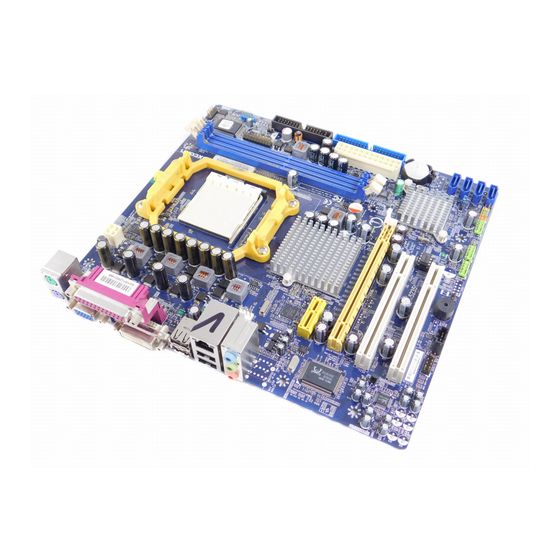
A7GMX/A7VMX Series
Motherboard
User's Manual
Table of
Contents
Previous
Page
Next
Page
1
2
3
4
5
Advertisement
Table of Contents
Need help?
Do you have a question about the A7GMX-K and is the answer not in the manual?
Ask a question
Questions and answers
Related Manuals for Foxconn A7GMX-K
Motherboard Foxconn A7GM-S User Manual
English manual. (107 pages)
Motherboard Foxconn A7GM-S 2.0 User Manual
(107 pages)
Motherboard Foxconn A7GMP-S User Manual
English manual. (105 pages)
Motherboard Foxconn A74ML Series User Manual
English manual. (105 pages)
Motherboard Foxconn A74ML 3.0 Series User Manual
English manual. (105 pages)
Motherboard Foxconn A74MX-K User Manual
English manual (105 pages)
Motherboard Foxconn A75MX Series User Manual
User manual (102 pages)
Motherboard Foxconn A75M Series User Manual
User manual (104 pages)
Motherboard Foxconn A76ML-K 3.0 User Manual
English manual. (56 pages)
Motherboard Foxconn A76ML Series User Manual
English manual. (105 pages)
Motherboard Foxconn A78AX 3.0 Series User Manual
English manual. (100 pages)
Motherboard Foxconn A78AX-K User Manual
English manual. (106 pages)
Motherboard Foxconn A79A-S User Manual
English manual. (115 pages)
Motherboard Foxconn A7DA 3.0 Series User Manual
English manual. (112 pages)
Motherboard Foxconn A7DA-S User Manual
English manual. (111 pages)
Motherboard Foxconn A7VA Series User Manual
English manual. (105 pages)
This manual is also suitable for:
A7gmx-s
A7vmx-k
A7vmx-s
A7gmx series
A7vmx series
Table of Contents
Print
Rename the bookmark
Delete bookmark?
Delete from my manuals?
Login
Sign In
OR
Sign in with Facebook
Sign in with Google
Upload manual
Upload from disk
Upload from URL


Need help?
Do you have a question about the A7GMX-K and is the answer not in the manual?
Questions and answers