Table of Contents
Advertisement
Quick Links
Download this manual
See also:
Owner's Manual
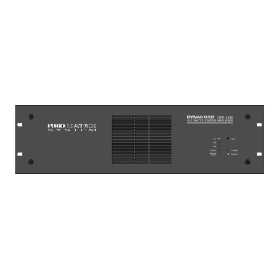
POWER AMPLIFIER DPA 4120 / DPA 4140
Performance Features
Power amplifier with 200 W or 400 W output power according to the IEC 283-3 standard within a
19" - cabinet (3 HU) providing the following functions:
supported are 115/230V AC mains as well as 24V DC emergency power source
power amplifiers DPA 4120 providing 200 W or DPA 4140 providing 400 W output power, idling and short-circuit
protection
output transformer for balanced, floating 100 V speaker networks of optionally 70 V, 50 V or
4 ohms for low-impedance operation
optional input modules:
standard operation INPUT MODULE with level control, electronically balanced input and MONITOR output with
optional transformer or
REMOTE MODULE for controlling and monitoring the PROMATRIX system, electronic level controls, electronically
balanced input and MONITOR output with optional transformer
integrated stand-by power supply
mains POWER ON/OFF switch
ground lift switch
remotely controllable mains and battery operation with initial current inrush limiter
power-on switching noise suppression
status-LED indicators for operation (READY), STANDBY, thermal overload (PROTECT) and
occurrence of GROUND FAULT conditions at the power output
fault message according to the IEC 849 standard
TEST button to switch between system and average operation, respectively a RESET button to restart after the
occurrence of ground fault conditions
LED level meter instrument with a display range of -13 dB to 0 dB and CLIP
integrated relays for single call and obligatory reception
active, temperature controlled ventilation
pilot tone and ground fault surveillance module according to the DIN/VDE 0800 standard (optional)
40 0 WATT S POWER AMPL IF IER
23
OWNER'S MANUAL
DPA 4140
CLIP
T EST
0dB
- 13dB
READY
STANDBY
GR OUND
PR OT ECT
FAULT
Advertisement
Table of Contents

Related Manuals for Dynacord DPA 4120


Summary of Contents for Dynacord DPA 4120
- Page 1 19“ - cabinet (3 HU) providing the following functions: supported are 115/230V AC mains as well as 24V DC emergency power source power amplifiers DPA 4120 providing 200 W or DPA 4140 providing 400 W output power, idling and short-circuit protection...
-
Page 3: Indicators, Controls And Connections
Indicators, controls and connections DPA 4140 4 0 0 WATT S PO WE R AM P L IFI ER C L IP TES T 0 d B -1 3 d B R EAD Y STAN DBY G RO UN D PR OTE CT FAUL T T4A FOR 230V... -
Page 4: Table Of Contents
13.4 NRS 90227 output transformer for floating, balanced monitor output ..........44 13.5 NRS 90224 pilot tone and ground fault surveillance................ 44 Block diagrams ..........................67 14.1 Power amplifiers DPA 4120 / DPA 4140 ..................67 14.2 NRS 90225 general input module....................68... -
Page 5: Utilization
The amplifiers DPA 4120 and DPA 4140 are specially designed for the power-consistent and reliable operation of PA- systems. The DPA 4120 and DPA 4140 are intended to be used in company intercom, alarm and background music transmission installations, offices and commercial areas, congregation and sport centers, schools, churches, hotels, hospitals, shopping malls and super markets, cruise ships, and other similar applications. -
Page 6: Battery Operation 24V Dc
(see also paragraph 6.2). Battery operation 24V DC The amplifiers, DPA 4120 and DPA 4140, use the mains or alternatively an external 24V battery as power source. Switching to battery is performed via integrated relays. The battery has to be connected on the rear of the amplifiers (20) using insulated 6.3x0.8 mm AMP flat plug connectors. -
Page 7: Outputs
Connection has to be performed by inserting the supplied 5-pole plug into the power output socket (17). Switching the output voltage to 70V, 50V or to low impedance operation (4 ohms) is possible using the plug-in bridge B411 on the printed board assembly 84187 (DPA 4120) respectively 84175 (DPA 4140) (see also paragraph 7). -
Page 8: Single Call And Obligatory Reception Relays Override Bypass
NRS 90227 (please also refer to paragraph 8.4). Note: Functioning changes in the models DPA 4120 (starting with serial numbers: 100 11) and DPA 4140 (starting with serial numbers: 100 11) in association with the input module NRS 90225: To achieve reliable attenuation of switching noise (knacks), the monitor output stays muted as long as the READY-relay is not pulled. -
Page 9: Standby Indicator
(4) will light. READY indicator Both amplifiers, the DPA 4120 and the DPA 4140, employ power-on switching delays of approximately 3 sec. to effectively eliminate power-on switching noise. After this time, the green READY indicator (7) lights and the READY fault message relay picks up when no error is being detected. -
Page 10: Enhanced Application Field
The input module is meant to be used with the power amplifiers DPA 4120 and DPA 4140. The module allows to control and monitor the operation of the power amplifiers using conventional equipment or (with reservations) by the PROMATRIX manager DPM 4000. -
Page 11: Remote Module Nrs 90222
Because of circuit design reasons this causes that the monitor output is also muted even when a ground-fault appears at the main output. Remote module NRS 90222 This input and remote module for the power amplifiers DPA 4120 and DPA 4140 is meant for insertion at the power amplifiers' rear. It provides the following functions: •... -
Page 12: Nrs 90227 Output Transformer For The Floating, Balanced Monitor Output
- re-insert the input module and tighten the locking screws (B). NRS 90227 output transformer for the floating, balanced monitor output In case that floating monitor outputs are required, the outputs of the INPUT MODULE NRS 90225 and REMOTE MODULE NRS 90222 are prepared for retrofitting output transformers. If so, it is necessary to additionally install the extension kit NRS 90227 per each output. -
Page 13: Nrs 90224 Pilot Tone And Ground Fault Surveillance
Output Transformer NRS 90227 figure 6 printed board assembly 81338 showing the input transformer NRS 90208 and the output transformer NRS 90 227 Input Transformer NRS 90208 Output Transformer 90 227 figure 7 printed board assembly 81339 showing the input transformer NRS 90208 and the output transformer NRS 90 227 NRS 90224 pilot tone &... - Page 14 When off-ground potential loudspeaker cable networks are employed we recommend insulation-monitoring using the ground fault surveillance module NRS 90224. Error recognition: An occurring ground fault either signals that one of the cables is damaged - which most likely point towards a total line interruption in the near future - or that connections have been carried out erroneously which may lead to malfunctioning of the entire system.
- Page 15 B 411 figure 8 printed board assembly 84187 in the DPA 4120 showing the NRS 90224 pilot tone & ground fault surveillance and the bridges B411 and S405, S406 for switching the output voltage; inserted...
- Page 16 NRS 90 224 S 406 S 405 B 411 figure 9 printed board assembly 84175 in the DPA 4140 showing the NRS 90224 pilot tone & ground fault surveillance and the bridges B411 and S405, S406 for switching the output voltage; inserted Checking the pilot tone surveillance function: When the NRS 90224 is installed and the power amplifier is switched on, the green READY indicator (7) has to light.
-
Page 17: Case And 19"-Rack Shelf System Installation
19"-case and 19“-rack-shelf system installation Note Operation of the power amplifiers DPA 4120 and DPA 4140 with enclosure cover plates detached is strictly prohibited. When mounting the power amplifiers within rack-cases or rack-shelf systems make sure to provide sufficient airflow. - Page 18 F 503 F 502 figure 10 printed board assembly 85270 in the DPA 4120 showing the DC fuses F502 and F503...
- Page 19 F 503 F 502 figure 11 printed board assembly 85268 in the DPA 4140 showing the DC fuses F502 and F503...
- Page 20 Replacing the fuses F502 and F503 (only to be carried out by the experienced service technician!) The battery fuses F502 and F503 are located on the power supply PCBs 85270 (DPA 4120) and 85268 (DPA 4140) behind the AMP battery connectors (see also figure 10 and/or figure 11). To replace these fuses you have to remove the cover plate of the appliance and afterwards the power supply input PCB 86243 which is mounted to the rear panel of the appliance.
-
Page 21: Dpa 4120 Power Amplifier 200 W
PCB are within a distance of at least 6 mm to the printed board assembly. Specifications 12.1 DPA 4120 power amplifier 200 W power supply: mains operation 115 V / 230 V~ AC, ±10 %... -
Page 22: 12.2 Dpa 4140 Power Amplifier 400 W
ambient temperature range +5 °C .. +40 °C dimensions (W x H x D) 483 x 132 x 345 mm depth with / without connections max. 400 mm / max. 340 mm weight without extensions 13.2 kg finish anthracite 12.2 DPA 4140 power amplifier 400 W power supply: mains operation 115 V / 230 V~ AC,... -
Page 23: Nrs 90222 Remote Module
Art. No. 121 677 NRS 90227 output transformer for floating, balanced monitor output Art. No. 121 679 Extension kit specifications for the power amplifiers DPA 4120 / DPA 4140 13.1 NRS 90225 standard input module see specifications DPA 4120 / DPA 4140 13.2...
Need help?
Do you have a question about the DPA 4120 and is the answer not in the manual?
Questions and answers