
Subscribe to Our Youtube Channel
Related Manuals for MiLAN MIL-SM4804G


Summary of Contents for MiLAN MIL-SM4804G
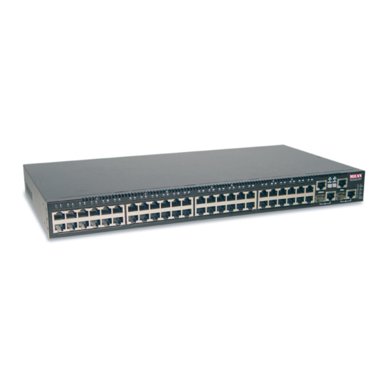
- Page 1 48 10/100 Ports + 2 Combo SFP Gigabit Ports + 2 10/100/1000 Gigabit Ports Multi-Layer Stackable Management Switch MIL-SM4804G Quick Installation Guide...
- Page 3 Quick Installation Guide 48 10/100 Ports + 2Combo SFP + 2 Gigabit Copper Multi-Layer Stackable Management Switch Layer 2 Stackable Switch with 50 100BASE-TX (RJ-45) Ports, and 2 Gigabit Combination Ports (RJ-45/SFP)
- Page 4 MIL-SM4804G 90000444 REV A...
- Page 5 MiLAN Technology makes no express or implied warranties including, but not lim- ited to, any implied warranty of merchantability or fitness for a particular purpose, except as expressly set forth in this warranty. In no event shall MiLAN Technology be liable for incidental or consequential damages, costs, or expenses arising out of or in connection with the performance of the product delivered hereunder.
- Page 6 Trademarks The MiLAN logo and MiLAN Technology trademarks are registered trademarks of MiLAN Technology in the United States and/or other countries. To Contact MiLAN Technology For prompt response when calling for service information, have the following infor- mation ready: - Product serial number and revision...
-
Page 7: Compliances And Safety Warnings
Compliances and Safety Warnings CE Mark Declaration of Conformance for EMI and Safety (EEC) This information technology equipment complies with the requirements of the Council Directive 89/336/EEC on the Approximation of the laws of the Member States relating to Electromagnetic Compatibility and 73/23/EEC for electrical equipment used within certain voltage limits and the Amendment Directive 93/68/EEC. -
Page 8: Installing The Switch
Faserkabelenden schauen, während diese eingeschaltet sind. Please read the following safety information carefully before installing the switch: WARNING: Installation and removal of the unit must be carried out by qualified personnel only. • The unit must be connected to an earthed (grounded) outlet to comply with international safety standards. - Page 9 HO3VVF3GO.75 (minimum). IEC-320 receptacle. Veuillez lire à fond l'information de la sécurité suivante avant d'installer le Switch: AVERTISSEMENT: L’installation et la dépose de ce groupe doivent être confiés à un personnel qualifié. • Ne branchez pas votre appareil sur une prise secteur (alimentation électrique) lorsqu'il n'y a pas de connexion de mise à...
- Page 10 France et Pérou uniquement: Ce groupe ne peut pas être alimenté par un dispositif à impédance à la terre. Si vos alimentations sont du type impédance à la terre, ce groupe doit être alimenté par une tension de 230 V (2 P+T) par le biais d’un transformateur d’isolement à rapport 1:1, avec un point secondaire de connexion portant l’appellation Neutre et avec raccordement direct à...
-
Page 11: Warnings And Cautionary Messages
Warning: This switch uses lasers to transmit signals over fiber optic cable. The lasers are compliant with the requirements of a Class 1 Laser Product and are inherently eye safe in normal operation. However, you should never look directly at a transmit port when it is powered on. -
Page 12: Manufacturing Materials
The following publication gives specific information on how to operate and use the management functions of the switch: The Stackable Fast Ethernet Switch Management Guide Also, as part of the switch’s firmware, there is an online web-based help that describes all management related features. viii... -
Page 13: Table Of Contents
Introduction to Switching Application Examples Collapsed Backbone Network Aggregation Plan Remote Connections with Fiber Cable Making VLAN Connections Application Notes Chapter 3: Installing the Switch Selecting a Site Ethernet Cabling Equipment Checklist Package Contents Optional Rack-Mounting Equipment Mounting Rack Mounting... - Page 14 1000 Mbps Gigabit Ethernet Collision Domain 100 Mbps Fast Ethernet Collision Domain 10 Mbps Ethernet Collision Domain Cable Labeling and Connection Records Appendix A: Troubleshooting A-1 Diagnosing Switch Indicators Diagnosing Power Problems with the LEDs Power and Cooling Problems Installation In-Band Access...
- Page 15 Tables Table 1-1 Port Status LEDs Table 1-2 System Status LEDs Table 3-1 Serial Cable Wiring Table 4-1 Maximum 1000BASE-T Gigabit Ethernet Cable Length Table 4-2 Maximum 1000BASE-SX Gigabit Ethernet Cable Lengths Table 4-3 Maximum 1000BASE-LX Gigabit Ethernet Cable Length Table 4-4 Maximum 1000BASE-LH Gigabit Ethernet Cable Length Table 4-5...
- Page 16 Making VLAN Connections Figure 3-1 RJ-45 Connections Figure 3-2 Attaching the Brackets Figure 3-3 Installing the Switch in a Rack Figure 3-4 Attaching the Adhesive Feet Figure 3-5 Installing an SFP Transceiver into a slot Figure 3-6 Connecting Switches in a Ring-topology Stack...
-
Page 17: Chapter 1: Introduction
Small Form Factor Pluggable (SFP) transceiver slots. These switches also provide two 1 Gbps built-in stacking ports for connecting up to four MIL-SM4804G units in a stack. The stacking ports can also be used as normal Ethernet ports in standalone mode. -
Page 18: Switch Architecture
2. Non-blocking switching is used for traffic crossing ports attached to the same switch ASIC; while blocking is employed for traffic passing between different switch chips. The MIL-SM4804G has two switch chips – ASIC#1: Ports 1-12, 25-36, 49, 51 and ASIC#2: Ports 13-24, 37-48, 50, 52. -
Page 19: Figure
(See “1000BASE-T Pin Assignments” on page B-3.) 3. Flow control is only supported for ports attached to the same switch ASIC. The MIL-SM4804G has two switch chips– ASIC#1: Ports 1-12, 25-36, 49, 51 and ASIC#2: Ports 13-24, 37-48, 50,... -
Page 20: Stacking Ports
Stacking Ports The unit provides two stacking ports that provide a 4 Gbps stack backplane connection. You can stack up to four MIL-SM4804G units using Category 5 Ethernet cables (purchased separately). The Master button enables one switch in the stack to be selected as the master. -
Page 21: Port And System Status Leds
Port and System Status LEDs The MIL-SM4804G includes a display panel for key system and port indications that simplify installation and network troubleshooting. The LEDs, which are located on the front panel for easy viewing, are shown below and described in the following tables. -
Page 22: Table 1-2 System Status Leds
There is no redundant power supply currently attached. An initial power-on state during which the stack configuration is detected. This switch is acting as the Master unit in the stack. This switch is acting as a Slave unit in the stack. Switch is operating in standalone mode. -
Page 23: Power Supply Receptacles
12V 4.5A Features and Benefits Connectivity • 48 (MIL-SM4804G) 100BASE-TX ports, 2 1000BASE-T ports, and 2 combination 1000BASE-T/SFP ports for easy integration and for protection of your investment in legacy LAN equipment. • Auto-negotiation enables each RJ-45 port to automatically select the optimum speed (10, 100 or 1000 Mbps), and the communication mode (half or full duplex) if this feature is supported by the attached device;... -
Page 24: Performance
Introduction Performance • Transparent bridging • Aggregate duplex bandwidth of 17.6 Gbps (MIL-SM4804G) • Switching table with a total of 8K MAC address entries • Provides store-and-forward switching • Wire-speed filtering and forwarding • Supports flow control, using back pressure for half duplex and IEEE 802.3x for full duplex •... -
Page 25: Figure
When networks are based on repeater (hub) technology, the distance between end stations is limited by a maximum hop count. However, a switch turns the hop count back to zero. So subdividing the network into smaller and more manageable segments, and linking them to the larger network by means of a switch, removes this limitation. -
Page 26: Application Examples
Network Planning Application Examples The MIL-SM4804G switch is not only designed to segment your network, but also to provide a wide range of options in setting up network connections. Some typical applications are described below. Collapsed Backbone The MIL-SM4804G is an excellent choice for mixed Ethernet, Fast Ethernet, and Gigabit Ethernet installations where significant growth is expected in the near future. -
Page 27: Network Aggregation Plan
You can stack up to four MIL-SM4804G switch units together, forming a single “virtual” switch containing up to 200 ports. The whole stack can be managed through the Master unit using a single IP address. -
Page 28: Remote Connections With Fiber Cable
1000BASE-SX (MMF) link can connect to a site up to 550 meters away, a 1000BASE-LX (SMF) link up to 5 km, and a 1000BASE-LH link up to 70 km. This allows a Gigabit Ethernet Switch to serve as a collapsed backbone, providing direct connectivity for a widespread LAN. -
Page 29: Making Vlan Connections
VLANs assigned to the inter-switch links. R&D VLAN 1 Tagged Ports Finance VLAN 2 Testing VLAN 3 Note: When connecting to a switch that does not support IEEE 802.1Q VLAN tags, use untagged ports. Untagged Ports VLAN unaware switch Marketing Finance VLAN 4... -
Page 30: Application Notes
Application Notes Full-duplex operation only applies to point-to-point access (such as when a switch is attached to a workstation, server or another switch). When the switch is connected to a hub, both devices must operate in half-duplex mode. Avoid using flow control on a port connected to a hub unless it is actually required to solve a problem. -
Page 31: Chapter 3: Installing The Switch
- be at the center of all the devices you want to link and near a power outlet. - be able to maintain its temperature within 0 to 50 °C (32 to 122 °F) for the MIL-SM4804G, and its humidity within 5% to 95%, non-condensing... -
Page 32: Equipment Checklist
Installing the Switch Equipment Checklist After unpacking this switch, check the contents to be sure you have received all the components. Then, before beginning the installation, be sure you have all other necessary installation equipment. Package Contents • Stackable Fast Ethernet Switch (MIL-SM4804G) •... -
Page 33: Mounting
Mounting This switch can be mounted in a standard 19-inch equipment rack or on a desktop or shelf. Mounting instructions for each type of site follow. Rack Mounting Before rack mounting the switch, pay particular attention to the following factors: •... -
Page 34: Figure 3-3 Installing The Switch In A Rack
Mount the device in the rack, using four rack-mounting screws (not provided). Figure 3-3 Installing the Switch in a Rack If installing a single switch only, turn to “Connecting to a Power Source” at the end of this chapter. If installing multiple switches, mount them in the rack, one below the other, in any order. -
Page 35: Desktop Or Shelf Mounting
2. Befestigen Sie das Gerät mit vier Rackmontageschrauben (nicht beigelegt) an dem Rack. 3. Wenn Sie nur einen Switch installieren, dann springen Sie bitte über zu "Verbinden mit einer Stromquelle" auf Seite 3-8 am Ende dieses Kapitels. 4. Wenn Sie mehrere Switches installieren möchten, dann montieren Sie sie untereinander in einer beliebigen Reihenfolge. -
Page 36: Installing An Optional Sfp Transceiver
Slide the SFP transceiver into the slot until it clicks into place. Note: SFP transceivers are hot-swappable. The switch does not need to be powered off before installing or removing a transceiver. However, always first disconnect the network cable before removing a transceiver. -
Page 37: Figure 3-6 Connecting Switches In A Ring-Topology Stack
You can form a stack containing up to four MIL-SM4804G units. To connect switches in a stack, perform the following steps: Enable the stacking ports on each unit (i.e., the Stack button pushed out) Note: Pressing the Stack button during normal operation will cause the system to reboot. -
Page 38: Connecting To A Power Source
Select the Master unit in the stack by pressing in the Master button on only one of the switches. Only one switch in the stack can operate as the Master, all other units operate in slave mode. If more than one switch in the stack is selected as Master, or if no switches are selected, the stack will not function. -
Page 39: Connecting To The Console Port
Connecting to the Console Port The DB-9 serial port on the switch’s back panel is used to connect to the switch for out-of-band console configuration. The command-line-driven configuration program can be accessed from a terminal or a PC running a terminal emulation program. The pin assignments used to connect to the serial port are provided in the following table. - Page 40 Installing the Switch 3-10...
-
Page 41: Chapter 4: Making Network Connections
(PCs, servers, switches, routers, or hubs). See Appendix B for further information on cabling. Caution: Do not plug a phone jack connector into an RJ-45 port. This will damage the switch. Use only twisted-pair cables with RJ-45 connectors that conform to FCC standards. -
Page 42: Connecting To Pcs, Servers, Hubs And Switches
Figure 4-1 Making Twisted-Pair Connections If the device is a network card and the switch is in the wiring closet, attach the other end of the cable segment to a modular wall outlet that is connected to the wiring closet. (See the section “Network Wiring Connections.”) Otherwise, attach the other end to an available port on the switch. -
Page 43: Figure 4-2 Network Wiring Connections
Label the cables to simplify future troubleshooting. See “Cable Labeling and Connection Records” on page 4-7. Switch Figure 4-2 Network Wiring Connections Twisted-Pair Devices Equipment Rack (side view) Punch-Down Block Patch Panel Wall... -
Page 44: Fiber Optic Sfp Devices
62.5/125 micron multimode fiber optic cabling with an LC connector at both ends. Warning: This switch uses lasers to transmit signals over fiber optic cable. The lasers are compliant with the requirements of a Class 1 Laser Product and are inherently eye safe in normal operation. -
Page 45: Connectivity Rules
Connect one end of the cable to the LC port on the switch and the other end to the LC port on the other device. Since LC connectors are keyed, the cable can be attached in only one orientation. Figure 4-3 Making Fiber Port Connections As a connection is made, check the Link LED on the switch corresponding to the port to be sure that the connection is valid. -
Page 46: 1000 Mbps Gigabit Ethernet Collision Domain
Making Network Connections Category 5 cabling for running 1000BASE-T is a simple test of the cable installation to be sure that it complies with the IEEE 802.3-2002 standards. 1000 Mbps Gigabit Ethernet Collision Domain Table 4-1 Maximum 1000BASE-T Gigabit Ethernet Cable Length Cable Type Category 5, 5e, or 6 100-ohm UTP or STP 100 m (328 ft) Table 4-2 Maximum 1000BASE-SX Gigabit Ethernet Cable Lengths... -
Page 47: Cable Labeling And Connection Records
For each piece of equipment, identify the devices to which it is connected. • Note the length of each cable and the maximum cable length supported by the switch ports. • For ease of understanding, use a location-based key when assigning prefixes to your cable labeling. - Page 48 Making Network Connections...
-
Page 49: Appendix A: Troubleshooting
• Be sure the cable is plugged into both the switch and corresponding device. • If the switch is installed in a rack, check the connections to the punch-down block and patch panel. • Verify that the proper cable type is used and its length does not exceed specified limits. -
Page 50: Power And Cooling Problems
IP address. Also, be sure the port through which you are connecting to the switch has not been disabled. If it has not been disabled, then check the network cabling that runs between your remote location and the switch. -
Page 51: Appendix B: Cables
In straight-through cable, pins 1, 2, 3, and 6, at one end of the cable, are connected straight through to pins 1, 2, 3, and 6 at the other end of the cable. When using any RJ-45 port on this switch, you can use either straight-through or crossover cable. -
Page 52: Straight-Through Wiring
If the twisted-pair cable is to join two ports and only one of the ports has an internal crossover (MDI-X), the two pairs of wires must be straight-through. (When auto-negotiation is enabled for any RJ-45 port on this switch, you can use either straight-through or crossover cable to connect to any device type.) You must connect all four wire pairs as shown in the following diagram to support Gigabit Ethernet. -
Page 53: 1000Base-T Pin Assignments
You must connect all four wire pairs as shown in the following diagram to support Gigabit Ethernet. EIA/TIA 568B RJ-45 Wiring Standard End A 1000BASE-T Pin Assignments All 1000BASE-T ports support automatic MDI/MDI-X operation, so you can use straight-through cables for all network connections to PCs or servers, or to other switches or hubs. -
Page 54: Fiber Standards
Cables Cable Testing for Existing Category 5 Cable Installed Category 5 cabling must pass tests for Attenuation, Near-End Crosstalk (NEXT), and Far-End Crosstalk (FEXT). This cable testing information is specified in the ANSI/TIA/EIA-TSB-67 standard. Additionally, cables must also pass test parameters for Return Loss and Equal-Level Far-End Crosstalk (ELFEXT). -
Page 55: Appendix C: Specifications
Appendix C: Specifications Physical Characteristics Ports 48 10/100BASE-TX, with auto-negotiation Two 10/100/1000BASE-T shared with two SFP transceiver slots Two 10/100/1000BASE-T or Stacking Ports (button selection) Network Interface Ports 1-48: RJ-45 connector, auto MDI/X 10BASE-T: RJ-45 (100-ohm, UTP cable; Category 3 or better) 100BASE-TX: RJ-45 (100-ohm, UTP cable;... -
Page 56: Switch Features
External, supports a 14-pin connection for a redundant power supply Power Consumption 54 Watts maximum Maximum Current 2.0 A @ 100 VAC 1.0 A @ 240 VAC Switch Features Forwarding Mode Store-and-forward Throughput Wire speed Flow Control Full Duplex: IEEE 802.3x... -
Page 57: Standards
Standards IEEE 802.3-2002 Ethernet, Fast Ethernet, Gigabit Ethernet Full-duplex flow control Link Aggregation Control Protocol IEEE 802.1D Spanning Tree Protocol IEEE 802.1w Rapid Spanning Tree Protocol IEEE 802.1X Port Access Authentication IEEE 802.1Q VLANs ISO/IEC 8802-3 Compliances Emissions Industry Canada Class A EN55022 (CISPR 22) Class A EN 61000-3-2/3 FCC Class A... - Page 58 Specifications...
-
Page 59: Glossary
Glossary 10BASE-T IEEE 802.3 specification for 10 Mbps Ethernet over two pairs of Category 3, 4, or 5 UTP cable. 100BASE-FX IEEE 802.3 specification for 100 Mbps Ethernet over two strands of 50/125, 62.5/ 125 micron, or 9/125 micron core fiber cable. 100BASE-TX IEEE 802.3u specification for 100 Mbps Ethernet over two pairs of Category 5 UTP cable. - Page 60 Glossary Collision A condition in which packets transmitted over the cable interfere with each other. Their interference makes both signals unintelligible. Collision Domain Single CSMA/CD LAN segment. CSMA/CD CSMA/CD (Carrier Sense Multiple Access/Collision Detect) is the communication method employed by Ethernet, Fast Ethernet, and Gigabit Ethernet. End Station A workstation, server, or other device that does not forward traffic.
- Page 61 Glossary IEEE 802.3u Defines CSMA/CD access method and physical layer specifications for 100BASE-TX Fast Ethernet. (Now incorporated in IEEE 802.3-2002.) IEEE 802.3x Defines Ethernet frame start/stop requests and timers used for flow control on full-duplex links. (Now incorporated in IEEE 802.3-2002.) IEEE 802.3z Defines CSMA/CD access method and physical layer specifications for 1000BASE Gigabit Ethernet.
- Page 62 Glossary RJ-45 Connector A connector for twisted-pair wiring. Switched Ports Ports that are on separate collision domains or LAN segments. Telecommunications Industry Association Transmission Control Protocol/Internet Protocol (TCP/IP) Protocol suite that includes TCP as the primary transport protocol, and IP as the network layer protocol.
-
Page 63: Index
Gigabit Ethernet cable lengths 4-6 grounding for racks 3-3 IEEE 802.3x flow control 1-3 indicators, LED 1-5 installation connecting devices to the switch 4-2 desktop or shelf mounting 3-5 network wiring connections 4-2 port connections 4-1, 4-4 power requirements 3-1... - Page 64 DB-9 3-9 port saturation 1-3 ports, connecting to 4-1, 4-4 power, connecting to 3-8 Index-2 problems, troubleshooting A-1 rack mounting 3-3 rear panel of switch 1-1 rear panel receptacles 1-7 RJ-45 port connections 4-1 pinouts B-3 RMON 1-2 RS-232 port 1-2...
- Page 65 Index VLANs tagging 2-5 web-based management 1-2 Index-3...
- Page 66 Index Index-4...
- Page 68 MIL-SM4804G 90000444 REV A...
Need help?
Do you have a question about the MIL-SM4804G and is the answer not in the manual?
Questions and answers