Table of Contents
Advertisement
Advertisement
Table of Contents

Related Manuals for DigiDesign Command 8


Summary of Contents for DigiDesign Command 8
- Page 1 Command|8 ™ Version 8.0...
- Page 2 Legal Notices This guide is copyrighted ©2008 by Digidesign, a division of Avid Technology, Inc. (hereafter “Digidesign”), with all rights reserved. Under copyright laws, this guide may not be duplicated in whole or in part without the written consent of Digidesign.
- Page 3 • Connect the equipment into an outlet on a circuit different from that to which the receiver is connected. • Consult the dealer or an experienced radio/TV technician for help. Any modifications to the unit, unless expressly approved by Digidesign, could void the user's authority to operate the equipment.
-
Page 5: Table Of Contents
About www.digidesign.com ........ - Page 6 Control Room Monitor Controls ..........27 Modifier Switches .
-
Page 7: Chapter 1. Introduction
Pro Tools|HD , Pro Tools LE , and level, send pan, and record status, as well as Pro Tools M-Powered™ systems, and supported PRE™ (Digidesign mic preamplifier) gain ® Avid systems. • Fast and convenient access to sends, inserts,... -
Page 8: What's Included
For complete system requirements and a list of commands: Digidesign-qualified computers, operating sys- tems, hard drives, and third-party devices, refer Convention Action to the latest information on the Digidesign web- File > Save Choose Save from the File site: menu www.digidesign.com/compatibility... -
Page 9: About Www.digidesign.com
Digidesign guides. News and Events Get the latest news from Digidesign or sign up for a Pro Tools demo. Pro Tools Accelerated Videos Watch the series of free tutorial videos. Accelerated Videos are de- signed to help you get up and running with Pro Tools and its plug-ins. - Page 10 Command|8 Guide...
-
Page 11: Chapter 2. Installing And Configuring Command|8
chapter 2 Installing and Configuring Command|8 • Command|8 must be the only MIDI control Installation Guidelines surface enabled within Pro Tools. It cannot be used in combination with other MIDI control • Pro Tools software includes drivers for surfaces. Command|8. Make sure Pro Tools is correctly installed and operating before using Com- •... -
Page 12: Example Setups
Example Setups Command|8 with Pro Tools Figure 1 shows Command|8 connected for use with Pro Tools, acting as a control surface, MIDI inter- face, and monitor controller. MIDI sound module main monitors MIDI in/out MIDI synth audio in/out headphones USB to computer Pro Tools CD player Figure 1. - Page 13 Figure 2. 003 and Command|8 fader mapping Ethernet Control Surfaces and Command|8 Command|8 can be used as a remote transport control for isolation rooms, drum booths, and other locations, or for remote control of play and record functions. When used with a Digidesign Ethernet ® ®...
-
Page 14: Command|8 Back Panel
Command|8 Back Panel Figure 4 shows the Command|8 back panel connectors and switches. Punch In +4/–10 switches Power MIDI In socket Ext Source Main Speaker MIDI Out Power Monitor Monitor switch Outputs 1 & 2 Inputs Inputs Figure 4. Command|8 back panel “Connecting Analog Audio for Monitoring”... -
Page 15: Installing Software For Command|8
Command|8 in Stand-Alone mode with your unit. Additional power supplies are Mac computers. available from your Digidesign dealer. Mac Software for Command|8 Plug the power supply into an available AC power outlet. To install Command|8 software on Mac:... -
Page 16: Connecting Analog Audio For Monitoring
Command|8 was installed automatically. The Pro Tools Installer creates a Command8 folder in your Digidesign direc- If you installed Pro Tools and did not select this tory. This folder contains copies of all the option, use your Pro Tools Installer disc to in- software you need to reinstall Command|8. - Page 17 Monitoring Overview Output Connections Command|8 provides the following analog au- To connect Command|8 to your monitoring dio connectors. system: Be sure to mute, turn down, or power off your Input monitors or monitoring system. • Two pairs of balanced, TRS inputs, labeled On the Command|8 top surface, turn the Con- Main and Ext Source on the back panel of trol Room Level knob all the way down.
-
Page 18: Connecting A Footswitch
Connect MIDI Out 2 of Command|8 to the Connecting a Footswitch MIDI In port of an additional MIDI device (such as a sound module). (Optional) To monitor or record the audio output of your The Punch In connector on the Command|8 MIDI devices within Pro Tools, connect the au- back panel supports footswitch control of Track- dio outputs of your devices to available audio in-... - Page 19 The following table shows how AMS lists Com- Configuring MIDI Studio Setup mand|8 MIDI ports: (Windows Only) Command|8 port equivalents in AMS On Windows systems, use MIDI Studio Setup to AMS (in/out) Command|8 back panel ports configure MIDI communication with Com- mand|8.
-
Page 20: Enabling Command|8 In Pro Tools
To enable Command|8 in Pro Tools: The following example shows how to configure Make sure your computer, Pro Tools hardware, Pro Tools to integrate a Digidesign PRE con- and Command|8 are powered on and operating nected to Command|8 MIDI ports. -
Page 21: Communication Test
From the Receive From menu, choose the Enabling Command|8 as an Input PRE’s source port and MIDI channel to receive Device data. It is important to choose the correct MIDI You must enable Command|8 as an input device channel if using multiple PREs, as the software in Pro Tools. -
Page 22: Troubleshooting
To set basic Pro Tools monitoring levels: Lost Communication after Reconnecting Command|8 While still playing back, make sure the Ext Sources switch is not lit (not enabled) in the On Windows, you must reinstall Command|8 Control Room monitor section. software if you connect Command|8 to a differ- ent USB port. -
Page 23: Chapter 3. Command|8 Overview
chapter 3 Command|8 Overview This chapter introduces the Command|8 control Avid Mode surface and its main control sections, and de- When connected and powered on, Command|8 scribes the Command|8 operating modes. enters Avid mode whenever you launch a sup- ported version of Avid Symphony, Avid Media Composer, Avid Xpress, or Avid Command|8 Operating Modes Xpress Pro. -
Page 24: Command|8 Control Surface
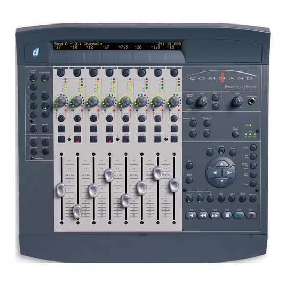
Command|8 Control Surface Figure 1 identifies each of the main Command|8 control sections. LCD Display Meters Control Room Monitor controls Console/Channel View controls Stand-Alone switch USB and MIDI Activity LEDs Modifiers Navigation and Zoom controls Transport controls Fader Strips Figure 1. Command|8 control sections Command|8 Guide... -
Page 25: Lcd Display
Channel View LCD Display Command|8 is in Channel View when any of The LCD is a large, two-row display that shows the Channel View selectors (EQ, Dynamics, In- up to six characters per fader strip. sert or Pan/Send/PRE) is lit in the Channel View area below the LED display. -
Page 26: Fader Strips
To display inserts or plug-in names in the LCD: Channel Faders Make sure the Insert switch is lit in the Con- Each channel has its own 100 mm, servo-driven, sole section. touch-sensitive, motorized fader for controlling levels of audio and MIDI tracks, Auxiliary In- Hold the Display Mode switch. - Page 27 Channel Select Switch Channel Meter LEDs Each channel has a Channel Select switch that Each channel includes a five-segment LED performs several functions, depending on the meter, scaled at 0, –3, –6, –12, and –42 dBFS. view: Global Fader Controls Home View The Channel Select switches select the corresponding track (indicated on-screen by The following controls affect the assignment...
-
Page 28: Console And Channel View Controls For Pan, Sends, And Inserts
Console and Channel View Controls for Pan, Sends, and Inserts The Console and Channel View sections give you control over many on-screen elements in Pro Tools. Plug-in Bypass Display Mode Channel View switches Plug-in Page switches Console View Escape/Cancel switches Insert/Send Position selectors... - Page 29 Insert/Send Position Indicators A–E/F–J Select EQ Identifies channels with equalizer plug-ins the send or insert position to display. These assigned to them by illuminating their Channel switches determine which of the ten available Select switches. If no EQ plug-ins are present, no sends (A–J in Pro Tools) or ten available insert Channel Select switches will be lit.
- Page 30 Pan/Send/PRE Identifies channels with sends Plug-in < Page > Switches Plug-in controls are assigned to them by illuminating their Channel organized in pages. In a process much like bank- Select switches. If no sends are present, no ing of channel faders, when a plug-in has more Channel Select switches will be lit.
-
Page 31: Transport, Navigation, And Zoom Controls
Transport, Navigation, and Zoom Controls These controls mirror the operation of on-screen transport and navigation controls in Pro Tools. In addition, the Function/Utility switches let you invoke special control surface commands. Fader Bank, Nudge, and Display Zoom switches Fader Flip switch Function/Utility switches Master Faders switch Navigation and Zoom keys... - Page 32 Navigation and Zoom Section Function/Utility Switches These multi-purpose switches control the dis- F1 Utility Enters Utility mode. This is where you play of Pro Tools tracks on the Command|8 con- set control surface and input preferences, as well trol surface, on-screen zoom functions, and as run pre-programmed diagnostic tests.
-
Page 33: Control Room Monitor Controls
Headphones Control Room Monitor The Headphone Level adjusts only the output of Controls the Headphone jack (located to the right of the Command|8 provides a Control Room section headphone Level control). for control over monitor and headphone level. To adjust headphone level: Main/External Source switch Adjust the Headphone level control. -
Page 34: Usb And Midi Activity Leds
USB and MIDI Activity LEDs The USB and MIDI Activity LEDs indicate USB and MIDI communication status. USB LED Stays lit when Command|8 is in Pro Tools mode. In other operating modes, the USB LED will flash when controls are moved MIDI LED Indicates MIDI activity at each of the Command|8 MIDI ports. -
Page 35: Chapter 4. Using Command|8 With Pro Tools
chapter 4 Using Command|8 with Pro Tools This chapter explains how to use Command|8 in PLAY Begins playback from the current cursor a Pro Tools session for recording and mixing. position. REC (Record) Arms Pro Tools for recording. Controlling the Transport Record/Playback Mode Switches Use the controls in the Transport section to Use the additional Transport switches to enable... -
Page 36: Navigating
To scroll tracks across the faders one at a time: Navigating Press Nudge. When enabled, its LED is lit. Command|8 lets you select windows, bank Press the Left or Right Arrow keys in the Nav- other tracks to its faders, and zoom in and out igation section to nudge one track to the left, or using the controls in the Navigation/Zoom sec- one track to the right. - Page 37 Zooming To mark a selection by dropping In and Out points: Make sure the Edit cursor is in the track in To zoom in using Command|8: which you want to select material, and begin playback. Press Zoom. When enabled, its switch is lit. At the desired in point, press the Down Arrow Press the appropriate Arrow key in the Naviga- key.
-
Page 38: Recording
Loop Recording, and TrackIn- put monitor switching. Command|8 also di- To create a Memory Location: rectly supports the Digidesign PRE remote con- Cue Pro Tools to the desired location, or begin trollable microphone preamp. playback. -
Page 39: Quickpunch Recording
To take tracks out of record enable: QuickPunch Recording Press the Rec switch. When the Record Enable Command|8 supports QuickPunch recording. function is active, the Record Enable switch For more information on QuickPunch, see the flashes. Pro Tools Reference Guide. Press the Channel Select switch on any track To record using QuickPunch: whose Record Ready indicator is flashing to dis-... - Page 40 TrackPunch and Record Enabling Tracks To take tracks out of TrackPunch and record enable: Before tracks can be punched in and out using Press Ctl/Clutch+Select (Windows) or TrackPunch, they must first be TrackPunch en- /Ctl+Select (Mac) on each track. One press im- abled as well as record enabled.
-
Page 41: Loop Recording
To punch multiple tracks simultaneously using TrackInput Monitor Switching TrackPunch: (Pro Tools|HD Systems Only) Enable TrackPunch mode. To use TrackInput monitoring: Press the Rec switch, then press the channel Select switch to TrackPunch enable and record Press Opt/Alt All+Mon/ø (Windows) or enable tracks. - Page 42 PREs can be in use, unit and channel number are indicated as follows. Controlling PRE PRE unit number (top row) per channel (lower row) as (Digidesign PRE Microphone Pre-Amp) displayed in the LCD If you use one or more PRE units with your 1/1 xx...
-
Page 43: Sends
To display sends on a single track (Channel View): Sends Press the Pan/Send switch in the Channel View switch section. Command|8 lets you adjust Pro Tools send level, pan, pre/post fader tap, and send mute. Press a channel Select switch. (You cannot assign or remove sends from Com- Do one of the following: mand|8;... -
Page 44: Plug-Ins And Inserts
Muting Sends For stereo tracks with stereo sends, pressing the Pan/Meter switch immediately to the right of the encoders toggles between left and right sig- To mute a send: nals. Both the LCD and the LEDs above the Press /CTL+Select on the channel contain- Pan/Meter switch indicate whether the left or ing the send you want to mute. - Page 45 Target Plug-ins and Plug-in Windows Press the channel Select switch that corre- sponds to the name of the plug-in you want to Command|8 can select, target, and open the view. Command|8 displays the first page of window of a plug-in. Whenever you open a plug-in parameters across the LCD.
- Page 46 Closing Plug-in Windows Bypassing Plug-ins Command|8 provides the following ways to by- To close all plug-in windows: pass inserts. Press OPT/ALT ALL+Plug-in (in the Windows section). To bypass the currently focussed insert: Select an insert for editing and display its con- Adjusting Plug-ins trols in the LCD.
- Page 47 Multi-Mono Plug-ins To access an EQ or Dynamics plug-in: Press the EQ or Dynamics switch in the Chan- When working with a multi-mono plug-in, you nel View section. Any currently banked tracks can toggle the view between the left and right containing EQ or Dynamics plug-ins are indi- sides.
-
Page 48: Creating Custom Plug-In Maps
To take a plug-in out of Learn mode, do one of the Creating Custom Plug-In Maps following: Click the active Learn button in the plug-in You can customize the arrangement of plug-in window. parameters on Command|8 and save them in customized plug-in maps. -
Page 49: Automation Functions
To change parameter mapping in a plug-in map: Take the plug-in out of Learn mode. Open the plug-in whose custom map you want to change. Automation Functions Choose the map you want to change from the plug-in window Map Preset pop-up menu. (Pro Tools|HD Systems Only) Put the plug-in into Learn mode. -
Page 50: Software Synths And Rewire Applications
Software Synths and Rewire Applications Command|8 automatically supports any soft- ware synthesizers running as TDM or RTAS plug- ins in Pro Tools (see “Plug-ins and Inserts” on page 38). Stand-alone software synths, samplers, effects, and Rewire-compatible applications (such as Reason, Live, and similar) can also be controlled by Command|8, letting you switch back and forth between environments while maintaining tactile control of session functions. -
Page 51: Chapter 5. Using Stand-Alone Mode
chapter 5 Using Stand-Alone Mode This chapter explains how to configure and op- applications support USB MIDI communication erate Command|8 in Stand-Alone mode. and the Command|8 Personality protocol, or if 5-pin DIN MIDI connections are required to a compatible MIDI interface. Overview of Stand-Alone MIDI Compatibility Mode... -
Page 52: Selecting Stand-Alone Mode
Programming Command|8 faders, encoders, Move any fader to see its position displayed in and switches for the device you are controlling, the lower row of the LCD. if necessary, with custom naming options (see Editing a preset does not automatically save “Editing MIDI Maps”... -
Page 53: Mapping
To select the currently displayed preset, select Mapping Recall by pressing the channel 7 Select switch. The LCD prompts you to confirm that you want Command|8 faders, encoders, and 24 of its to recall and load the selected preset from inter- switches can be programmed, or mapped, to CC nal flash memory. -
Page 54: Editing Midi Maps
Switches In Stand-Alone mode, 32 of the Com- Transport Switches The Transport switches are mand|8 switches are available in both pages of permanently mapped to standard MMC (MIDI each preset. Machine Control) messages. (The RTZ switch does not support MMC.) The following controls are not programmable: Programmable switch rows... - Page 55 Press F2/MIDI Edit. The F2 switch LED flashes, Press F2/MIDI Edit to exit MIDI Edit mode. If and the LCD display shows parameters similar you have changed any settings, you will be to the following tables (which show default as- prompted to save before exiting.
- Page 56 To set the CC#: Programming Faders Rotate the channel 4 encoder for CC# until Each fader can be mapped to any MIDI continu- the desired value is displayed. ous controller. Each fader defaults to a unique MIDI CC number corresponding to Volume To set a Lo or Hi MIDI Value: (#07).
-
Page 57: Presets To Save And Recall Maps
Saving Command|8 Presets Presets to Save and Recall Command|8 presets can be saved to flash mem- Maps ory to save custom mapping of programmable Presets are snapshots of MIDI mapping assign- controls, custom names, and all other parame- ments that can be saved and recalled. ters associated with all eight presets. - Page 58 Loading and Saving Presets with When Command|8 prompts you to save the currently displayed preset to flash memory, do SysEx one of the following: Command|8 supports SysEx to store and recall • To confirm and save, press the channel 7 presets into and out of Pro Tools or any compat- Select switch (Okay).
- Page 59 Naming Presets Naming Controller Assignments You can save custom names for presets, making You can give each programmable control its it easier to manage multiple presets for different own custom name. Some people get by with the devices. default controls and their own memory. Others will appreciate the ability to give parameters names that indicate the control to which they To name a Command|8 preset:...
- Page 60 Command|8 Guide...
-
Page 61: Appendix A. Utility Functions
appendix a Utility Functions Command|8 Utility functions include the fol- Viewing Command|8 Version lowing: Data • Viewing software and firmware versions • Calibrating faders This Utility function lets you check the current • Testing of faders, encoders, LEDs, switches, firmware version and other statistics useful and the LCD when upgrading, or when contacting technical support. -
Page 62: Fader Utilities
Fader Test Fader Utilities Use this test to troubleshoot the mechanical el- ements of the Command|8 faders. Fader Calibration Use this routine to return the motorized, touch- To test fader resolution: sensitive faders to their factory calibration set- Press F1 Utility, if necessary, to enter Utility ting. -
Page 63: Led Tests
LED Tests LCD Display Test Use this test to check all LEDs of similar color si- Use this test to assess the performance of the multaneously. LCD display. To test LEDs: To test the LCD display: Press the F1 Utility switch to enter Utility Press the F1 Utility switch to enter Utility mode. -
Page 64: Switch Test
Switch Test Burn-In Test Use this test to evaluate the performance of Use this test to activate all of the indicators and Command|8 switches. controls on Command|8 simultaneously. To test switches: To run the Burn-In Test: Press the F1 Utility switch to enter Utility Press the F1 Utility switch to enter Utility mode. -
Page 65: Index
index Symbols @ (inactive send or insert) 37 dBFS 21 AC power 9 Edit switch (window display) 30 Arrow keys Ext Source 11 defining selections 31 moving selections up and down 31 audio connections 6, 10 F1 Utility 55 Audio MIDI Setup (AMS) (Mac) 12, 13 F2 MIDI Edit 49 AutoMatch function 43 F3 PRE/MIDI Recall 36... - Page 66 modes Flip mode 21 In and Out points 31 Learn mode 42 inactive operational 17 display of plug-in status 39 Monitor Inputs 11 display of send status 37 monitoring inserts 38, 39 Auto Input and Input Only 35 Instrument tracks 30 connections 10 using TrackInput 35 moving selections 31...
- Page 67 Reason (Propellerhead) 45 testing faders 56 recording LCDs 57 Loop mode 35 LEDs 57 MIDI 36 rotary encoders 58 monitor modes 35 switches 58 QuickPunch mode 33 TrackPunch mode 33, 34 TrackInput monitoring 35 ReWire 45 TrackPunch 34 see Stand-Alone mode TrackPunch mode 33, 34 tracks metering 21...
- Page 68 DIGIDESIGN TECHNICAL SUPPORT (USA) PRODUCT INFORMATION (USA) INTERNATIONAL OFFICES Visit the Digidesign website 2001 Junipero Serra Boulevard Tel: 650.731.6100 Tel: 800.333.2137 for contact information Daly City, CA 94014-3886 USA Fax: 650.731.6375 Tel: 650.731.6300 Fax: 650.731.6399...
Need help?
Do you have a question about the Command 8 and is the answer not in the manual?
Questions and answers