Table of Contents
Advertisement
Quick Links
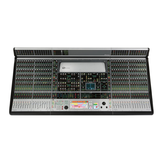
D-Control Desk Module
Installation Guide
2001 Junipero Serra Boulevard
Daly City, CA 94014-3886 USA
Visit the Digidesign Web site
Digidesign
tel: 650·731·6300
fax: 650·731·6399
Technical Support (USA)
tel: 650·731·6100
fax: 650·731·6384
Product Information (USA)
tel: 650·731·6102
tel: 800·333·2137
International Offices
for contact information
Web Site
www.digidesign.com
Advertisement
Table of Contents

Subscribe to Our Youtube Channel
Related Manuals for DigiDesign D-Control


Summary of Contents for DigiDesign D-Control
- Page 1 2001 Junipero Serra Boulevard Daly City, CA 94014-3886 USA tel: 650·731·6300 fax: 650·731·6399 Technical Support (USA) tel: 650·731·6100 fax: 650·731·6384 Product Information (USA) tel: 650·731·6102 tel: 800·333·2137 International Offices Visit the Digidesign Web site for contact information Web Site www.digidesign.com...
- Page 2 Copyright This guide is copyrighted ©2004 by Digidesign, a division of Avid Technology, Inc. (hereafter “Digidesign”), with all rights reserved. Under copyright laws, this guide may not be duplicated in whole or in part without the written consent of Digidesign.
-
Page 3: Table Of Contents
D-Control Desk Module Features........ - Page 4 Desk Module Installation Guide...
-
Page 5: Chapter 1. Introduction And Overview
Digide- sign ICON system. Its distinctive industrial design maintains Any number of Desk Modules can be added to a D-Control the professional look and adds a new dimension of conve- system, up to the maximum possible D-Control stand size, nience to the D-Control console. -
Page 6: Desk Module Top Panel
Rack Spaces Desk Module to protect and hide from view any rack-mounted The 19-inch rack section on the D-Control Desk Module com- gear and cabling under the console. prises a total of 11U rack spaces, and can accommodate the following: •... -
Page 7: Chapter 2. Installing A Desk Module
If you are adding a Desk Module to a previously installed sys- 16-Fader System Plus Desk Module tem, you will first need to rebuild the D-Control stand to ac- If you are building a 16-fader D-Control and a Desk Module, commodate the larger configuration. - Page 8 To move the spacer plate: Remove the screws holding the spacer plate in place. Make If you are building a D-Control system with more than 16 fad- sure to note the location of the longer screws (2 in the front ers and a single Desk Module, you can place the Desk Module and 5 in the back) as you remove them.
-
Page 9: Installing The Units On The Stand
Leveling the Pins on the Rightmost Unit Installing the Units on the Stand Each D-Control unit ships with two pins in its right side to an- After the D-Control Main Unit, Fader Modules, and Desk chor the units together on the stand. These pins are not Modules are prepared for installation, the units are placed on needed on the rightmost unit in your configuration. -
Page 10: Installing The Rack Equipment Enclosure
For details on closing up the stand and installing the Lift the Back panel into place on the back of the Desk Mod- plastic side and leg caps, refer to the D-Control ule and attach it to the bottom of the module with M4 x 8 mm Guide or the D-Control Expanded System Guide. - Page 11 Lift a side panel into place under the Desk Module and align Attach the front panel to the Desk Module with M4 x 8 mm it with the back panel. (You will need to tilt the panel at an an- Philips pan head screws.
- Page 12 Tighten all of the screws that attach the enclosure to the Desk Module. When the enclosure is assembled, you are ready to mount equipment in the rack area of the Desk Module. Figure 19. Assembled rack equipment enclosure Mounting Equipment in the Desk Module Equipment Depth When mounting equipment in the Desk Module, check to...
Need help?
Do you have a question about the D-Control and is the answer not in the manual?
Questions and answers