Table of Contents
Advertisement
+++ DIGITAL
+++
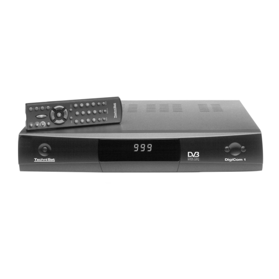
DigiCom 1
for the reception of free-to-air DVB channels
Operating Instructions
This receiver enables you to receive
the free-to-air digital ASTRA and
EUTELSAT channels free of charge.
+++ DIGITAL
+++
DIGITAL+++ DIGITAL
DIGITAL+++ DIGITAL
+++
DIGITAL+++ DIGITAL
+++
DIGITAL+++ DIGITAL
+++
+++
Advertisement
Table of Contents

Subscribe to Our Youtube Channel
Related Manuals for TechniSat DigiCom 1


Summary of Contents for TechniSat DigiCom 1
-
Page 1: Operating Instructions
+++ DIGITAL DIGITAL+++ DIGITAL DIGITAL+++ DIGITAL DigiCom 1 for the reception of free-to-air DVB channels Operating Instructions This receiver enables you to receive the free-to-air digital ASTRA and EUTELSAT channels free of charge. +++ DIGITAL DIGITAL+++ DIGITAL DIGITAL+++ DIGITAL... - Page 2 4-digit LED display Channel Power up/down Scart socket Scart socket LNB input V O R S I C H T ! E L E K T R O S C H O C K - G E F A H R N I C H T Ö...
-
Page 3: Remote Control
Remote Control Remote Control Option: Use these buttons to set SAT1 resp. SAT2 enabling the opera- tion of your DVB POWER Transponder information Programme information INFORMATION Channel VOLUME -/+ (up/down) Cursor (left/right) Cursor (up/down) BACK Number keys Language A/B MONO1/MONO2 EXTERN MUTE MENU... -
Page 4: Table Of Contents
Contents Contents Illustrations Safety precautions – Please read first! Connection Mains connection Outdoor unit 4.2.1 Single reception 4.2.2 Operation with an additional receiver Connection to a TV set Adjusting the UHF output channel Video Cassette Recorder (VCR) 4.5.1 Super VHS VCR AUX IN/OUT Amplifier Serial/parallel port... - Page 5 Using the operating instructions ½ Before connecting the receiver, please read the safety precautions in chapter 3 first. ½ The chapters 4 and 5 describe the initial installation, how to connect and adapt the receiver to the outdoor unit (antenna, LNB,...), to the TV, VCR, etc.. This set- up is required at initial installation and only needs to be supplemented if the outdoor unit changes or additional equipment are connected.
-
Page 6: Safety Precautions
Safety precautions For your own protection, carefully read the safety precautions before starting to use your new device. The manufacturer is not liable for damage caused by improper handling or by disregarding the safety precautions. ½ Never place any objects on top of the device. The openings need to be uncovered for heat to escape from the inside. -
Page 7: Connection
Connecting the DVB receiver with a satellite system Connecting the LNB with the LNB input of the DVB receiver. Connecting the LNB output of the DVB receiver with the LNB input of the analogue receiver Mains connection Connecting the terrestrial antenna with the antenna input ARIAL of the DVB receiver Connection of an analogue device with the Scart socket AUX IN/OUT of the DVB receiver. -
Page 8: Mains Connection
Connection The letters a b c ... found in the following paragraphs refer to the drawing on page 5. Mains connection The receiver should only be connected to the mains after the cabling with all components is completed. This eliminates damage to the receiver or other components. -
Page 9: Adjusting The Uhf Output Channel
Adjusting the UHF output channel Proceed as follows: ½ Call Main Menu with the MENU button. Main menu TV Programs Radio Programs Search Timer Settings OSD Language ½ Choose the menu line Settings by marking the corresponding line red with the help of the cursor keys up/down. -
Page 10: Video Cassette Recorder (Vcr)
½ Set your TV set to a free UHF channel between 21 and 61. ½ Enter the new output channel number with the number keys of your remote control. The new UHF channel is now indicated on the receiver display. If you still do not receive a clear picture, please repeat this procedure until you have found a suitable channel. -
Page 11: Serial/Parallel Port
Serial/parallel port 4.8.1 Serial port RS 232 The SERIAL PORT RS 232 is used for updating the operation software and pre- programming via PC. 4.8.2 Parallel port IEEE 1284 The PARALLEL PORT is used for data exchange via a PC with a special software. Since there is no application for this at present the existing software does not support this function. -
Page 12: Basic Settings
In order to be able to optimally use your DVB receiver, you need to adjust it to your individual needs. ½ Call Main Menu with the MENU button. ½ Choose the menu line Settings by marking the corresponding line red with the help of the cursor keys. - Page 13 Explanation for the OSD menu: Main >Basic Menu>Settings ___________________________________________________________________ Parental Control: The receiver is equipped with a child lock. Channels that have been locked according to 6.3 and 6.4 can only be tuned in after a 4-digit PIN has been entered.
-
Page 14: Installation
Installation After you have adjusted your receiver to your individual needs you may have to adjust it to your antenna, if necessary. The receiver was factory pre-programmed to ASTRA and EUTELSAT with a Universal-LNB (see appendix: Technical terms). These channels will be received after installation of the receiver without additional adjustments. - Page 15 ½ Select the desired satellite with help of the cursor keys. With the buttons cursor up/down the marker moves a line up or down, the cursor keys left/right turn to the previous or next page. If the desired satellite does not appear on the list, please select one of the spare positions, marked with User 1 to 17 (e.g.
-
Page 16: Channel Search
Transponder test You only need to enter the following points, if you want to test a satellite signal of a satellite you entered yourself (User 1 to 17). Transponder frequency Please, enter the frequency for the transmission of digital broadcasts with the help of the number keys. - Page 17 ½ Call the main menu with the MENU button. Main menu TV Programs Radio Programs Search Timer Settings OSD Language ½ Now choose the menu line Search by marking it red using the cursor keys up/down. ½ Confirm with OK. The sub-menu Search appears.
- Page 18 This menu enables you to start a specific channel search for one transponder (see 9 Technical terms). This, however, requires that the transponder data is entered. ½ Choose the menu line Transponder and mark it red by using the cursor keys up/down.
-
Page 19: Reset To Factory Settings
Reset to factory setting 5.5.1 Complete deleting of all channel memories You can return to the factory LNB setting anytime. You can also delete this completely and start a new channel search in case the channel list is out-of-date due to broadcaster changes. -
Page 20: System Configuration
½ Select the desired function with help of the cursor keys. ½ Confirm with OK. Keep an eye on appearing messages on the screen. System configuration In this menu you will find the specific data of the receiver. ½ Call Main Menu with the MENU button. ½... -
Page 21: Sorting Of Channels
½ Choose the menu line Select by marking the corresponding line red with the help of the cursor keys up/down. ½ Confirm with OK. The sub-menu Select appears. Here you will find a list of the bouquets with their channels. Existing channels are printed in black and newly found channels are printed in red. -
Page 22: Locking Of Channels
Locking of channels You have the possibility to lock channels. If a locked channel is tuned in, you will see a black screen with the message "Program not available". A locked channel will be shown on the screen only after you have entered you PIN number. -
Page 23: Cancelling The Locking Of Individual Channels
Cancelling the locking of individual channels After you have entered your PIN to open the menu proceed like mentioned under 6.3 and remove the red crosses with the OK button. This enables you to remove the child lock from individual channels. Operation Switching on/off ½... -
Page 24: Information Box
If you try to tune in to a channel that is locked with Parental control you will see the message PIN number on the screen. ½ Now enter your PIN number with the use of the number keys of your remote control. -
Page 25: Returning To The Previous Channel
Returning to the previous channel ½ The button BACK on your remote control will switch to the station tuned in previously. ½ On pressing the button again you will be returned to the station watched/listened to before. Display of time and programme information This function will display the time and information about the tuned in programme. - Page 26 Explanation for the OSD menu: Main Menu>Timer ___________________________________________________________________ Source Enter TV or Radio with help of the button OK, to record a TV or radio programme. Program Number/Name ½ Press OK. A channel list will appear. (In TV mode TV channels and in radio mode radio channels.) ½...
-
Page 27: Troubleshooting Notes
Troubleshooting notes Problem Possible cause What to do No picture, no sound, No power supply Check main power supply display is dark No picture, no sound, Short circuit in LNB cable Turn unit off, remove short display is on circuit, turn unit on again Defect or missing cable Check all cable connections... -
Page 28: Technical Terms
Technical terms Antenna cable Connection between modulator of receiver and antenna input of TV (alternative: if no scart cable is available). Outdoor unit Contains the complete outdoor system, including a parabolic/offset dish and one or several LNBs for the reception of one or several satellites. AV (see SCART) Data compression/MPEG1/MPEG2 The quantity of digital data for the transmission of today’s TV standard (625 lines and... - Page 29 LNB/LNC (Low Noise Block Converter) Reception unit in the focal point of the parabolic antenna, converts the satellite frequency into the intermediate frequency of the receiver. Local Oscillator Frequency: measured in MHz or GHz, depending on LNB and received frequency range. Reception frequency range of the receive = transmission frequency of the satellite - Modulation with 22 kHz Serves as a 14/28 Volts switch and as a switch between 2 LNBs.
-
Page 30: Technical Data
Processes one or more channels on a satellite. That is: reception of the data of the ground station, amplification and transmitting back to earth. Universal-LNB A three band LNB for the reception of the frequency ranges FFS (10.70 - 11.70 GHz), BBS (11.70 - 12.50 GHz) and FFS high band (12.50 - 12.75 GHz). - Page 31 Conversion 16:9 Automatic adjustment for 16:9 TV sets (via SCART) Letterbox filtering for 4:3 TV sets Audio decoding: Audio compression MPEG1 & MPEG2 Layer I and II Audio mode Dual (main/sub), stereo Sampling frequencies 32 kHz, 44.1 kHz, 48 kHz, and 16 kHz, 22.05 kHz, 24 kHz Parameter: Audio output parameter, analogue:...
- Page 32 Input impedance 75 Ohms Output level 70 dBµV ± 3 dB Output impedance 75 Ohm LNB power supply: LNB current 400 mA max.; short circuit protected LNB voltage vertical < 14.0 V without load, > 11.5 V at 400 mA load LNB voltage horizontal <...
- Page 33 Your DVB receiver is licensed and fulfills all necessary EU requirements! Changes and printing errors excepted. Issue 01/99 TechniSat is a registered trademark of TechniSat Satellitenfernsehprodukte GmbH Postfach 560 – D-54550 Daun - Germany ---------------------------------------------------------------------------------------...
- Page 34 The daily application Switching on/off ½ Turn the receiver on by pressing the button POWER at the device or on your remote control. ½ On pressing the POWER button again, the receiver will be turned off. ½ Now, the receiver is in standby mode and the time will be indicated in the display of the receiver.
Need help?
Do you have a question about the DigiCom 1 and is the answer not in the manual?
Questions and answers