Table of Contents
Advertisement
Quick Links
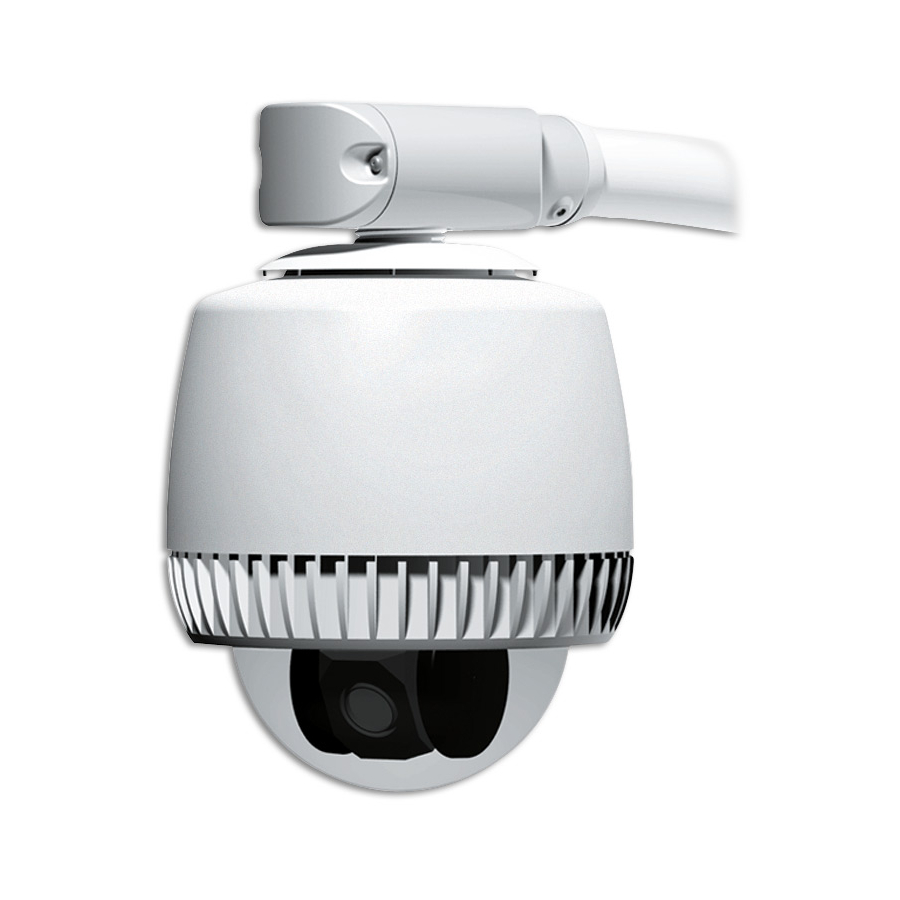
ADSDUHOC, ADSDUHOS, ADSDUHOVRC, ADSDUHOVRS
SpeedDome
At end of pipe.
Ensure black foam plug is around
cable and press-fit into pipe.
See A, B, C.
Line up.
1
Thread cables through end
cap assembly and attach
housing to mounting
structure.
B
Keep cables from
twisting while turning
housing.
®
Ultra Outdoor Housing Installation Guide
= Step Prevents
Before performing these steps, read additional
Water Intrusion.
information attached for important details and
warnings!
2
Sleeve
Seal
Ensure seal and sleeve are
properly set.
Green 3-Pin Connector (Power)
Pin 1 - Black (24Vac)
Pin 2 - Red (Common)
Pin 3 - White (24Vac)
Green 2-Pin Connector (Twisted Pair Video)
Pin 1 - + (video high)
Pin 2 - – (video ground)
Push to line and
Tighten.
Black Connector (Data)
maintain
compression.
Manchester
Pin 1-4 - Not used
Pin 5 - White/Orange (Manchester W)
Pin 6 - White/Yellow (Manchester B)
RS-422
Pin 1 – Orange (Rx +)
Pin 2 – Green (Rx –)
Pin 3 – Yellow (Tx +)
Pin 4 – Brown (Tx –)
Pins 5-6 - Not used
SensorNet
Pin 1-4 - Not used
A
Pin 5 - White/Orange (SensorNet Hi)
Pin 6 - White/Yellow (SensorNet Lo)
Turn until no threads
are exposed.
Attach cable
connectors.
Gray 5-Pin Connector
(Relay)
Pin 1 - Blue (NC)*
Pin 2 - Purple (Common)*
Pin 3 - Gray (NO)*
Pin 4 - White/Red (Alarm Return)
Pin 5 - White/Black (Alarm 1)
* Relay contact not to exceed 1A @
30Vdc or 0.3A @ 125Vac.
Blue 4-Pin Connector
(Alarm)
Pin 1 - White/Blue (Alarm 2)
Pin 2 - White/Brown (Alarm 3)
Pin 3 - White/Purple (Alarm 4)
Pin 4 - White/Red (Alarm Return)
IMPORTANT!
This housing meets IP66/Nema 4 ratings
provided it is used with a properly installed ROENDC End
Cap Assembly and one of the following mounts: RHOTR
Over-the-Roof Mount, RHOSW Short Wall Mount, or
RHOLW Long Wall Mount.
3
Make connections,
insert cables into end
cap assembly, and
attach cover.
A
B
C
Check o-ring is
properly set.
Page 1 of 12
8200-0492-02, Rev. C
-
Advertisement
Table of Contents

Related Manuals for American Dynamics SpeedDome Ultra Outdoor Housing ADSDUHOC


Summary of Contents for American Dynamics SpeedDome Ultra Outdoor Housing ADSDUHOC
- Page 1 ADSDUHOC, ADSDUHOS, ADSDUHOVRC, ADSDUHOVRS ® SpeedDome = Step Prevents Water Intrusion. At end of pipe. Seal Ensure black foam plug is around Ensure seal and sleeve are cable and press-fit into pipe. properly set. See A, B, C. Line up. Push to line and maintain compression.
- Page 2 x100 Set the dome address. The address range is from 001 to 255, except for Manchester, which is 01 to 64. Set switches. Example: For address 107, set SW3 to 1, SW2 to 0, and SW1 to 7. Remove and discard both eyeball covers.
-
Page 3: Table Of Contents
SpeedDome Ultra ® Outdoor Housing Installation Guide–Continuation ADSDUHOC ADSDUHOS ADSDUHOVRC ADSDUHOVRS Contents: To the Installer... 3 About the Product... 3 Parts Supplied ... 3 Tools Required ... 3 Warnings and Cautions ... 4 Preventing Condensation ... 5 Parts List for Authorized Users ... 5 Connector Pin Assignments ... -
Page 4: Warnings And Cautions
Amps, meeting section 2.11 of IEC950, and a maximum of 250VA available. The power supply can be obtained through American Dynamics or through another source where the provider can furnish the required certification. This is required to assure electrical safety in the product. -
Page 5: Preventing Condensation
Preventing Condensation Damage, missing parts, or procedures that most often allow water to enter the housing are as follows (refer to figures opposite): Missing O-ring on cover, or missing sleeve or seal on end cap assembly Missing Teflon tape around any housing pipe threads RTV or similar sealant covering an air path Blower fans not turning... -
Page 6: Power Cable
Connector Pin Assignments GREEN CONNECTOR (POWER) Color Description Black 24Vac Common White 24Vac BLACK CONNECTOR (DATA) Manchester Color* Designation — Not used. White/Orange Manchester (White) White/Yellow Manchester (Black) RS-422 / SensorNet Color* Designation Orange RS-422 Data In High (+) Green RS-422 Data In Low (–) Yellow RS-422 Data Out High (+) -
Page 7: Housing Termination And Video Configuration
Housing Termination and Video Configuration Both the outdoor housing and dome camera are shipped “terminated” for when they are installed at the end of a data cable. Should the cable continue to another dome, “unterminate” the housing using the following procedure. IMPORTANT! Leave the dome camera set to “terminated.”... - Page 8 4. On the circuit board is a mark (shown below). To reattach the board to the housing, match the mark to an identical mark on the base and snap the board in place. 5. Gently remove the dust cover. Note: Keep the cover and use it to protect contacts should the environmental PC board need to be removed from the housing.
-
Page 9: Troubleshooting
Troubleshooting This section covers what to do when: • Dome does not respond to commands • Fans do not turn • Picture is grainy or discolored • Poor video • Ice forms on bubble. CAUTION: Some steps in this section involve tightening wire connections. - Page 10 SensorNet Data Connections Color Designation — Not used. White/Orange SensorNet (unshielded) White/Yellow SensorNet (unshielded) 4. Check fans. Are they on? - YES: Continue. - NO: Go to “Fans Do Not Turn” procedure next. 5. Check video on monitor. Does the picture roll? - YES: Use the video controller or switcher to synchronize video vertical sync phases of all domes to the ac line.
-
Page 11: Specifications
Ice Forms On Bubble Follow steps until the problem is corrected. See page 5 to order parts. 1. Are blower/heater fans in the housing working? If not, see “Fans Do Not Turn” opposite. 2. Is the camera dome receiving power? Look for evidence such as a picture on the video monitor or dome movement. -
Page 12: Regulatory Compliance
SPEEDDOME ULTRA OUTDOOR HOUSING INSTALLATION GUIDE - CONTINUATION Other Declarations Thank you for using American Dynamics products. We support our products through an extensive and worldwide network of dealers. The dealer, through whom you originally purchased this product, is your point of contact if you have a need for service or support.
Need help?
Do you have a question about the SpeedDome Ultra Outdoor Housing ADSDUHOC and is the answer not in the manual?
Questions and answers