Advertisement
Quick Links
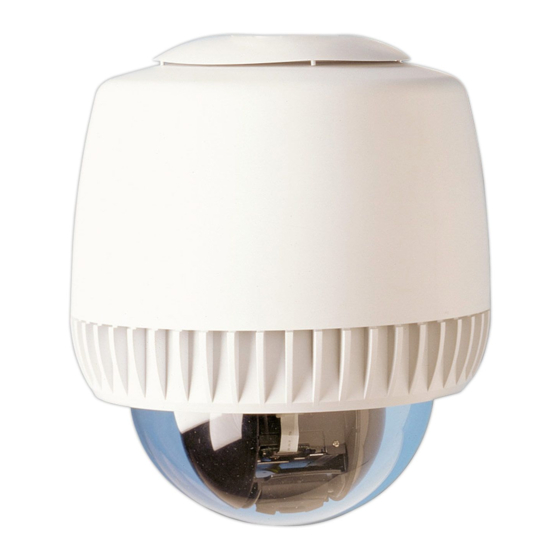
This guide explains how to install the VideoEdge IP SpeedDome
using the VideoEdge SpeedDome Outdoor Housing with an
ROENDC or a RHOPN mount.
For information on installing these mounting kits see the relevant
instructions provided in the packaging.
●
RHOSW/RHOLW Installation Guide.
8000-2692-08
●
RHOPN Installation Guide.
8000-2692-12
●
RHOTR Installation Guide.
8000-2692-06
●
ROENDC Installation Guide.
8000-2692-04
Warnings
Please review the following warnings before you install or service
the camera dome.
ALWAYS USE:
●
Proper safety equipment for the location and type of installation.
●
Proper lift equipment to reach the installation.
●
Safety features of the lift equipment.
BE SURE:
●
Electrical power is not connected to the camera when connecting wires
since the camera will move when power is applied.
●
Electrical power is not connected to nearby fi xtures that you might touch
during installation.
●
DO
NOT install this dome in hazardous areas where highly combustible or
explosive products are stored or used.
1
What's in the box
●
Pendant Housing
●
3 way power connector (Green)
2109-0651-03
●
4 way alarm connector (Blue)
2109-0804-04
●
5 way alarm connector (Gray)
2109-0650-05
●
Cable tie
6009-0056-01
●
Silica bag kit
0352-0207-02
Tools Required
●
Screwdriver
● Allen Wrench
●
Pliers
● Power Drill
●
Socket wrench kit with extension (metric) Screwdriver
Before You Begin
To ensure a smooth and successful installation, observe the
following requirements.
General Requirements
●
Have electrical work comply with latest national electrical code, national
fi re code, and all applicable local codes and ordinances.
●
Coordinate work with other trades to avoid interference.
●
Verify existing site conditions and coordinate with the owner's
representative and appropriate utilities as required.
●
Obtain copies of all related plans, specifi cations, shop drawings and
addenda to schedule and coordinate related work.
●
Thoroughly review the project to ensure that all work meets or exceeds
the above requirements. Bring alleged discrepancies to the attention of
the CCTV Project Coordinator.
Preparing the VideoEdge IP Dome Camera
3
1.
Remove the VideoEdge IP SpeedDome camera from the
housing.
2.
Gently swivel eyeball to totally expose one of the two slot covers.
Caution: Swivelling the eyeball fast may damage gears.
3.
Insert small, thin-bladed screwdriver into the space between
cover and eyeball.
4.
Gently pry off slot cover.
5.
Gently swivel the eyeball to totally expose remaining slot cover.
With the other cover removed this cover can be easily removed.
The SD MicroCard is an optional accessory. It is required for
audio clips and to enable emailing or FTP of video fi les. The
maximium size of SD MicroCard that can be used is 2GB.
Caution: Disconnect the power before installing or replacing the SD
MicroCard.
6.
Insert the SD MicroCard into the slot as shown if required.
4
Removing the metal adaptor plate
Unscrew the 3 retaining screws on the metal adaptor plate
1.
Turn the metal adaptor plate anti-clockwise to release it from the
2.
housing
Slide the adaptor plate down and out of the housing
3.
Note: The plate is attached by a safety lanyard to the housing. You are not
required to remove this safety lanyard.
You may now attach the prepared VideoEdge IP dome camera to
the metal adaptor plate.
VideoEdge SpeedDome Outdoor Housing Installation Guide
ADVESDHOC, ADVESDHOS, ADVESDHOVRC, ADVESDHOVRS
Preparing an Outdoor Housing with a ROENDC
2a
If a junction box or patch panel is being used then:
Prepare cabling of suffi cient length to ensure connection of the
1.
camera to the junction box and to enable easy servicing.
If a junction box or patch panel is not being used then, ensure
that the appropriate cables are in place for the installation.
Remove pipe elbows (if any), and then make a mark 4 cm ( 1.6 in)
2.
from the end of the existing pipe.
Slip the cable into the hole of the dust plug and work the plug into
3.
the pipe opening.
Note: The plug must be fully inserted and must fully seal the opening
Thread the two set screws provided into the adapter pipe. Also, to
4.
prevent water intrusion, ensure the adapter pipe has gasket and
rubber seal pre-installed.
Gasket (seat in groove at bottom of opening)
Set screw (2)
5.
Run the cables from the existing pipe through the end cap and out
its front end.
6.
Install the end cap as follows:
Note: If the marks on the pipe of the mounting structure are missing, scribe a
circumference mark 4cm (1.6in) from the end of the pipe. See step 2.
a) Align the arrow on the adaptor pipe with the mark at the top of
the pipe assembly.
b) Maintaining arrow/line alignment, insert the end cap assembly
over the pipe until the rubber sleeve on the adapter meets the
circumference mark.
Note: To ensure a good seal on the mounting it is recommended that you
tighten the two set screws sequentially and evenly and do not over tighten
them.
c) Tighten the two set screws using the allen wrench.
7.
Check the level of the pipe assembly. If re-leveling is necessary,
loosen the two set screws and repeat step 6 a - c.
8.
Remove the housing from the packaging.
9.
Cut a 30cm (12 in) length of tefl on tape.
Attaching the Videoedge IP Dome Camera to the
5
Metal adaptor plate
1. The metal adaptor plate has 2 circular
cut outs to allow the camera dome
standoff guides to pass through it.
Using the 2 standoff guide pins in the
camera dome as a reference attach
camera dome to the metal adaptor
plate.
2. Secure the metal adaptor plate to the
camera by sequentially tightening the
three locking screws.
Note: The silica bag is attached to the metal
adapter plate with a cable tie and positioned
next to the dome. (It needs to be replaced
whenever the housing is reopened to absorb
initial humidity inside the housing).
6
Attaching the assembled Camera Unit
1.
Hang the assembled camera unit on the housing dome holder, the
yellow guide arrows indicate which slot to hang the unit from.
Warning: When connecting wires, ensure that electrical power is not
connected to the camera dome. The dome will move when power is applied.
Also, ensure electrical power is not connected to nearby fi xtures you may
come into contact with during the installation.
2. For ease of installation it is recommended that the cables are
attached in the following order.
●
Green 2 way power cable
●
RJ-45 Ethernet cable
●
White 5 way communication cable
●
White 8 way AV cable
●
Green 8 way Alarm
10.
Apply tefl on tape to the threads at the top of the housing.
11.
Route the cable from the housing through the bottom opening of
the end cap and out its front.
12.
Twisting the cables to avoid tension, screw the housing onto the
adapter pipe.
13.
Keep turning the housing until tight.
14.
Re-check the level of the pipe assembly and re-level if necessary.
Warning: Perform steps 15-18 only if there is no power connected. If power
is present, defer these steps until ready to install the bubble.
15.
Plug the power and data connectors from the incoming cable to the
corresponding connectors on the pigtail cables on the board.
16.
Route the pigtail cables from the dome through the End Cap.
17.
Place any excess cable into the end cap and ensure the O-ring is in
place.
18.
Using a wrench for tamperproof screws, attach the cover to the End
Cap.
Rubber Seal (seat over opening)
Preparing an Outdoor Housing with RHOPN
2b
1.
Install the RHOPN mount using directions in the RHOPN
Installation Guide (8000-2692-12).
2.
Remove the outdoor housing from the packaging and route the
pigtail cables through the RHOPN mount.
3.
Thread the outdoor housing onto the RHOPN mount while being
careful not to tangle or damage the cables.
Caution: Take care when you are threading the support onto the dome to
avoid any damage to the cables.
4.
Use the two M3 screws provided to fi ll the two empty holes in the
support.
Warning: Only perform step 6 if there is no live power to the End Cap.
5.
Remove 2.5-3.8 cm (1-1.5in) of jacket from the cable end(s) and
install the power and data connectors supplied.
6.
Plug the power and data connectors from the incoming cable to the
corresponding connectors on the pigtail cables.
7.
Lower the cover and secure it to the top of the dome.
3. Remove the assembled unit form the housing dome holder.
4. Rotate the assembled unit approximatley 180° clockwise to align
the cutout on the metal adaptor plate with the corresponding
guide in the housing. (It may help you to align the cutout and
guide if you tilt the assembled camera unit.)
Cutout
5. Slide the assembled camera unit up into the housing until it
touches the fl ange.
6. Maintaining the contact with the
fl ange rotate the assembled unit in a
clockwise direction until the locking
pins engage.
7. Secure the assembled unit into the
housing by sequentually tightening the
three lockingpins.
7
Attaching the Bubble assembly
1.
Remove the bubble assembly from the package and ensure the
bubble is clean and free of debris.
2.
Attach the coiled lanyard from the bubble to the threaded stud on
the indoor housing using the thumb nut supplied.
Guide in the Housing
© 2010 Tyco International Ltd. and its Respective Companies. All Rights Reserved
8200-2613-08 C0
Advertisement

Related Manuals for American Dynamics ADVESDHOC


Summary of Contents for American Dynamics ADVESDHOC
- Page 1 VideoEdge SpeedDome Outdoor Housing Installation Guide ADVESDHOC, ADVESDHOS, ADVESDHOVRC, ADVESDHOVRS This guide explains how to install the VideoEdge IP SpeedDome Apply tefl on tape to the threads at the top of the housing. Preparing an Outdoor Housing with a ROENDC...
- Page 2 VideoEdge SpeedDome Outdoor Housing Installation Guide ADVESDHOC, ADVESDHOS, ADVESDHOVRC, ADVESDHOVRS 3. Attach the bubble assembly. a) Remove the “CAUTION: Remove slot covers” tag. Ensure the Pin-outs for External Housing Connections slot covers are removed. 4. Align the key on the inside of the bubble assembly with the detent 3 wire 24VAC supply (Green) on the edge of the housing.
Need help?
Do you have a question about the ADVESDHOC and is the answer not in the manual?
Questions and answers