Table of Contents
Advertisement
Quick Links
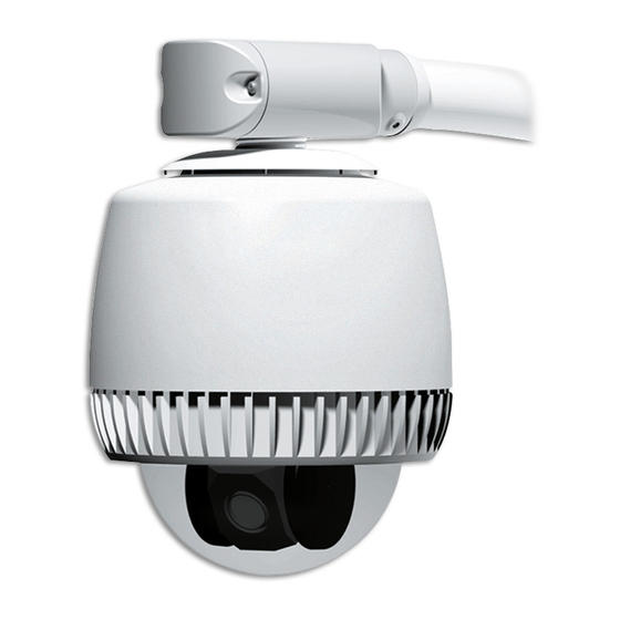
SpeedDome Ultra Outdoor Housing Installation Guide
RHODUL-03E/-03VRE (Clear Bubble), RHODUL-04E/-04VRE (Smoked Bubble)
At end of pipe.
Ensure black foam plug is around
cable and press-fit into pipe.
A
See A, B, C.
Line up.
1
Thread cables through
end cap assembly and
attach housing to
mounting structure.
B
Keep cables from
twisting while turning
housing.
= Step Prevents
Before performing these steps, read additional
Water Intrusion.
information attached for important
details and warnings!
2
Sleeve
Seal
Ensure seal and sleeve are
properly set.
Green Connector (Power)
Pin 1 - 24Vac
Pin 2 - EMI Ground
B
C
Pin 3 - 24Vac
Black Connector (Data)
Manchester
Tighten
Pin 1-4 - Not used
Push to line
Pin 5 - White/Orange
and maintain
Pin 6 - White/Yellow
compresion.
RS-422
Pin 1 - Orange
Pin 2 - Green
Pin 3 - Yellow
Pin 4 - Brown
Pins 5-6 - Not used
SensorNet
Pin 1-4 - Not used
Pin 5 - White/Orange
Pin 6 - White/Yellow
A
*
0100-2468-02 Standard Housing,
Turn until no threads
0101-0061-02 Vandal-Resistant Housing.
are exposed.
Blue alarm connector used with
-02 housings only.*
Attach cable
connectors.
Gray Connector (Relay)
Pin 1 - Blue (Relay NC)
Pin 2 - Purple (Relay armature)
Pin 3 - Gray (Relay NO, 3.5mA sink)
Pin 4 - White/Red (Alarm Return)
Pin 5 - White/Black (Alarm 1, 3.5mA sink)
Blue Connector (Alarm)
(-02 Housing only*)
Pin 1 - White/Blue (Alarm 2, 3.5mA sink)
Pin 2 - White/Brown (
Alarm 3, 3.5mA sink)
Pin 3 - White/Purple (
Alarm 4, 3.5mA sink)
Pin 4 - White/Red (Alarm Return)
IMPORTANT!
This housing meets IP66/Nema 4
ratings provided it is used with a properly installed
ROENDC End Cap Assembly and one of the following
mounts: RHOTR Over-the Roof Mount, RHOSW Short
Wall Mount, or RHOLW Long Wall Mount.
3
Make connections,
insert cables into end
cap assembly, and
attach cover.
A
C
B
Check o-ring is
properly set.
8200-0184-10, Rev. C
Page 1 of 12
Advertisement
Table of Contents

Related Manuals for American Dynamics RHODUL-03E


Summary of Contents for American Dynamics RHODUL-03E
- Page 1 SpeedDome Ultra Outdoor Housing Installation Guide RHODUL-03E/-03VRE (Clear Bubble), RHODUL-04E/-04VRE (Smoked Bubble) = Step Prevents Water Intrusion. At end of pipe. Seal Ensure black foam plug is around Ensure seal and sleeve are properly set. cable and press-fit into pipe.
- Page 2 x100 Set the dome address. The address range is from 001 to 255, except for Manchester, which is 01 to 64. Set switches. Example: For address 107, set SW3 to 1, SW2 to •, and SW1 to 7. Remove and discard both eyeball covers.
-
Page 3: Table Of Contents
SpeedDome Ultra ® Outdoor Housing Installation Guide - Continued RHODUL-03E/-03VRE (Clear Bubble) RHODUL-04E/-04VRE (Smoked Bubble) Contents: To the Installer... 3 About the Product... 3 Parts Supplied ... 3 Tools Required ... 3 Warnings and Cautions ... 4 Preventing Condensation ... 5 Parts List for Authorized Users ... -
Page 4: Warnings And Cautions
Amps, meeting section 2.11 of IEC950, and a maximum of 250VA available. The power supply can be obtained through American Dynamics or through another source where the provider can furnish the verification. This is required to assure electrical safety in the product. -
Page 5: Preventing Condensation
Preventing Condensation Damage, missing parts, or procedures that most often allow water to enter the housing are as follows (refer to figures opposite): Mounts that allow water to enter the air path. If an older horizontal mount is used, replace it with a new model or ensure there is ample slope away from the camera dome and a foam plug is present... -
Page 6: Connector Pin Assignments
BLUE CONNECTOR (ALARM)* Color Designation Alarm input (3.5mA sink) Alarm input (3.5mA sink) Alarm input (3.5mA sink) Alarm Return * -02 housings only. 0100-2468-02 standard housing, 0101-0061-02 vandal-resistant housing. SPEEDDOME ULTRA OUTDOOR HOUSING CONTINUATION OF INSTALLATION GUIDE Cable Requirements Data Cable The table below shows requirements for SensorNet, RS-422, and Manchester networks. -
Page 7: Manual Heater Operation
Manual Heater Operation (-02 Housings Only) The heater in the outdoor dome: - Automatically turns on when temperature inside the housing drops below 18°C (64°F) - Automatically turns off when the temperature inside the housing goes up to 23°C (73°F). -
Page 8: Housing Termination
Housing Termination Both the outdoor housing and dome camera are shipped “terminated” for when they are installed at the end of a data cable. Should the cable continue to another dome, “unterminate” the housing using the procedure opposite. IMPORTANT! Leave the dome camera set to “terminated”. -
Page 9: Troubleshooting
Troubleshooting This section covers what to do when: • Dome does not respond to commands • Fans do not turn • Picture is grainy or discolored • Poor video • Ice forms on bubble. Dome Does Not Respond to Commands Follow steps until the problem is corrected. - Page 10 SensorNet Data Connections Color Designation — Not used. Brown SensorNet (unshielded) Yellow SensorNet (unshielded) CAUTION: Use a 2.5mm (0.1in) slotted screwdriver. Using a blade too wide can damage connectors. CAUTION: Screws on the connector P1 are delicate. DO NOT over tighten them! 4.
-
Page 11: Specifications
Ice Forms on Bubble Follow steps until the problem is corrected. See page 5 to order parts. 1. Are fans in the housing are working? If not, see “Fans Do Not Turn” opposite. 2. Is the camera dome receiving power? Look for evidence such as a picture on the video monitor or dome movement. -
Page 12: Declarations
SPEEDDOME ULTRA OUTDOOR HOUSING CONTINUATION OF INSTALLATION GUIDE Other Declarations Thank you for using American Dynamics products. We support our products through an extensive and worldwide network of dealers. The dealer, through whom you originally purchased this product, is your point of contact if you have a need for service or support.
Need help?
Do you have a question about the RHODUL-03E and is the answer not in the manual?
Questions and answers