Samsung SVR-1680 User Manual
High-resolution real-time digital video recorder
Hide thumbs
Also See for SVR-1680:
- User manual (104 pages) ,
- User manual (89 pages) ,
- Install manual (54 pages)
Table of Contents
Advertisement
Quick Links
Advertisement
Table of Contents

Subscribe to Our Youtube Channel
Related Manuals for Samsung SVR-1680


Summary of Contents for Samsung SVR-1680
- Page 1 User Manual...
-
Page 2: Product Warranty And Limits Of Responsibility
Introduction Thank you for choosing Samsung DVR products. This is the user manual for SVR-3200, SVR-1680, SVR-1660, SVR-1645, SVR-960, SVR-945. Before installing or operating this product, please familiarize yourself with this user manual and other manuals referenced by this manual. - Page 3 All installation operations should be performed by the agency you purchased this product from. This manual is authored SVR-1680, SVR-1660 according to firmware version 1.0.8, SVR-1645, SVR-960, SVR-945 according to firmware version 1.1.4 Content of this manual can differ by Firmware or Software upgrade, and standard and appearance of product is changeable partly without prior notice to users.
-
Page 4: Table Of Contents
User Manual Contents Chapter 1. Safety Cautions ............7 Explaining the Symbols ....................7 Chapter 2. Summary..............10 Features ........................10 Chapter 3. Product Description........... 13 Front part........................14 Rear Part ........................16 OSD MENU structure ....................17 Function Menu......................18 Factory setting ...................... - Page 5 User Manual Chapter 5. Playback..............30 Playback........................30 5.1.1 Playback with Main Screen (16/9 division screen)..........30 5.1.2 Playback Functions ..................... 30 5.2 Search..........................31 5.2.1 Time Search ......................31 5.2.2 Calendar Search ....................32 5.2.3 Event Search....................... 33 5.2.4 Thumbnail Search ....................
- Page 6 User Manual 6.9 Event Setup........................53 6.9.1 Event ........................53 6.9.2 Text ........................... 55 6.9.3 D-I/O ......................... 56 6.9.4 Event Action......................57 6.9.5 Network ........................58 6.9.6 xDSL......................... 59 6.9.7 DDNS ........................60 6.9.8 NTP .......................... 64 6.9.9 Serial ........................65 6.10 System Setup........................
- Page 7 User Manual 7.6 Playback ......................... 83 7.6.1 Screen Division & Channel Change ..............84 7.6.2 Image Recording ....................84 7.6.3 Print........................84 7.6.4 Move to Web Monitor ..................84 7.6.5 Channel On/Off ....................85 7.6.6 Recording Duration & Recording Size Check ............85 7.6.7 Calendar Search ....................
-
Page 8: Chapter 1. Safety Cautions
User Manual Chapter 1. Safety Cautions 1.1 Explaining the Symbols Warning Refers to information users need to know in order to prevent serious injury or death. Before installation Verify the supplied voltage (AC100V~AC240V) before connecting to the power supply. Make sure the power supply is off before installation. Do not install in a very humid environment. - Page 9 The Eco mark represents Samsung Techwin s will to create environment-friendly products, and indicates that the product satisfies the EU RoHS Directive.
- Page 10 User Manual FCC Compliance Statement NOTE: This equipment has been tested and found to comply with the limits for a Class A digital device, pursuant to part 15 of the FCC Rules. These limits are designed to provide reasonable protection against harmful interference when the equipment is operated in a commercial environment.
-
Page 11: Chapter 2. Summary
32/16/9 channels to its built-in hard disk. The buttons on the front of the unit as well as the mouse and GUI allow easy setup and operation. The Samsung SVR series of digital video recorders (DVRs) provide additional safety and security to banks, apartment buildings and complexes, government offices as well as other public, private and commercial facilities. - Page 12 Easily accessible options for channel-specific resolution and motion detection ranges Per-second frame rates (up to 30 frames per channel) are user customizable SVR-3200 : Half D1 (704x240) 960fps SVR-1680 : D1 (704x480) 480fps SVR-1660/1645 : CIF (352x240) 480fps SVR-960/945 : CIF (352x240) 270fps Manual and schedule recording function...
- Page 13 User Manual Video loss detection function Event (Sensor, D-I/O, Video loss, Motion detection, Text) log Each channels can support pre-emptive recording sequences up to 5 seconds prior to an actual event Search/Playback Various search and playback options are offered for the user’s convenience. Playback by time, date and channel Mouse interface increases data searchability Forward/backward search functions in pause...
-
Page 14: Chapter 3. Product Description
User Manual E-mails can be sent via TCP/IP or DHCP upon an event trigger Remote live visual feed (Single or 4 Partition) PC playback, storage, search and DVR control functions via Network Viewer Remote recording, search and playback scheduling functions Support 10/100Mbps Ethernet/xDSL Multiple DVR connection Others... -
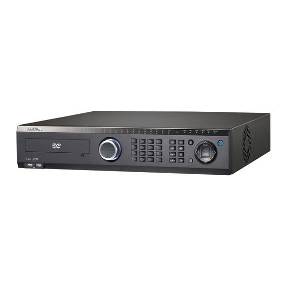
Page 15: Front Part
User Manual Front part Classification Function For copying recorded video and images to DVD/CD DVD-Multi for copying optical media. (Exception: The SVR-945 uses an external copy device.) Channel LED Shows the data input and event operation status Jog can adjust setting values, control the STEP function, navigate through the menu, and adjust the JOG/SHUTTLE playback speed and direction. - Page 16 User Manual AUTO Starts or stops user defined sequences. Starts or ends PTZ function. MONITOR SVR-3200/1680 : Cycles through from Monitor 1 to 4. SVR-1660/1645/960/945 : Switches from main and sub monitor MENU Navigates into the Menu. SEARCH Starts Search mode. COPY Starts Copy mode.
-
Page 17: Rear Part
User Manual Rear Part Input/Output terminal Function name POWER IN Socket for AC 100V ~ AC 240V power cord. CH1 ~ 32 (16/9) Connection terminal for camera BNC input. SVR-3200: 32 ea., SVR-960/945: 9 ea. LOOP OUT Connection terminal for camera BNC output (loop). MONITOR 1 ~ 4 Connection terminal for monitor BNC output. -
Page 18: Osd Menu Structure
User Manual Input/Output terminal Function name Serial Port (Terminal Block) RS-232C D-SUB connector. RELAY OUT Connection terminal for relay output. SENSOR IN Connection terminal for sensor input. AUDIO IN(D-SUB) Connection terminal for audio output D-SUB. D-I/O Connection terminal for DIGITAL IN/OUT. Refer to detailed description for installation &... -
Page 19: Function Menu
User Manual Function Menu The function menu allows the users to access any and all functions and operations of the product with the mouse. To execute a particular function, left-click the icon. Also, all functions listed in the function menu can be executed in full-screen mode. - Page 20 User Manual Resolution Time UTC 00:00 Dublin MM/DD/YYYY Current Time Language English Screen Setup Screen Channel Number Ch 1 Title Cam 1 Activity Color Color Enabled Brightness Contrast PTZ Home PTZ Idle Time PTZ Port None Address Monitor Monitor Number Main Monitor (Monitor 1) Switch to Event Screen...
- Page 21 User Manual Macro Disabled Speed 1 fps Quality Resolution Pre Event Post Event Schedule Channel Number Schedule Full Time Macro No Rec. Speed 1/0.75 fps Quality Resolution Special Time No Rec. Event Recording Event Channel Number Type Sensor Text Macro Standard Speed 8 fps...
- Page 22 User Manual Timeout (ms) 1000 Lines D-I/O Select D-I/O Output Output Type Sensor Event Action Select Action Action Duration Action Source Full Time, Uncheck All Event Acton Full Time, Disable Special Time Preset Channel Number Ch 1 Preset Sensor1, Not Set System Event System Event...
- Page 23 User Manual NTP Server Loc. Public NTP Local Server 0.0.0.0 Interval 1 (Hour) Serial Serial Number Com1 Device None Interface RS232 Baud Rate 9600 Parity Bit None Stop Bit Data Bit System Setup System Remote Controller ID DVR ID DVR Alias DVR0 Playback Deinterlace...
- Page 24 User Manual Remote Setup Enable Remote Relay Enable Time Schedule Weekday Start Weekday End Day Start 09:00 Day End 18:00 00:00 – 00:00 Special Time Zone 1 00:00 – 00:00 Zone 2 00:00 – 00:00 Zone 3 00:00 – 00:00 Zone 4 Exception Days >>...
-
Page 25: Chapter 4. Monitoring
User Manual Chapter 4. Monitoring When turned on, the DVR will display visual data from all analog channels on the screen in its monitoring mode. This chapter explains how to use all monitoring modes offered by the DVR. Main Screen The DVR will turn on when connected with an adequate power source. -
Page 26: Basic System Mode
User Manual 4.4.1 Basic System Mode Pressing the [AUTO] button or clicking in the function menu will cause the DVR to cycle through the set channels. Press [MENU] button or click in the function menu to set up sequence period. Go to “Screen Setup”... -
Page 27: Event Screen
User Manual 1. User sequence can define up to 16 channels. 2. The example shown above has defined 6 sequences in the following order: Single (1) Full (16DIV) 4 Partition (4A) Single (5) Single (6) 9 Partition (9A). SVR-960/945 support only up to 9 partition. Event Screen A screen may be set to pop up automatically in case of an event trigger. -
Page 28: Screen Zoom
To access PTZ functions, press [PTZ] button on the front side of the console or press [FUNC] button to cycle through available functions. The following PTZ controllers are supported: PTZ, Keyboard Compatible List 모델명 제조사 SDZ160/330, Samsung SPD SAMSUNG TECHWIN Keyboard SCC3000, Samsung SRX-100B BOSCH AutoDome, TC8560X-4 BOSCH PELCO(P), PELCO(D) PELCO... -
Page 29: Pan/Tilt
User Manual HONEYWELL Honeywell 755/655, HRX-2000, ScanDome2 Sony EVI-D3x SONY VT VPT-4x AD SpeedDome SUNGJIN SungJin SJ372R1’ SAMSUNG ELECTRONICS Samsung SCC641 Panasonic WV-CS850 PANASONIC LG GAC-PT2 Keyboard KBD300A, WGI SPD1800/2600 WEBGATE Inc. MERIT Merit-Lilin FastDome ELMO Elmo PTC200C Canon VC-C4... -
Page 30: Load Preset
Enter button , user can configure and after the configuration, push ESC button or “PTZ” button of the front to be out of menu(But, it can be available only with Samsung SPD protocol) 4.9 Screen Lock This function is implemented to prevent unauthorized users from manipulating the settings. -
Page 31: Chapter 5. Playback
User Manual saying "Screen Locked" will appear and lock the screen. If the user password is set to "Off", then a message saying "Enable user passwords first" will appear instead. Screen Lock will block all button inputs; it must be disabled first to activate other functions. Pressing any button in Screen Lock mode will prompt a user password screen. -
Page 32: Search
User Manual menu will also work. : Press [REW] to modify playback speed in the reverse direction. (x2, x4, x8, x16, x32, x64, x1/2, x1, x2, x4, …) Pressing [REW] during a live visual feed will play the recording beginning from that moment in the reverse direction. Clicking in the function menu will also work. -
Page 33: Calendar Search
Search : Executes the search function. 5.2.2 Calendar Search Use the calendar to simplify the searching process. <SVR-1680/1660/1645> <SVR-960/945> SVR-3200 will display the storage status of the first 16 channels on Monitor1 and the remaining 16 in Monitor2. : Select the year to be searched from with the mouse wheel. -
Page 34: Event Search
Event Channel : Select the channels to search from. SVR-3200 : ch1 - ch32 SVR-1680/1660/1645 : Ch1 - Ch16 SVR-960/945 : ch1 - ch9 : Select the event types to be searched from. Event Type The available options are: All, MD, Sensor and V-Loss 5.2.4 Thumbnail Search... -
Page 35: Copy
User Manual Channel : Select the channel to be searched from. Once selected, use the up/down buttons or the mouse wheel to adjust. Start Time : Input the starting date and time to search from. Once selected, use the left/right buttons to adjust and press [ENTER]. Use the up/down buttons or the mouse wheel to change the values. - Page 36 User Manual Since SVR-945 does not have a built-in DVD-R, please connect an external backup device. Connect the device to a USB or eSATA port, enter the copy menu and select the CD/DVD. A CD/DVD with a [Ext] tag will appear in the media list. Select the device and proceed just as other devices.
-
Page 37: Re4
Mini-Players and Network Mangers. Select the channel and press [ENTER] or left-click to prompt a channel list as shown below. 메모 [kdh1]: 국문에 따라 [SVR-960/945] [SVR-1680/1660/1645] [SVR-3200] 이미지 추가 필요 Type : Select the RE4 using the up/down buttons or the mouse wheel. -
Page 38: Avi
User Manual buttons on the front side of the console or the mouse wheel to adjust. : Input the ending date and time of the recording. Use the up/down buttons on the front side of the console or the mouse wheel to adjust. - Page 39 User Manual Select Disk : Select the medium to copy. Press [ENTER] on Select Disk to select the medium. Start : Start copying. Press [ENTER] or left-click to start copying. : Format unformatted USB memory devices and HDDs as FAT32. FAT32 Format Press [ENTER] or left-click to start formatting.
-
Page 40: Chapter 6. Configuration
User Manual Chapter 6. Configuration 6.1 Record Setup The DVR offers four recording modes and their setting structure can be seen in the diagram shown below. Refer to their individual entries for detailed explanation. 6.2 System Time Setup Before recording, the system time must be set up. It is critical that the system time is synchronized with the local time, as it may affect data preservation. -
Page 41: Configuring System Time
User Manual 6.2.1 Configuring System Time Changing the system time after files have been recorded and saved will affect the time data of the recordings. Therefore, it is recommended that important visual data are copied before any changes to the system time. Press [MENU] on the front side of the console or click in the function menu. -
Page 42: Camera Setup
User Manual dialogue window as shown below. All setups beside Date and Time will automatically be applied once the menu window is closed. However, as changes in Date and Time may cause critical damages to the HDD file storage system, changes in this menu will not be automatically applied. -
Page 43: Configuring Camera Setup
User Manual 6.3.1 Configuring Camera Setup After pressing [MENU], use the directional buttons or the mouse wheel to go to "Channel" menu under "Screen" menu and select the channel to be configured. 6.3.1.1 Title The camera’s name can be configured. Pressing [ENTER] or left-clicking will pop up the text input window. -
Page 44: Quick Recording Setup (Quick Setup)
User Manual 6.3.1.5 Brightness / Contrast It can control Brightness & Contrast of image. After pressing [ENTER], press the left/right buttons or the mouse wheel to choose between "On" and "Off". 6.3.1.6 PTZ This option configures settings regarding the PTZ device, including PTZ Home, Idle Time, Port and Address. -
Page 45: Configuring Quick Recording Setup
User Manual 6.4.1 Configuring Quick Recording Setup Select ‘Quick Setup’. Recording Schedule There are five options for this entry. The default value is "No Rec." and therefore will not record on schedule without configuration. No Rec. / Low / Standard / High / Custom Except for "Custom", all options have preset fps, screen quality and resolution associated with them. -
Page 46: All Channels
User Manual 6.5.1 All Channels This menu resembles Quick Setup in that changes in this menu apply to all analog channels. Set Channel to "All", set Schedule to "All" and set Macro to Low, Standard or High. 6.5.2 Individual Channels Individual channels may be assigned different recording schedules and macros. -
Page 47: Configuring Event Recording
User Manual There are 5 options total: No Rec./Low/Standard/High/As Above Event Recording Press [ENTER] and use the left/right buttons or the mouse wheel to choose "Yes" or "No". Advanced event recording conditions can be set in the Event Recording menu. In this menu, only whether or not the function will be enabled can be configured. -
Page 48: Configuring Event Recording For All Channels
User Manual 6.6.1.2 Motion Detection Setup This menu is used to configure motion detection for the purpose of event recording for each channel. Motion Detection There are 12 levels of motion detection sensitivity: Min., 1, 2, 3, 4, 5, 6, 7, 8, 9, 10, Max. 6.6.1.3 Text Setup This menu is used to configure text events for the purpose of event recording and the text must set up in "Event Setup"... -
Page 49: Setup By Channel
User Manual Sensor/MD/Text Assign sensor/motion detection/text events for each channel. Assignment means a one-to-one pairing between a channel and an event. 6.6.2.1 Setup by Channel Event Source There are 16 event sources for sensor event (9 for SVR-960/945), 1 for motion detection and 1 for text. -
Page 50: Manual Recording Setup
User Manual Pre-Event (sec) Up to 5 seconds Post-Event (sec) Up to 60 seconds 6.6.3 Manual Recording Setup This menu is used to configure recording sequences initiated by pressing [REC] on the front side of the console. Starting a manual recording will ignore the regular settings and follow by values set in "Manual"... -
Page 51: Audio & Misc. Setup
User Manual Post-Event (sec) Determines the length of time the recording will continue after the user presses [REC]. Up to 60 seconds. 6.7 Audio & Misc. Setup This menu is used to configure audio and v-loss storage setups. 6.7.1 Audio Options such as Audio Channel, Recording, Gain and Sync Video Channel can be adjusted in this menu. -
Page 52: Audio Mix
User Manual 6.7.2 Audio Mix Select the audio input to be used with live visual feed. If set to "All", all audio data will play simultaneously regardless of which channel is being viewed. If set to a particular channel, the audio data assigned to that channel will play regardless of which channel is being viewed. - Page 53 User Manual Monitor1 & Monitor2, Monitor3 & Monitor4 (SVR-3200/1680) Monitor1 supports all functions supported by the DVR. Monitor2, 3 and 4 support all functions except for playback and search. Monitor1 & Monitor2 (SVR-1660/1645/960/945) Monitor1 supports all functions supported by the DVR. Monitor2 supports Event Pop-up, User Sequence and Screen Partition.
-
Page 54: Event Setup
User Manual from 1 to 60 seconds in this menu. Multi Screen Definition This menu defines the screen compositions 4E, 9B and 10A in advance. For SVR-960/945, only 4E is defined. To define a screen composition, select the composition to be defined, select the window to its right and press [ENTER] or use the mouse wheel to open the window. - Page 55 - Channel Channel can be set to All or as follows: SVR-3200 : 1 - 32CH SVR-1680/1660/1645 : 1 - 16CH SVR-960/945 : 1 - 9CH - Sensitivity There are 12 levels of detection sensitivity: Min, 1 - 10, Max.
-
Page 56: Text
User Manual Partitions which have been set to detect changes in motion will be grayed out. Use the directional buttons to select the desired partitions and press [ENTER] or left-click. Once the area has been defined, press [ESC] or right-click to return to the previous screen. 6.9.2 Text Recording This option can be set to either On or Off. -
Page 57: D-I/O
User Manual The Lines option below determines the number of text lines a single piece of information may use. However, despite the standardizations, some pieces of information may be shorter or longer than the others. For example, a customer may only use their first and last name when the ATM provdies three lines for first, middle and last names. -
Page 58: Event Action
User Manual 6.9.4 Event Action Event Action coordinates consequent actions triggered by events. Select Action Event Action may be set to Relay1 through 4, Buzzer or E-Mail. Action Duration Action Duration determines the length of time the specified action will be maintained for Relays and Buzzer. -
Page 59: Network
User Manual 6.9.5 Network This menu is used to configure the networking options of the DVR. Type This option configures the type of network connection (Ethernet/xDSL) the DVR is connected to. If the DVR's connection is leased, cable or LAN, this option must be set to "Ethernet". If the DVR is connected to a PPPoE type xDSL connection, the option must be set to "xDSL". -
Page 60: Xdsl
User Manual same range to communicate with each other. Net Mask must be assigned by the network administrator. Gateway To communicate through an IP address, Gateway must be assigned by the network administrator and configured. DNS1 DNS1 is required to register the DVR to SWR. Consult the network user to configure this option. Additional DNS Additional DNS is used when the primary DNS is unreachable or unstable. -
Page 61: Ddns
User Manual User ID/Password If the DVR is connected to an xDSL line, the user ID and password need to be configured. Status Displays the connection status of the DVR. 6.9.7 DDNS If the DVR is connected to a cable modem or an xDSL modem, a new IP address will be assigned each time the device connects to the ISP. - Page 62 User Manual - SIGN UP page: check ID availability 2) Register the product after sign up. - Log on to iPOLiS website - Product List (If you didn’t register products, there are no list)
- Page 63 User Manual - Product Registration (Check ID availability) - Information regarding the registered products may be reviewed from the list 3) Configure the product for DDNS...
- Page 64 User Manual From the DVR's Network Setup menu, configure the settings as shown below. Select Menu and Network to prompt a screen similar to the illustration shown below. Set DDNS to "On" and input the DDNS address in 'DDNS SERVER DOMAIN NAME'. (The default value is www.samsungipolis.com.) For ID and PW, use the user ID (domain) and password used in iPOLiS product registration process.
-
Page 65: Ntp
User Manual Interval To maintain continuous registration status, a registration cycle must be assigned from "Interval". A dynamic IP address will renew the relevant data from the DDNS per each interval. If the user sets the registration interval to "Disabled" or the DVR does not upload any information over two days, information regarding the DVR will be removed from the DDNS database. -
Page 66: Serial
User Manual Sync with NTP The NTP function may be set to "On" or "Off". NTP Mode The DVR's NTP mode may be set to Client, Server or Both. NTP Server Loc. If the NTP Mode is set to "Client", NTP Server Location will be set to "Enable". It determines the presences of the NTP server within the local or public network. -
Page 67: System Setup
User Manual Serial port Select the port used to control an external device. Device Select the device connected to the DVR. Interface This menu is used to configure the type of interface to be used.COM1 and COM3 are fixed to RS-232C, COM2 is fixed to RS-422/485 and COM4 is fixed to RS-485. - Page 68 User Manual Remote Controller ID Up to 16 RC IDs may be configured. Up to 16 DVR consoles may be controlled by a single remote controller. To register a remote controller, follow the instructions shown below. Point the remote controller at the DVR. Press the ID button corresponding with the RC ID. If the RC's ID and the DVR's ID match, the DVR will buzz.
-
Page 69: Disk Setup
User Manual Load Configuration This menu is used to load the configuration values from a USB device and apply them to the DVR. Save Configuration This menu is used to save the current configuration values in the USB device. Default This menu is used to restore factory default. - Page 70 User Manual Block Playback This function is used to play small sections of visual data recorded on the hard disk space. For example, out of 10 days of recording, only two days of video may be played with Block Playback. Disk Manager Disk Manager is used to manage both internal and external HDDs connected to the DVR.
-
Page 71: Security
User Manual To change HDD usage to Yes - Selecting "No" and pressing [ENTER] or using the mouse wheel will prompt the following notice: - “Warning: This disk can be used without formatting. Would you like to format this disk?” - Select "No"... - Page 72 User Manual On the contrary, the user can use limited functions when the confirmations at authority are “O”. If the user1 configure the unit as above, the user1 can use upto relay Off, power On, N/mic function while the user2 can use the mic function only. Same method is applied upto user10. Admin Password Default administrator password is “11111111”...
-
Page 73: Time Schedule
User Manual Password input window pops up. Type the password and click on “change”button. Y/N window pops up and click on”Y” to continue changing. Changing Password is completed. Using authority Password is identified and usable. When the function to use is executed, password window pops up. -
Page 74: Special Time
User Manual Weekday Start/End Select the first and the last days of the week. Days outside the range are considered to be weekend. Day Start/End Use the up/down buttons to define the beginning and ending of the daytime. Hours outside the range are considered to be night. -
Page 75: Exit
User Manual This function is used to define irregular special time ranges. Up to 30 exception days may be configured and each may be specified to Start Date & Hour, Duration and Profile. : Displays the starting date and time of the exceptions. Start Date &... - Page 76 User Manual Save Select this to save the changes to the DVR configuration and exit the menu. When a dialogue window appears, select "Yes" to save the changes and exit and select "No" to exit without saving. Do not Save Select this to exit the menu without saving any changes.
-
Page 77: Chapter 7. Web Viewer
User Manual Chapter 7. Web Viewer Web Viewer is a web application provided as a complement for the DVR, capable of receiving visual live feeds and playing recorded data from a distance over the Internet. Web Viewer's structure consists of the log-in page, monitoring monitor and playback monitor. Detailed descriptions of the components are as follow. -
Page 78: Connection User Setup
User Manual 7.3 Connection User setup To log into Web Viewer, the user ID and password must be entered to Network Manager's Configuration Tool. Up to 1 administrator and 10 regular user IDs and passwords may be issued. For security purposes, the administrator and regular passwords must be distinct. -
Page 79: Supported Browser
User Manual After the accounts have been configured, assign authority levels for each account. To allow playback access, check "Hard" under the user's account in Configuration Tool. Also, to allow accesses to "Microphone", "PTZ", "Relay", etc., check the relevant boxes and apply the changes. -
Page 80: Moving Playback
User Manual Using the buttons shown above, the partition mode may shift from Single, 4, 9, 13 and 16 partitions. Clicking the monitoring area will change the partition mode to Single. Double-click the channel to expand into Single partition mode. The screen will expand into Single partition. -
Page 81: Sensor Indication
User Manual The above illustration displays the result of toggling Ch.8 and 9 off. When turned off, buttons will change color and the corresponding screen will fade to black. Deactivated buttons are channels not supported by the DVR model. 7.5.4 Sensor indication This icon indicates that a sensor has been triggered. -
Page 82: Event Data
User Manual 7.5.7 Event Data A real-time log of event information is displayed below the monitoring page. Items found in this log are as shown below. (Table Event Icon) Button Function Change setup Motion detection Sensor Relay On V-loss Text Input User Login 7.5.8 Video Recording &... -
Page 83: Ptz Use
User Manual from and select "Save As". To confirm the saving operation, go to the directory the image is saved to and double-click the image. 7.5.9 PTZ Use While monitoring, right-clicking on a channel supporting PTZ and selecting "PTZ" will allow the user to manipulate the camera position. -
Page 84: Audio Use
User Manual 7.5.10 Audio Use If a channel is paired with an audio channel, right-clicking the visual and selecting "Listen" from the pop-up menu will activate audio input. Also, to listen to the audio signal, Mute also needs to be unchecked. 7.5.11 Image Channel Close Clicking the channel buttons to the left of the screen will disconnect the visual connection and fade to black. -
Page 85: Screen Division & Channel Change
User Manual 7.6.1 Screen Division & Channel Change Playback supports 1, 4, 9 and 16 Partition modes. Use the menu (shown above) at the top of the page to choose a partition mode. When the monitoring screen is displaying Channel 1 through 4 in 4 Partition mode, clicking ">>"... -
Page 86: Channel On/Off
User Manual 7.6.5 Channel On/Off This function is identical to the Web Monitor counterpart. The Channel On/Off buttons are at the right side of the page and clicking them will turn the channels on and off. The default value is On. Deactivated channel buttons are not supported by the DVR model. 7.6.6 Recording Duration &... - Page 87 User Manual ⑥ Toggles DirectX usage. If enabled, the video will be drawn with DirectDraw and improve the quality depending on the PC's specification. ⑦ Controls the volume...
-
Page 88: Trouble Shooting
User Manual Trouble Shooting 1. DVR is not booting up Check the power supply Check the power cord 2. Monitor won’t display anything Check the monitor’s power supply Check the connection between the DVR and the monitor Check the monitor’s cable port Check whether DVR is turned on If the images are in black and white, check the camera type (NTSC/PAL) and reboot... - Page 89 User Manual Check the remote’s ID Check the remote’s specification 8. The buttons aren’t working Check the DVR’s power supply Check the Screen Lock setting 9. The DVR won’t connect to the network Check whether the network cable is connected properly Check the DVR’s IP Check the PC’s IP Ping Test...
-
Page 90: Compatible Hdd List
Specification Item Description Display SVR-3200 : 32 composite video 0.5–2 Vpp, 75 ohm automatic termination SVR-1680/1660/1645 : 16 composite video 0.5–2 Video Inputs Vpp, 75 ohm automatic termination SVR-960/945 : 9 composite video 0.5–2 Vpp, 75 ohm automatic termination Resolution... - Page 91 User Manual SVR-3200 : 480fps@704x480, 960fps@704x240, Record Rate/NTSC 960fps@352x240 SVR-1680 : 480fps@704x480, 480fps@704x240, 480fps@352 x 240 SVR-1660/1645 : 120fps@704x480, 240fps@704x240, 480fps@352x240 SVR-960/945 : 120fps@704x480, 240fps@704x240, 270fps@352x240 SVR-3200 : 400fps@704x576, 960fps@704x288, 960fps@352x288 SVR-1680 : 400fps@704x576, 400fps@704x288, 400fps@352x288 메모 [kdh6]: 국문에 없는...
- Page 92 Sub Composite Sport : SVR-1660/1645/960/945(event Pop-up, Display switching), 1 Vp-p, 75 ohm SVR-3200 : None Loop Outputs SVR-1680/1660/1645 : 16 Output, 1 Vpp, 75 ohm SVR-960/945 : 9 Output, 1 Vpp, 75 ohm SVR-3200/1680/1660/1645 : 16 input, 30k ohm Audio Inputs...
- Page 93 SVR-3200/1680/1660 : External eSATA 2 port eSATA SVR-1645/960/945 : External eSATA 1 port Application Support ATM/POS, Mouse, Remote Controller Dome Samsung Techwin, Pelco D, Pelco P, Panasonic, Supported PTZ cameras Protocols Bosch, SEC General 100 to 240 VAC ±10%; 50/60 Hz, Auto-ranging...
-
Page 94: Dimensions
User Manual Dimensions SVR-3200, SVR-1680, SVR-1660, SVR-1645... - Page 95 User Manual SVR-960...
- Page 96 User Manual SVR-945...
- Page 97 User Manual...
Need help?
Do you have a question about the SVR-1680 and is the answer not in the manual?
Questions and answers