Samsung SVR-3200 User Manual
Hide thumbs
Also See for SVR-3200:
- User manual (104 pages) ,
- Install manual (75 pages) ,
- Quick manual (2 pages)
Table of Contents
Advertisement
Quick Links
Advertisement
Table of Contents

Subscribe to Our Youtube Channel
Related Manuals for Samsung SVR-3200


Summary of Contents for Samsung SVR-3200
- Page 1 User Manual...
-
Page 2: Product Warranty And Limits Of Responsibility
Introduction Thank you for choosing Samsung DVR products. This is the user manual for SVR-3200, SVR-1680C, SVR-1660C, SVR-1645, SVR-960C, SVR- 945, SVR-480. Before installing or operating this product, please familiarize yourself with this user manual and other manuals referenced by this manual. - Page 3 All installation operations should be performed by the agency you purchased this product from. This manual is authored SVR-3200, SVR-1680C, SVR-1660C, SVR-1645, SVR-960C, SVR-945, SVR-480 according to firmware version 1.4.0, Content of this manual can differ by Firmware or Software upgrade, and standard and...
-
Page 4: Table Of Contents
Explaining the Symbols ....................7 Chapter 2. Summary ..............10 Features ........................10 Chapter 3. Product Description ........... 14 Front Part ........................14 3.1.1 SVR-3200 ......................14 3.1.2 SVR-1680C, SVR-1660C, SVR-1645 ..............16 3.1.3 SVR-960C ......................18 3.1.4 SVR-945 ......................20 3.1.5... - Page 5 User Manual Live Video Pause ......................40 PTZ Control ........................41 4.7.1 Pan/Tilt ....................... 42 4.7.2 Zoom/Focus ....................... 42 4.7.3 Load Preset ......................42 4.7.4 Save Preset ......................42 4.7.5 Auxiliary On ......................42 4.7.6 Auxiliary Off ......................43 4.7.7 Menu ........................
- Page 6 User Manual 6.6.1 Audio ........................68 6.6.2 Audio Mixing ....................... 69 General Event Setup ..................... 69 6.7.1 Text Setup ......................71 6.7.2 Preset ......................... 72 6.7.3 Digital I/O ......................73 6.7.4 Event Action ....................... 74 Network ......................... 76 6.8.1 xDSL ........................78 6.8.2 DDNS .........................
- Page 7 User Manual 7.6 Playback .......................... 106 7.6.1 Screen Division & Channel Change ..............106 7.6.2 Image Recording ....................107 7.6.3 Print ........................107 7.6.4 Move to Web Monitor ..................107 7.6.5 Channel On/Off ....................107 7.6.6 Recording Duration & Recording Size Check ..........108 7.6.7 Calendar Search ....................
-
Page 8: Chapter 1. Safety Cautions
User Manual Chapter 1. Safety Cautions 1.1 Explaining the Symbols Warning Refers to information users need to know in order to prevent serious injury or death. Before installation Verify the supplied voltage (AC100V~AC240V) before connecting to the power supply. Make sure the power supply is off before installation. Do not install in a very humid environment. -
Page 9: Fcc Compliance Statement
This product is a supplementary rather than primary means for preventing fire and theft. Our company is not responsible for accidents or damage that may occur. Samsung Techwin recommends the installation of a UPS (Uninterrupted Power Supply) with all its recording products. - Page 10 User Manual protection against harmful interference when the equipment is operated in a commercial environment. This equipment generates, uses, and can radiate radio frequency energy and, if not installed and used in accordance with the instruction manual, may cause harmful interference to radio communications.
-
Page 11: Chapter 2. Summary
32/16/9 channels to its built-in hard disk. The buttons on the front of the unit as well as the mouse and GUI allow easy setup and operation. The Samsung SVR series of digital video recorders (DVRs) provide additional safety and security to banks, apartment buildings and complexes, government offices as well as other public, private and commercial facilities. -
Page 12: Video Recording
Per-second frame rates (up to 30 frames per channel) are user customizable SVR-3200 Half D1 : NTSC (704x240) 960fps, PAL (704x288) 800fps SVR-1680C D1 : NTSC (704x480) 480fps, PAL (704x576) 400fps SVR-1660C/1645 CIF : NTSC (352x240) 480fps, PAL (352x288) 400fps... - Page 13 User Manual backed up or stored to DVD-R, CD-R or a USB storage device. The built-in hard disk is provided as primary storage Multiple portable data storage media are supported: DVD-R, CD-R and USB ※ Refer to the appendix on the back of the manual regarding compatible media types.
- Page 14 User Manual Networking The product supports LAN, xDSL and other networking capabilities. Combined with the PC interface client, the core features of the device can be easily remotely controlled. E-mails can be sent via TCP/IP or DHCP upon an event trigger Remote live visual feed (single or 4 section split-screen) PC playback, storage, search and DVR control functions via Network Viewer Remote recording, search and playback scheduling...
-
Page 15: Chapter 3. Product Description
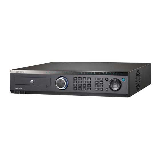
User Manual Chapter 3. Product Description Front Part 3.1.1 SVR-3200 Classification Function DVD-Multi for For copying recorded video and images to DVD/CD copying optical media. Channel LED Shows the data input and event operation status Jog can adjust setting values, control the STEP function,... - Page 16 User Manual COPY lamp Indicates copying operation. PLAY lamp Lit when copying. Power button Turns on or off the device. ESC button The Escape button navigates up the menu tree and closes dialog windows. COPY Starts Copy mode. FUNC Starts Function mode. MONITOR Cycles through from Monitor 1 to 4.
-
Page 17: Svr-1680C, Svr-1660C, Svr-1645
User Manual 3.1.2 SVR-1680C, SVR-1660C, SVR-1645 Classification Function DVD-Multi for For copying recorded video and images to DVD/CD copying optical media. Channel LED Shows the data input and event operation status Jog can adjust setting values, control the STEP function, JOG/SHUTTLE navigate through the menu, and adjust the playback speed and direction. - Page 18 User Manual closes dialog windows. COPY Starts Copy mode. FUNC Starts Function mode. MONITOR Cycles through from Monitor 1 to 4 : SVR-1680C, Switches from main and sub monitor : SVR-1660C, SVR-1645 Starts or ends PTZ function. USB ports for external devices (mouse, USB memory USB1, USB2 stick).
-
Page 19: Svr-960C
User Manual 3.1.3 SVR-960C Classification Function DVD-Multi For copying recorded video and images to DVD/CD copying optical media. Channel LED Shows the data input and event operation status Channel button Selects channel in live feed or playback AUTO Starts or stops user defined sequences. MULTI Changes split-screen sections for live video feeds or playback. - Page 20 User Manual MONITOR Switches from main and sub monitor Starts or ends PTZ function. USB ports for external devices (mouse, USB memory USB1, USB2 stick). PLAY/ENTER Start playback or select an item on the menu. Navigates or selects in the menu, or for playback, ◀/REW changes the reverse playback speed.
-
Page 21: Svr-945
User Manual 3.1.4 SVR-945 Classification Function Channel LED Shows the data input and event operation status Channel button Selects channel in live feed or playback AUTO Starts or stops user defined sequences. MULTI Changes split-screen sections for live video feeds or playback. - Page 22 User Manual Starts or ends PTZ function. USB ports for external devices (mouse, USB memory USB1, USB2 stick). PLAY/ENTER Start playback or select an item on the menu. Navigates or selects in the menu, or for playback, ◀/REW changes the reverse playback speed. Navigates or selects in the menu, or for playback, ▶/FWD changes the forward playback speed.
-
Page 23: Svr-480
User Manual 3.1.5 SVR-480 Classification Function DVD-Multi For copying recorded video and images to DVD/CD optical copying media. Channel button Selects channel in live feed or playback Channel LED Shows the data input and event operation status AUTO Starts or stops user defined sequences. MULTI Changes split-screen sections for live video feeds or playback. - Page 24 User Manual dialog windows. COPY Starts Copy mode. FUNC Starts Function mode. MONITOR Switches from main and sub monitor Starts or ends PTZ function. PLAY/ENTER Start playback or select an item on the menu. Navigates or selects in the menu, or for playback, changes ◀/REW the reverse playback speed.
-
Page 25: Rear Part
User Manual Rear Part 3.2.1 SVR-3200 Input/Output Function terminal name POWER IN Socket for AC 100V ~ AC 240V power cord. CH1 ~ 32 Connection terminal for camera BNC input. MONITOR 1 ~ 4 Connection terminal for monitor BNC output. -
Page 26: Svr-1680C, Svr-1660C, Svr-1645
User Manual AUDIO IN(D-SUB) Connection terminal for audio output D-SUB. D-I/O Connection terminal for DIGITAL IN/OUT. 3.2.2 SVR-1680C, SVR-1660C, SVR-1645 Input/Output Function terminal name POWER IN Socket for AC 100V ~ AC 240V power cord. CH1~16 Connection terminal for camera BNC input. LOOP OUT Connection terminal for camera BNC output (loop). -
Page 27: Svr-960C
User Manual SENSOR IN Connection terminal for sensor input. AUDIO IN(D-SUB) Connection terminal for audio output D-SUB. D-I/O Connection terminal for DIGITAL IN/OUT. 3.2.3 SVR-960C Input/Output Function terminal name POWER IN Socket for AC 100V ~ AC 240V power cord. GROUND Ground terminal between DVR and external device. -
Page 28: Svr-945
User Manual AUDIO IN(D-SUB) Connection terminal for audio output D-SUB. D-I/O Connection terminal for DIGITAL IN/OUT. 3.2.4 SVR-945 Input/Output Function terminal name CH1~9 Connection terminal for camera BNC input. LOOP OUT Connection terminal for camera BNC output (loop). MONITOR 1 ~ 2 Connection terminal for monitor BNC output. -
Page 29: Svr-480
User Manual GROUND Ground terminal between DVR and external device. POWER IN Socket for AC 100V ~ AC 240V power cord. 3.2.5 SVR-480 Input/Output Function terminal name GROUND Ground terminal between DVR and external device. CH1~4 Connection terminal for camera BNC input. LOOP OUT Connection terminal for camera BNC output (loop). -
Page 30: Osd Menu Structure
User Manual Refer to detailed description for installation & use from “Install Manual”. OSD MENU structure The menu structure is as shown below. For detailed instructions for configuration, please refer to Chapter 4, 5 and 6. -
Page 31: Function Menu
User Manual Function Menu The function menu allows the users to access any and all functions and operations of the product with the mouse. To execute a particular function, left-click the icon. Also, all functions listed in the function menu can be executed in full-screen mode. - Page 32 User Manual MM/DD/YYYY Current time Display Setup Channel Channel Number Display Title Cam 1 Status Enable Color Color Enable Brightness Contrast Monitor Monitor Number Main Monitor (Monitor 1) Covert Channel Deselect All Sequencing Number 1 is set to Channel 1 and Number 2 is set to Channel 2 in order.
- Page 33 User Manual Channel Audio Mix Mix On Program ¡¡ CIF, 0fps, Q1 Event Setup Event Event Check Always Event Screen /Dwell Monitor 1 time Event Action Relay 1 Action 10 sec. Duration Normal Event Deselect All Source System Event Deselect All Source Normal Event...
- Page 34 User Manual IP addr Default IP Net Mask Default NM Gateway Default GW DNS1 0.0.0.0 Additional DNS 0.0.0.0 Port 4000 BandWidth Limit(Mbps) xDSL User ID ¡¡ guest Password ***** Status xDSL not connected. Port 4000 Bandwidth Limit (Mbps) DDNS Interval www.samsungipolis.com Server None...
- Page 35 User Manual Default >> Load/Save Load, >> Configuration Firmware Update >> DVR Alias DVR0 System Log >> I-Frame Interval Auto Time >> Disk Disk Manager >> Disk Status >> Security Change P/W Default value Menu Check X, Admin and User: O Check X, Admin and User: O Relay Off Check X, Admin and User: O...
- Page 36 Half Half Half Half Half Half Half Half Half Half Half Program Half Half Half Half Half Half Half Half Half Half Half Half Half Half Half Half Half Half Half Half Model SVR-1680C SVR-3200 Mode Normal Event Normal Event...
- Page 37 User Manual Program Half Half Half Half Half Half Half Half Half Half Half Half Half Half Half Half Half Half Half Half Half Half Half Half Half Half Half Half Half Half Half Half Half Half Half Half Half Half Half Half...
-
Page 38: Chapter 4. Monitoring
User Manual Chapter 4. Monitoring When power is supplied to the DVR, images from all channels connected via analog are displayed on the screen in monitor mode. This chapter describes all DVR features in monitor mode. Default Display The DVR automatically powers on when the power cord is plugged in. -
Page 39: Default System Mode
User Manual menu. To stop this feature, press the button again or click Auto to toggle it in the Function menu. 4.4.1 Default System Mode Use the button to automatically convert the set channels. Press the [MENU] button to set the dwell time. Alternately, click the button on the Function menu. -
Page 40: Event Screen
User Manual 1. Up to 16 user modes can be defined. 2. In the image above, 6 sequences are defined with single screen (1) full screen (16DIV) 4 channel split-screen (4A) single screen (5) single screen 9 channel split-screen (9A) all being displayed in sequence. The SVR-960C/945 support 9, SVR-480 supports 4 channel split-screen. -
Page 41: Zoom In
User Manual 1. If Event Screen is set to Off, event popups will not work. 2. If Event Screen is set to On, the popup image remains displayed until a button is pressed. To return to the previous screen, press any button. Zoom In To zoom in on an image, press the [FUNC] button in single display full screen mode, select the... -
Page 42: Ptz Control
Available PTZ and keyboard models are as shown below. Model Maker SDZ160/330, Samsung SPD SAMSUNG TECHWIN Keyboard SCC3000, Samsung SRX-100B BOSCH AutoDome, TC8560X-4 BOSCH PELCO (P), PELCO (D) PELCO Honeywell 755/655, HRX-2000, ScanDome2 HONEYWELL... -
Page 43: Pan/Tilt
User Manual Tokina TOKINA Kodicom KRE KODICOM Nuvico NUVICO Press a channel button. Press the [PTZ] button on the front or click the button on the Function menu. The PTZ menu (Pan/Tilt, Zoom/Focus, Load Preset, Save Preset) will appear. Select the desired menu item and then press the [Enter] button or click. 4.7.1 Pan/Tilt This menu item is used for real-time Pan and Tilt monitoring. -
Page 44: Auxiliary Off
This is used to enter the console menu of the connected PTZ device. The console menu can be set with the navigation keys and the [Enter] button on the front. After settings are done, press the [ESC] button or the [PTZ] button on the front to exit the console menu (available only with the Samsung SPD protocol). -
Page 45: Playback Mode
User Manual Chapter 5. Playback Playback Mode 5.1.1 Playback on Default Display (16/9/4 channel split-screen) Press the [PLAY] button or click the button on the Function menu in monitoring mode. Press the [PLAY] button or the [FWD] button to play a video at the default 1x speed. Press the [REW] button to play a video in reverse at the default 1x speed. -
Page 46: Search Mode
User Manual : Pressing the [FWD] button while paused plays the video frame by STEP FORWARD frame. Press the [PLAY] button to return to normal playback. : Pressing the [REW] button while paused plays the video frame by STEP REWIND frame in reverse. -
Page 47: Calendar Search
<SVR-1680C/1660C/1645> <SVR-960C/945> <SVR-480> For the SVR-3200, Monitor 1 displays the recording status from channel 1 to 16 while Monitor 2 displays from channel 17 to 32. : Select a year. You can use the mouse wheel to change the year. -
Page 48: Thumbnail Search
: Select a channel. Event Channel For the SVR-3200, Ch1 ~ Ch32 are available. For the SVR-1680C/1660C/1645, Ch1 ~ Ch16 are available. For the SVR-960C/945, Ch1 ~ Ch9 are available. -
Page 49: Copy
User Manual : Select a channel. Use the up or down arrow key on the front or the Channel mouse wheel to change the value. : Enter a start date and time to start the search from. Use the left or Start Time right arrow key to go to an item, press the [Enter] button and use the up or down arrow key or the mouse wheel to change the value. - Page 50 User Manual The SVR-945 is not equipped with a DVD device so you must connect the unit with an external backup device. Connect an external backup device to the USB or eSATA port, execute copy and select CD/DVD. On the media list, a CD/DVD device whose type is [Ext] is displayed.
-
Page 51: Re4
You can back up videos using HDD or USB storage. You can play them using the mini player or network manager. Select the channel field and use the [Enter] button or the mouse wheel to open the channel list as shown below. [SVR-3200] [SVR-1680C/1660C/1645] [SVR-960C/945] [SVR-480] : Select RE4. -
Page 52: Avi
User Manual [Enter] button or click to select a media. : Start copying. Move to the [Start] button and press the [Enter] button Start or left-click. : Format unformatted USB storage devices or HDDs in FAT32 before FAT32 Format copying. Select the [FAT32 Format] button and press the [Enter] button or left-click. - Page 53 User Manual [Enter] button or click to select media. : Start copying. Move to the [Start] button and press the [Enter] button or Start left-click. : Format unformatted USB storage devices and HDDs in FAT32 before FAT32 Format copying. Select the [FAT32 Format] button and press the [Enter] button or left-click.
-
Page 54: Chapter 6. Setup
User Manual Chapter 6. Setup Record Setup There are 4 DVR recording modes. Their relationship is as shown in the image below, which briefly describes recording modes. For more information on recording, refer to the following sections. Recording Event Recording Schedule Recording Manual Recording Emergency Recording... -
Page 55: How To Set Time
User Manual not recommended to change the time while recording. The factory default time zone is UTC 00:00 Dublin. 6.2.1 How to Set Time If you change the time when recording is already in progress, the time is also changed for existing recorded videos. It is recommended to back up critical video data before changing the time. -
Page 56: Camera Setup
User Manual Apply You must press the [Apply] button to save the Date/Time values. Then, the dialog box below appears. Setups other than "Date/Time" setup are automatically recorded if the menus are completely closed, but "Date/Time" setup is not automatically recorded because it may damage the HDD recording file system. -
Page 57: How To Set A Camera
User Manual 6.3.1 How to Set a Camera Press the [MENU] button and use the navigation keys or the mouse wheel to select a desired channel from the "Channel" menu under the "Display" menu of Display Setup. Title Specify the camera name. Press the [Enter] button or click to open the character input menu. -
Page 58: Monitor Setup
Monitor Setup This menu is used to set related items when displaying a video on the monitor. Monitor 1 & Monitor 2~4 (SVR-3200/1680C/1660C) Monitor 1 is available for all supported functions of the DVR while Monitor 2~4 are available for all functions other than playback and search. -
Page 59: Record Setup
User Manual Monitor 1 is available for all supported functions of the DVR while Monitor 2 is available for event popup, user sequencing and split screen. Covert Channel This menu is used to hide channels in live mode. The Covert Channel menu shows the unit's channel list. Press the [Enter] button or click to select a channel. -
Page 60: Program Setup
User Manual 6.5.1 Program Setup Using the [Program] menu, you can set up a program to use for both Manual & Event and Schedule & Event. You can adjust the frame rate, video quality and resolution of the program. Two choices are available: 1) Select a program by the frame rate, quality, and resolution, or 2) Set up a program manually. - Page 61 User Manual Q (Quality) Indicates the recording quality: Q5, Q4, Q3, Q2, and Q1. For Event Recording, Q3 or higher is recommended. Max R/F Indicates the maximum frame rate available for a selected resolution. For instance, CIF 30fps means that you can select up to 30fps for the CIF resolution of a selected channel. D1 30fps means that you can select up to 30fps for the D1 resolution.
- Page 62 User Manual • Event Settings in and CIF 480fps Recording Performance When every channel is set up to record normally at CIF 30fps, the Event Recording settings of for 1 channel are limited to CIF 30 fps, Half 15 fps, and D1 7fps. If you want to set the Event Recording settings value to D1 30fps, the Normal Recording settings value of the other channels must be changed to total CIF 360fps or less.
-
Page 63: Manual/Schedule Recording Setup
User Manual Schedule & Event Setup Set record mode to "Schedule & Event" and set a schedule and event for each date and time. How to Check Recording If record setup is properly completed, the 'REC LED' on the front will flicker. Also, [S] is displayed to show that currently all channels are recorded as scheduled. -
Page 64: Manual Recording
User Manual Manual Recording Manual Recording is activated only when the recording mode is set to Manual & Event. After selecting a program, press the [REC] button on the front of the DVR unit to begin recording. If you want to schedule a recording, switch the recording mode to Schedule & Event. Schedule Recording Settings Schedule Recording records video automatically at a scheduled time according to the chosen program settings. - Page 65 User Manual • Index: 1~50 different programs can be set • Day: designate recording date • Program: select a recording program (A~T) • Time: designate recording time • Delete: delete the desired INDEX Setting Method As you set INDEX, DAY, PROGRAM and HOUR, then the content will be immediately displayed in the table.
-
Page 66: Evnet Record Setup
User Manual When you set the region of time, you may not include the existing time that is set previously. Record Setting Repeat Record Mode When there is no more space for recording to hard disk, recorded data is removed from the foremost portion automatically. - Page 67 User Manual Event Recording is used mostly in conjunction with other recording options: Manual & Event and Schedule & Event. Go to [Record Setup] > [Record]. In "Record Mode," select Manual & Event or Schedule & Event. To use Event Recording only, please refer to the following instructions. 1.
- Page 68 User Manual • INDEX : 1~50 different programs can be set • Day: designate recording date • Time: designate recording time • Delete: delete the desired INDEX Setting Method As you set INDEX, DAY, and HOUR, then the content will be immediately displayed in the table. If you select the start time and the stop time for recording in the table and click on them in order, the content will be displayed in INDEX, DAY, and HOUR.
-
Page 69: Audio Setup
User Manual Audio Setup This menu is used to set audio recording, sync or mixing. 6.6.1 Audio This menu is used to set the audio channel, audio recording, audio gain and sync. Audio Channel Select a channel for audio. Audio Recording Decide whether to record audio. -
Page 70: Audio Mixing
User Manual 6.6.2 Audio Mixing This menu is used to select audio for live video feeds. If All is set, all inputted audio is mixed for output regardless of channel selection. If specific audio is selected, only the specified channel is outputted regardless of the channel selection. - Page 71 User Manual Motion Detection This enables each channel or all channels to detect motion and notify users. - Channel Channel can be set to All or as follows. SVR-3200: 1~32CH SVR-1680C/1660C/1645: 1~16CH SVR-960C/945: 1~9CH SVR-480 : 1~4CH - Sensitivity Sensitivity can be set to Lowest, 1~10, or Highest for each channel.
-
Page 72: Text Setup
User Manual detection areas turn gray. To select motion detection areas, use the navigation buttons to select them and press the [Enter] button or click them. Press the [ESC] button or right-click to return to the previous menu. Sensor A total of 16 sensors (9 sensors for the SVR-960C/945, 4 sensors for the SVR-480) can be set. If All is selected, all channels are set to N.O or N.C. -
Page 73: Preset
User Manual Lines This defines the maximum number of lines for one piece of data. An external device may not be recognized depending upon its characteristics, so it is recommended to contact the manufacturer before installation. 6.7.2 Preset This menu is used to activate the presets specified in the PTZ based on sensor input. Specify a preset with PTZ attached to each channel. -
Page 74: Digital I/O
User Manual 6.7.3 Digital I/O Digital I/O are digital ports available for input and output at the same time., There are 12 digital inputs and outputs. Digital I/O Channel & Input/Output All 12 channels can be set to input/output. When channels are set to input, if an input signal is received by even one channel, emergency recording will operate. -
Page 75: Event Action
User Manual 6.7.4 Event Action This sets actions based on event input. Event Action For Event Action, you can select Relay 1~4, buzzer, or E-Mail. Action Duration Action Duration is used to maintain an action for a specified time when relay or buzzer is set. If E-Mail is set, e-mails are sent in specified time intervals. - Page 76 User Manual System Event Source This sets some or all of disk error, disk full, fan error, authentication failure and DDNS registration failure. E-Mail Setup E-Mail address is set when e-mail is used for output. For e-mail address, enter an e-mail address for a message recipient. The address format is xxxx@xxxxxx.xxx.
-
Page 77: Network
User Manual - Attaching Image Files For a Normal event log, the system sends an e-mail attached with an image of the event channel along with the event information including the sensor, movement detection, and object disappearance. For a System event log, the system sends only the event information because the channel pairing option is not available. - Page 78 User Manual This is used to select the network type (Ethernet/xDSL) connected to the DVR. Select Ethernet when the DVR is connected to dedicated line, cable modem or LAN. Select xDSL when the DVR is connected to a PPPoE-type xDSL line. However, if the xDSL line is not of the PPPoE type, you must select Ethernet.
-
Page 79: Xdsl
User Manual Port is used to register to SWR, connect to Network Manager, or connect to Webviewer. The default port is 4000. Be careful about the port entry when a PPPoE modem Internet sharing device are in use. Bandwidth Limit (Mbps) This sets the maximum transmission speed of data outputted from the DVR, or the data transmission capability of the DVR. - Page 80 User Manual server, the DVR's IP may be identified by connecting to the DDNS server. To register a dynamic IP address to a DDNS, follow the instructions shown below. DDNS Registration procedure 1) Sign up at iPOLiS homepage. - The homepage URL is [www.samsungipolis.com] - Accept the terms and conditions, SIGN UP page: check ID availability 2) Register the product after sign up.
- Page 81 User Manual - Product List (If you didn’t register products, there are no list) - Product Registration (Check ID availability), Information regarding the registered products may be reviewed from the list...
- Page 82 User Manual 3) Configure the product for DDNS From the DVR's Network Setup menu, configure the settings as shown below. Select Menu and Network to prompt a screen similar to the illustration shown below. Set DDNS to "On" and input the DDNS address in 'DDNS SERVER DOMAIN NAME'.
- Page 83 User Manual - The Product list will display status 'On' for the connected device [VIEW]: See the log-in page of selected product [Edit]/ [Delete]: Edit/Delete the selected product Once the product has been registered, its ID (domain) may not be changed. When the product’s ID needs to be changed, the product’s registration must be reset.
-
Page 84: Ntp
User Manual A dynamic IP address will renew the relevant data from the DDNS per each interval. If the user sets the registration interval to "Disabled" or the DVR does not upload any information over two days, information regarding the DVR will be removed from the DDNS database. Server This menu is used to configure the server address to be registered. -
Page 85: Remote
User Manual This turns NTP on or off. NTP Mode This sets NTP Mode to Client, Server or All. NTP Server Location This is enabled when NTP Mode is set to Client. This determines whether the NTP server is on a local network or on the Internet. -
Page 86: Serial Port
User Manual Remote Controller ID Up to 16 remote controller IDs can be set. You can use one remote controller to operate up to 16 DVRs. How to register the remote controller is as shown below. Direct the remote controller to the DVR. Press the [ID] button based on the specified remote controller ID. - Page 87 User Manual 6.8.4.1.1 Text To use the Text option, please follow the instructions below. Please note that the Text option supports only Com1 (RS-232); make sure to select Com1 on the Serial Port menu. Device Select Text. Interface Select RS-232. Baud rate/Parity/Stop Bit/Data Bit Enter the same settings as the ones for the selected TP device.
- Page 88 User Manual Device Select a connected transparent device. Interface Select COM1 or COM3. ※ Only Com1 is available for SVR-480. Baud rate/Parity/Stop Bit/Data Bit Enter the same settings as the ones for the selected Transparent device. 6.8.4.1.3 Keyboard To set up a keyboard, select Keyboard for the Device option, and then select a keyboard model. Device Select Keyboard.
- Page 89 User Manual Select COM1 or COM3. ※ Only Com1 is available for SVR-480. Baud rate/Parity/Stop Bit/Data Bit Enter the same settings as the ones for the selected keyboard. 6.8.4.1.4 Select PTZ. To control the PTZ operation via serial port, select PTZ in the Device options, and then set up a serial port;...
- Page 90 PTZ functions. To use this option, a PTZ device must be embedded with a coax standard or extended protocol. ※ SVR-3200, SVR-1645, SVR-945, SVR-480 does not support coaxial function. Type Select Coax.
-
Page 91: System Setup
User Manual Type Select a serial port. Protocol Select a connected PTZ device. Camera ID Enter the ID of the selected camera. Interface Select one from among Com2 to 4. To use RS-232, select Com3. For RS-422 or 485, select Com2 or 4. Baud rate/Parity/Stop Bit/Data Bit Enter the same settings as the ones for the PTZ device. -
Page 92: System Setup
User Manual 6.9.1 System Setup Language The OSD menu supports multiple languages. Select a language. Key Buzzer This determines whether to use the buzzer for the buttons on the front. Default This restores the factory default settings. Press the [Default] button to restore the factory default. Load Configuration This sends the DVR setting stored in a USB storage device to the DVR. - Page 93 User Manual password (default: 11111111) specified in SNM-128S into "Admin Password" and press the [Start Upgrade] button. After the upgrade progress window appears, a message prompting you to reboot the unit is displayed. Select "Yes" to reboot the unit. DVR Alias This sets a DVR alias.
-
Page 94: Disk
User Manual Copying System Log System logs are saved as txt-formatted files, and can be saved to a USB flash drive. To save system logs to a USB drive, insert the drive into a USB port, open the System Log list. And then press the "COPY"... - Page 95 User Manual Disk Manager Disk Manager is used to manage internal and external HDDs. It manages HDD status, bad blocks, size, enabled, disabled, etc. : Displays disk locations and types. Type Int A (Internal A HDD), Int B (Internal B HDD), Ext (External HDD) : Displays HDD models.
-
Page 96: Security
User Manual : Displays HDD sizes in MB. Size(MB) : Enables or disables HDDs. Enabled Yes: Enabled / No: Disabled To change HDD to Yes - Enabled: Select No and press the [Enter] button or use the mouse wheel to open the notice window with the following message. - Page 97 User Manual features without any limitations. The maximum number of users is 10. They can only use features that they have permissions for. Right In Right Setup, if Check is set to all X, all users can use all features without any limitations. If Check is set to all O, each user can use only features for which they have been given permissions.
-
Page 98: Exit
User Manual 10's password is "00000000". The 16 channel-DVRs do not have a [0] (zero) button so they use the [10] (ten) button instead. Change Password As shown in the image below, click Change P/W for a user you want to change. The password input window appears. - Page 99 User Manual Save This saves all settings and exits to the live screen. Select Yes to save all settings and exit, or select No to exit without saving any settings. Do not save This is used to exit without saving any settings.
-
Page 100: Chapter 7. Web Viewer
User Manual Chapter 7. Web Viewer Web Viewer is a web application provided as a complement for the DVR, capable of receiving visual live feeds and playing recorded data from a distance over the Internet. Web Viewer's structure consists of the log-in page, monitoring monitor and playback monitor. Detailed descriptions of the components are as follow. -
Page 101: Connection User Setup
User Manual 7.3 Connection User setup To log into Web Viewer, the user ID and password must be entered to Network Manager's Configuration Tool. Up to 1 administrator and 10 regular user IDs and passwords may be issued. For security purposes, the administrator and regular passwords must be distinct. -
Page 102: Supported Browser
User Manual After the accounts have been configured, assign authority levels for each account. To allow playback access, check "Hard" under the user's account in Configuration Tool. Also, to allow accesses to "Microphone", "PTZ", "Relay", etc., check the relevant boxes and apply the changes. -
Page 103: Moving Playback
User Manual Double-click the channel to expand into Single partition mode. The screen will expand into Single partition. To return to the partition screen, double-click the monitoring area once again. In a partition mode, the placement of screens may be moved around. -
Page 104: Sensor Indication
User Manual 7.5.4 Sensor indication This icon indicates that a sensor has been triggered. When triggered, its corresponding icon will turn red and the sensor ID number will be displayed on the video. Sensors that have not been triggered will remain blue. Deactivated sensor icons are sensors not supported by the DVR model. -
Page 105: Event Data
User Manual 7.5.7 Event Data A real-time log of event information is displayed below the monitoring page. Items found in this log are as shown below. (Table Event Icon) Button Function Change setup Motion detection Sensor Relay On V-loss Text Input User Login 7.5.8 Video Recording &... -
Page 106: Ptz Use
User Manual from and select "Save As". To confirm the saving operation, go to the directory the image is saved to and double-click the image. 7.5.9 PTZ Use While monitoring, right-clicking on a channel supporting PTZ and selecting "PTZ" will allow the user to manipulate the camera position. -
Page 107: Audio Use
User Manual 7.5.10 Audio Use If a channel is paired with an audio channel, right-clicking the visual and selecting "Listen" from the pop-up menu will activate audio input. Also, to listen to the audio signal, Mute also needs to be unchecked. 7.5.11 Image Channel Close Clicking the channel buttons to the left of the screen will disconnect the visual connection and fade to black. -
Page 108: Image Recording
User Manual Playback supports 1, 4, 9 and 16 Partition modes. Use the menu (shown above) at the top of the page to choose a partition mode. When the monitoring screen is displaying Channel 1 through 4 in 4 Partition mode, clicking ">>" button will display the next four channels. To return to the previous four channels, click "<<". -
Page 109: Recording Duration & Recording Size Check
User Manual is On. Deactivated channel buttons are not supported by the DVR model. 7.6.6 Recording Duration & Recording Size Check This menu displays used and remaining spaces in the HDD. It also displays the total recording duration. HDD usage is expressed as a percentage. 7.6.7 Calendar Search Days with recordings are activated as black buttons and days without recordings are gray and deactivated. -
Page 110: Trouble Shooting
User Manual Trouble Shooting 1. DVR is not booting up Check the power supply Check the power cord 2. Monitor won’t display anything Check the monitor’s power supply Check the connection between the DVR and the monitor Check the monitor’s cable port Check whether DVR is turned on If the images are in black and white, check the camera type (NTSC/PAL) and reboot... - Page 111 User Manual Check the remote’s ID Check the remote’s specification 8. The buttons aren’t working Check the DVR’s power supply Check the Screen Lock setting 9. The DVR won’t connect to the network Check whether the network cable is connected properly Check the DVR’s IP Check the PC’s IP Ping Test...
-
Page 112: Compatible Hdd List
Sony(Exhortation 16X) Sony(Exhortation 16X) Specification Item Description Display SVR-3200 : 32 composite video 0.5–2 Vpp, 75 ohm automatic termination SVR-1680C/1660C/1645 : 16 composite video 0.5–2 Vpp, 75 ohm automatic termination Inputs Video SVR-960C/945 : 9 composite video 0.5–2 Vpp, 75 ohm automatic termination SVR-480 : 4 composite video 0.5–2 Vpp, 75 ohm... - Page 113 704x480 NTSC, 704x576 PAL SVR-3200/1680C/1660C/1645 : 1/4/9/10/16 Multi Screen SVR-960C/945 : 1/4/9 SVR-480 : 1/4 Performance Compression MPEG-4 Recording SVR-3200 : 480fps@704x480, 960Cfps@704x240, Record Rate/NTSC 960Cfps@352x240 SVR-1680C : 480fps@704x480, 480fps@704x240, 480fps@352 x 240 SVR-1660C/1645 : 120fps@704x480, 240fps@704x240, 480fps@352x240 SVR-960C/945 : 120fps@704x480, 240fps@704x240, 270fps@352x240...
- Page 114 Maximum Capacity Storage SVR-1645/960C/945/480 : 8 TB SVR-3200/1680C/1660C : 4 HDD Internal HDD SVR-1645/960C/945/480 : 2 HDD SVR-3200/1680C/1660C : External eSATA 2 port External HDD SVR-1645/960C/945/480 : External eSATA 1 port DVD Writer (Back-up) DVD-R / CD-R USB (Back-up) 2 External USB Ports(USB 2.0)
- Page 115 SVR-1645/960C/945/480 : RS485 Via coax cable (SVR-1680C/1660C/960C) PTZ Keyboard RS485, max. signal voltage ±12 V 2 USB 2.0 ports SVR-3200/1680C/1660C : External eSATA 2 port eSATA SVR-1645/960C/945/480 : External eSATA 1 port Application Support ATM/POS, Mouse, Remote Controller Samsung Techwin, Pelco D, Pelco P, Pelco...
- Page 116 User Manual Portuguese, Russian, Turkish, Japanese, Czech, Serbian, Swedish, Rumanian, Danish, Chinese, Korean, Taiwanese...
-
Page 117: Dimensions
User Manual Dimensions SVR-3200, SVR-1680C, SVR-1660C, SVR-1645... - Page 118 User Manual SVR-960C...
- Page 119 User Manual SVR-945...
- Page 120 User Manual SVR-480...
- Page 121 User Manual...
- Page 122 User Manual...
Need help?
Do you have a question about the SVR-3200 and is the answer not in the manual?
Questions and answers