KOBE IS2336SQ Installation Instructions And Operation Manual
Is-123 series – 7” height
Hide thumbs
Also See for IS2336SQ:
- Installation instructions and operation manual (23 pages) ,
- Installation instructions and operation manual (72 pages) ,
- Installation instructions and operation manual (74 pages)

Related Manuals for KOBE IS2336SQ


Summary of Contents for KOBE IS2336SQ
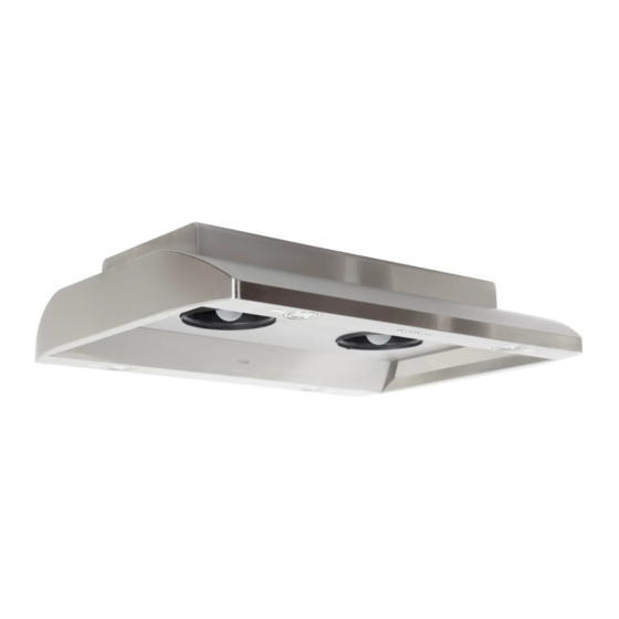
- Page 1 KOBE Brand Range Hood Model No. IS2336SQ IS2342SQ IS-123 SERIES – 7” HEIGHT INSTALLATION INSTRUCTIONS AND OPERATION MANUAL...
-
Page 2: Table Of Contents
- READ AND SAVE THESE INSTRUCTIONS - CONTENTS Important Safety Instructions………………………………………………………………. Components of Package.………………………………………………………………….. Installation…………………………………………………………………………………… Operating Instructions…………………………………...…………………………………. Maintenance…………………………………………………………………………………. Specifications…………………………………………………….……..…………………... Measurements & Diagrams…………………………………………………………...…… Parts List…………………………………………………………………..…………………. Circuit Diagram………………………………………………………………...……………. Disclaimer……………………………………………………………………………………. Warranty…………………………………………………………………...………………… Product Registration………………………………………………………...……………… - READ ALL INSTRUCTIONS CAREFULLY BEFORE STARTING - ALL WIRING MUST BE DONE BY A PROFESSIONAL AND IN ACCORDANCE WITH NATIONAL AND LOCAL ELECTRICAL CODES. -
Page 3: Important Safety Instructions
KOBE RANG E HOODS authorized agents. Any repair carried out without the supervision of KOBE RANGE HOODS authorized agents will automatically void the warranty. - Page 4 What to Do In The Event Of a Range Top Grease Fire SMOTHER FLAMES with a close fitting lid, cookie sheet, or metal tray, and then turn off the burner. KEEP FLAMMABLE OR COMBUSTIBLE MATERIAL AWAY FROM FLAMES. If the flames do not go out immediately, EVACUATE THE AREA AND CALL THE FIRE DEPARTMENT or 911.
-
Page 5: Components Of Package
COMPONENTS OF PACKAGE (Must keep all material for returns or refunds) BOX 1: {A} KOBE Range Hood {B} Mounting Template {C} Warranty Registration Card {D} Instructions Manual ORIGINAL KIT BOX 2 (SOLD SEPARATELY): {E} Telescopic Stack {F} Two-Piece Duct Cover... -
Page 6: Installation
INSTALLATION PLEASE READ ENTIRE INSTRUCTIONS BEFORE PROCEEDING Calculation before Installations To calculate the length of the installation, please refer to Table 1. (All calculation is measure in inches.) TABLE 1 A = Height of Floor to Ceiling B = Height of Floor to Counter Top (Standard: 36”) C = Preferred Height of Counter Top to Hood Bottom (Recommended... - Page 7 Telescopic Stack Installation Note: Duct cover with telescopic stack sold separately. Mark centerlines of cook top or range on ceiling above. Use centerlines marked on ceiling to position the mounting template as shown in Figure 2. Remove and save template. Cut and remove ceiling drywall. Install 2” x 4” cross framing lumber (not provided) between ceiling joists.
- Page 8 Duct Cover Installation Slide the duct cover up and secure the inner duct cover to the telescopic stack with four (4x8 mm) screws (provided). Refer to Figure 5. Hood Installation Place temporary screws to hold the duct cover up. Install the hood as shown in Figure 6. Use eight (3/16x3/8 mm) screws (provided) to secure hood to telescopic stack.
- Page 9 Ductwork Installation Note: Skip this step if installing recirculating kit. 14. Use 6” round pipe to connect the plastic exhaust on the hood to the ductwork above. 15. Use duct tape to make all joints secure and air tight. Final Assembly 16.
-
Page 10: Operating Instructions
Press Power Control (On/Off) button once. (If any Control button is not pressed within 10 seconds, power will be automatically turned off). The KOBE hood will start on Low speed. Each press of the Speed Control button will cycle through the various speeds. -
Page 11: Maintenance
MAINTENANCE CAUTION: NEVER PUT YOUR HAND INTO THE AREA HOUSING THE FAN WHILE THE FAN IS OPERATING. For the optimal level of operation, clean the range hood surface, filter set, and oil containers regularly. To Clean Hood Surface CAUTION: NEVER USE ABRASIVE CLEANERS, PADS, OR CLOTHS. *** Regular care will help preserve its fine appearance. - Page 12 To Replace Light Bulb CAUTION: HALOGEN LIGHT UNIT MAY BE HOT! WAIT UNTIL UNIT IS COOL. 1) Make sure all control switches are off, and range hood is unplugged. 2) Use a flat head screwdriver to pop out the protective covering as shown in Figure 10. 3) Gently pull out the defective light bulb and discard.
-
Page 13: Specifications
10-Second Standby Startup 30-Second Delay Shutoff HALOGEN LIGHTS 12V 20W x 4 HOOD (IS2336SQ) 35-3/4” x 27” x 7” DIMENSION (W x D x H) (IS2342SQ) 41-3/4” x 27” x 7” TELESCOPIC STACK Two-Piece Adjustable Telescopic Stack DIMENSION (W x D x H) 1) Original Kit (Sold Separately): (IS123DC) 11-1/8”... -
Page 14: Measurements & Diagrams
MEASUREMENTS & DIAGRAMS ***All inch measurements are converted from millimeters. Inch measurements are estimated. ***All measurements in ( ) are millimeters. ORIGINAL KIT (Sold Separately) MODEL NO. MAX. HT. INTSALLED IS123DC 18-1/8” 19-1/4” 37-3/8 14-5/8” 22-5/8” 37-1/4” 36-3/8” (460) (490) (950) (370) (575) - Page 15 RECIRCULATING KIT (Sold Separately) MODEL NO. MAX. HT. INTSALLED IS123DCD 18-1/8” 19-1/4” 37-3/8 14-5/8” 22-5/8” 37-1/4” 36-3/8” (460) (490) (950) (370) (575) (946) (925) IS123-16DCD 9-1/4” 8-1/4” 17-1/2” 16” 16” (235) (210) (445) (405) (405) IS123-59DCD 30-1/4” 29” 59-1/4” 25-5/8” 33-5/8”...
-
Page 16: Parts List
PARTS LIST MODEL NO.: IS2336SQ IS2342SQ KEY NO. DESCRIPTION MODEL /SIZE PART NO. Power Cord C1-0406-0120-01 6” Round Plastic Exhaust C1-0505-0001 Round Head Screw (TS 4 x 6) C1-0708-0006 Hood Roof B101-1242-13 Hood Casing IS2336SQ B101-1236-02 IS2342SQ B101-1242-02 Transformer Bracket... - Page 17 MODEL NO.: IS123DC ORIGINAL KIT (Sold Separately) KEY NO. DESCRIPTION MODEL /SIZE PART NO. Duct Cover IS123DC 12-04000-304-51 IS123-16DC 12-04016-304-51 IS123-59DC 12-04059-304-51 Round Head Screw (3/16” x 3/8”) C1-0707-0001 Telescopic Stack IS123DC C1-0203-1242-36 IS123-16DC C1-0203-1242-16 IS123-59DC C1-0203-1242-59 Round Head Screw (3/16” x 3/8”) C1-0708-0001 Duct Cover Screw (3 x 8 mm) C1-0707-0001...
- Page 18 MODEL NO.: IS2336SQ IS2342SQ...
-
Page 19: Circuit Diagram
CIRCUIT DIAGRAM MODEL NO.: IS2336SQ IS2342SQ... -
Page 20: Disclaimer
2. PLEASE INSPECT CONTENTS OF PACKAGE (S) CAREFULLY UPON RECEIVING! We must be notified in writing of any damages and/or missing parts within the allocated days upon receipt of package(s). Contact your local KOBE dealer or distributor or call KOBE for the time limit. -
Page 21: Warranty
WARRANTY WARRANTY CERTIFICATE KOBE Range Hoods, Inc. warrants all products manufactured or supplied by it to be free from defects in workmanship and materials. Its obligations pursuant to this warranty are limited to a period of two years from the date of purchase and to the repair or replacement at its option and subject to the terms and conditions stated below, of any component part, which its examination shall disclose to be so defective. - Page 22 KOBE Range Hoods Agent as applicable, for any traveling expenses and any costs of transporting the range hood or...
-
Page 23: Product Registration
KOBE Range Hoods Agent or KOBE Range Hoods as applicable. Keep proof of purchase (original invoice) handy for inspection.
Need help?
Do you have a question about the IS2336SQ and is the answer not in the manual?
Questions and answers