
Related Manuals for Toshiba 4200 FA CT


Summary of Contents for Toshiba 4200 FA CT
- Page 1 TOSHIBA NINTERRUPTIBLE OWER YSTEM THREE-PHASE 15/25/30/50 kVA UPS 4200FA CT/XT User’s Manual Document Number: 53878-008 Date: May 2008...
- Page 2 TOSHIBA 4200FA CT/XT User’s Manual...
- Page 3 CT-Internal Batteries XT- External Batteries or External Transformer USER’S MANUAL FOR MODELS C42F3F150X#MBN C42F3F150F#MBN C42#3#150##MXN C42F3F250X#MBN C42F3F250F#MBN C42#3#250##MXN T42F3F300X#MBN T42F3F300F#MBN T42#3#300##MXN T42F3F500XAMBN T42F3F500F#MBN T42#3#500##MXN TOSHIBA INTERNATIONAL CORPORATION INDUSTRIAL DIVISION 13131 West Little York Road Houston, TX 77041-9990 4200FA CT/XT User’s Manual...
- Page 4 TOSHIBA 4200FA CT/XT User’s Manual...
-
Page 5: Important Notice
UNINTERRUPTIBLE POWER SYSTEM If additional information or technical assistance is required call TOSHIBA Customer Support Center toll free at 1- 877-876-8773, or write to: Toshiba International Corporation, 13131 West Little York Road, Houston, TX 77041- 9990 Attn: UPS Product Manager. -
Page 6: Purpose And Scope Of Manual
TOSHIBA shall not be liable for technical or editorial omissions or mistakes in this manual. Nor shall it be liable for incidental or consequential damages resulting from the use of information contained in this manual. -
Page 7: Table Of Contents
TOSHIBA TABLE OF CONTENTS TABLE OF CONTENTS..................... i GENERAL SAFETY INSTRUCTIONS................1 EQUIPMENT WARNING LABELS ................... 2 IMPORTANT SAFETY INSTRUCTIONS ................5 Product Description ..................... 9 Theory of Operation ........................9 Application and Use ........................9 Power Backup ..........................9 Power Conditioning ......................... - Page 8 TOSHIBA Front Panel Layout (All Units) ....................... 37 EPO (Emergency Power Off) Function ..................37 6.10 Audible Alarm Functions ....................... 38 6.11 LED (Light Emitting Diode) Functions ................... 38 6.11.1 LED (Light Emitting Diode) System Status................39 6.12 LCD (Liquid Crystal Display) Functions ..................39 6.12.1 Line-1 System Messages ......................
-
Page 9: General Safety Instructions
TOSHIBA GENERAL SAFETY INSTRUCTIONS DO NOT attempt to install, operate, maintain or dispose of this equipment until you have read and understood all of the product safety information and directions that are contained in this manual. Safety Alert Symbol The Safety Alert Symbol indicates that a potential personal injury hazard exists. The symbol is comprised of an equilateral triangle enclosing an exclamation mark. -
Page 10: Equipment Warning Labels
If the labels are damaged or if additional labels are required, contact your TOSHIBA representative for additional labels. The following are examples of the warning labels that may be found on the equipment. The labels are there to provide useful information or to indicate an imminently hazardous situation that may result in serious injury, severe property and equipment damage, or death if the instructions are not followed. - Page 11 TOSHIBA DANGER RISK OF ELECTRIC SHOCK Capacitors stay charged after power has been shut off. Accidental contact with live parts can cause personal injury and death. Turn off and lock out all power sources. Wait at least five (5) minutes for power to dissipate then check voltage before servicing.
- Page 12 TOSHIBA NOTE: This Label for Battery Units Only 4200FA CT/XT User’s Manual...
-
Page 13: Important Safety Instructions
Therefore, a user-installed circuit breaker should be provided between the UPS output and the load input. 3. Battery servicing should be performed by a qualified TOSHIBA Representative only. 4. Unauthorized personnel should not service batteries. - Page 14 UPS. The nominal battery voltage for all internal battery models is 288 VDC. The nominal battery voltage for all external battery models is 288 VDC. An Authorized TOSHIBA Representative who is knowledgeable of batteries and the required precautions should perform service on the batteries. Keep unauthorized personnel away from batteries.
- Page 15 TOSHIBA The following precautions should be observed when working with batteries. Verify that the “UPS” is off and that the Input Circuit Breaker is in the off position. Remove watches, rings, jewelry, or other metal objects. Use tools with insulated handles to prevent accidental shorts.
-
Page 16: Instructions Importantes Concernant
TOSHIBA INSTRUCTIONS IMPORTANTES CONCERNANT LA SÉCURITÉ Cette notice contient des CONSERVER CES INSTRUCTIONS instructions importantes concernant la sécurté Un battery puet présenter un risque de choc électrique, de brûlure ATTENTION par transfert d’ énergie. L’élimination des batteries est règlementèe. Consultar les codes ATTENTION locaux à... -
Page 17: Product Description
Application and Use The TOSHIBA 4200FA On-Line, Uninterruptible Power Systems (UPS) provide continuous computer grade isolated AC power in a compact, efficient, high performance unit. The UPS assures safe, reliable operation of critical office equipment, ranging from personal computers to mini-computers to local area networks (LAN). -
Page 18: Unpacking/Inspection/Storage/Disposal
TOSHIBA Unpacking/Inspection/Storage/Disposal Unpacking the new UPS equipment 15/25/30 kVA: Upon receipt of the UPS, a careful inspection for shipping damage should be made. Units shipped within North America are shrink-wrapped; those outside North America are crated. 1. Remove packing material. -
Page 19: Unpacking The New Ups Equipment 50 Kva
TOSHIBA Unpacking the new UPS equipment 50 kVA: Upon receipt of the UPS, a careful inspection for shipping damage should be made. Units shipped within North America are shrink-wrapped; those outside North America are crated. Remove packing material. For international units, remove the screws that attach the shipping crate to the pallet. -
Page 20: Inspection Of The New Ups Equipment
It is ILLEGAL to dump lead-acid batteries in landfills or dispose of ATTENTION improperly. Please help our Earth by contacting the environmental protection agencies in your area, the battery manufacturer, or call TOSHIBA toll-free at (877) 867-8773 for more information about recycling batteries. 4200FA CT/XT User’s Manual... -
Page 21: Installation Precautions
TOSHIBA 3.0 Installation Precautions Based on the 4200FA UPS external dimensions and the way the outer panels are removed; minimum amounts of unobstructed space around the unit are necessary for ventilation and maintenance access. The following section and Fig. 3.1 shows the minimum clearances required for proper UPS site installation. -
Page 22: System Preparation (Pre-Power)
LED’s have gone out before removing the front panel of the UPS after the UPS power has been turned off. Do not attempt to disassemble, modify, or repair the UPS. Call TOSHIBA Service for repair information. -
Page 23: Ups Connections
TOSHIBA Additional warnings and notifications shall be posted at the equipment installation location as deemed required by Qualified Personnel. When the UPS is in the Inverter mode, turning the breaker to the OFF CAUTION position will cause the unit to go into the battery backup mode. The UPS will continue to provide power to the load. -
Page 24: Power Connections 15/25/30 Kva With Internal Transformer
TOSHIBA 4.1.2 Power Connections 15/25/30 kVA with Internal Transformer The following illustrates the wiring connections from the power distribution panel (not part of the UPS) to the terminal block of the 15/25/30 kVA UPS Models. Ensure the three-phase commercial power input is connected for clockwise rotation. The UPS output function is disabled if the input power is not phased for clockwise rotation. -
Page 25: Recommended Wire Size And Torque Requirements
TOSHIBA 4.1.3 Recommended Wire Size and Torque Requirements Minimum Wire Size and Torque Requirements UPS Input and Output Terminals 15/25/30 kVA (USE MINIMUM 75 °C INSULATED COPPER WIRING) Phase: (A) (B) (C) 15 kVA 25 kVA 30 kVA Input: (H1) (H2) (H3) -
Page 26: Power Connection Cable Routing And Conduit Placement 15/25/30 Kva
TOSHIBA 4.1.4 Power Connection Cable Routing and Conduit Placement 15/25/30 kVA The following illustrates the proper cable routing that should be followed during the power connection process of the 15/25/30 kVA. CONDUIT MOUNTING PANEL INPUT CONDUIT OUTPUT CONDUIT BATTERY CONDUIT... -
Page 27: Control Circuit And External Battery Interface Connections 15/25/30 Kva
TOSHIBA 4.2 Control Circuit and External Battery Interface Connections 15/25/30 kVA The following illustrates the wiring connections of the Control Circuits, and Battery Interface Circuits. (3) Battery Shunt Trip Battery Connection (1) Low Battery (+) Positive (4) Battery Shunt Trip... -
Page 28: Power Connections 50 Kva
TOSHIBA Power Connections 50 kVA The following illustrates the wiring connections from the power distribution panel (not part of the UPS) to the terminal block of the 50 kVA UPS Model Optional: Bypass Input: 3-phase, 3-wire (H1) (H2) (H3) (N) -
Page 29: Recommended Wire Size And Torque Requirements
TOSHIBA 4.3.1 Recommended Wire Size and Torque Requirements Minimum Wire Size and Torque Requirements UPS Input and Output Terminals 50 kVA* (USE MINIMUM 75 °C INSULATED COPPER WIRING) INPUT: OUTPUT: (H1) (H2) (H3) NEUTRAL (L1)(L2)(L3) NEUTRAL Tightening AWG ** Torque... -
Page 30: Power Connection Cable Routing And Conduit Placement 50 Kva
TOSHIBA 4.3.2 Power Connection Cable Routing and Conduit Placement 50 kVA The following illustrates the proper cable routing that should be followed during the power connection process for the 50kVA. Removable cover for Bottom Conduit Entry conduit access 4200FA CT/XT User’s Manual... -
Page 31: Control Circuit And External Interface Connections 50 Kva
TOSHIBA Control Circuit and External Interface Connections 50 kVA The following illustrates the wiring connections of the Control Circuits, and Battery Interface Circuits for the 50kVA. (3) Battery Shunt Trip (4) Battery Shunt Trip (1) Low Battery (5) Battery Aux. -
Page 32: Communication Interface
TOSHIBA Communication Interface 4.5.1 Remote Contact This interface is a standard feature and is available as dry switch contacts through a DB9 male connector located on the front of the UPS. The following schematic shows the contact state and pin assignment for each signal and the associated DB9 connector pin- out. -
Page 33: Rs-232C
The RS-232C serial communication interface is available through a DB9 female connector located on the inside of the UPS. This interface allows control of the UPS from a computer network running TOSHIBA RemotEyeII™ software. The computer and the UPS are connected through a serial RS-232C communication port. -
Page 34: Specifications
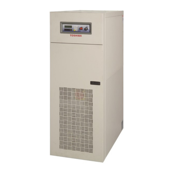
TOSHIBA 5.0 Specifications 4200FA 15 / 25 kVA @ 208 VAC Input/ 208 VAC Output w/Internal Batteries C42F3F150XAMBN C42F3F250XAMBN Model Number C42F3F150##MBN C42F3F250##MBN Rated Output Capacity 15 kVA 25 kVA External Dimensions 20.0” x 36.3” x 59.7” W x D x H (cm) (50.8 cm x 92.2 cm x 151.6 cm) -
Page 35: 4200Fa 15/25 Kva W/Internal Transformer
TOSHIBA 4200FA 15/25 kVA w/Internal Transformer Model Number C42#3*150#AMXN C42#3*250#AMXN # =(B: 208; H: 220; C: 240; N: 380–415 Δ-wye; P: 380–415 wye; D: 480; Input M: 600) VAC Output *=(F: 208; H: 220 wye; J: 240; P: 380–415 wye; K: 480 wye: M:600) VAC... -
Page 36: 4200Fa 30 Kva @ 208 Vac Input/ 208 Vac Output W/Internal Batteries
TOSHIBA 4200FA 30 kVA @ 208 VAC Input/ 208 VAC Output w/Internal Batteries T42F3F300XAMBN Model Number T42F3F300##MBN Rated Output Capacity 30 kVA External Dimensions 20.0” x 36.3” x 59.7” W x D x H (cm) (50.8 cm x 92.2 cm x 151.6 cm) -
Page 37: 4200Fa 30 Kva W/Internal Transformer
TOSHIBA 4200FA 30 kVA w/Internal Transformer Model Number T42#3*300#AMXN # =(B: 208; H: 220; C: 240; N: 380–415 Δ-wye; P: 380–415 wye; Input D: 480; M: 600) VAC *=(F: 208; H: 220 wye; J: 240; P: 380–415 wye; K: 480 wye:... -
Page 38: 4200Fa 50Kva @ 208 Vac Input/ 208 Vac Output W/Internal Batteries
TOSHIBA 4200FA 50kVA @ 208 VAC Input/ 208 VAC Output w/Internal Batteries T42F3F500XAMBN Model Number T42F3F500##MBN Rated Output Capacity 50 kVA External Dimensions 35.5” X 38.3” X 59.3” W x D x H (cm) (90.1 cm x 97.2 cm x 150.6 cm) -
Page 39: 4200Fa 50Kva W/Internal Transformer
TOSHIBA 4200FA 50kVA w/Internal Transformer Model Number T42#3*500#AMXN # =(B: 208; H: 220; C: 240; N: 380–415 Δ-wye; P: 380–415 wye; Input D: 480; M: 600) VAC *=(F: 208; H: 220 wye; J: 240; P: 380–415 wye; K: 480 wye;... -
Page 40: Operating The Ups
TOSHIBA 6.0 Operating the UPS AC Input Mode (Normal Operation) The following illustration shows circuit power flow when the UPS is operating normally in the AC Input Mode. The converter of the UPS, including a boost chopper circuit, converts the AC input power into DC power. -
Page 41: Bypass Mode
TOSHIBA Bypass Mode If the UPS unit is severely overloaded or develops an internal fault, power flow is automatically switched from the main circuit to the Bypass circuit. Power flow through the bypass is shown in the following illustration. This changeover occurs automatically in less than 4 milliseconds in phase (Make-Before-Break). -
Page 42: Battery Backup Mode
TOSHIBA Battery Backup Mode The following illustration shows power flow during the battery backup mode. When commercial AC power failures occur, the batteries instantly begin supplying DC voltage to the main inverter circuit. This circuit inverts (hence; Inverter) the DC power into AC po wer. -
Page 43: Battery Backup Time And Discharge Process
TOSHIBA Battery Backup Time and Discharge Process The UPS system, when used in conjunction with a TOSHIBA designed Battery System, is designed to provide several minutes of back-up time (Refer to the Battery System Manual for back-up times). These times are valid when the unit is operating under full load. When these models are operating at half load, the batteries can provide approximately 2 times the specified value. -
Page 44: Battery Recharging
TOSHIBA Battery Recharging The illustration below shows a graphical representation of the UPS battery recharge process after a full discharge. The recharge process usually consists of three steps. During the first step, the charging current is maintained at approximately 4.0 amperes for the 15/25/30 kVA with internal batteries, 10.0 amperes for the 15/25/30 kVA with internal transformer and approximately... -
Page 45: Front Panel Layout (All Units)
TOSHIBA Front Panel Layout (All Units) Refer to the following illustration for the entire UPS front panel operating procedures. 4-line liquid 4-line liquid Emergency Emergency crystal display crystal display Power Off switch STOP/RUN key power off switch STOP/RUN key screen (see... -
Page 46: Audible Alarm Functions
TOSHIBA 6.10 Audible Alarm Functions Audible alarms will sound when the UPS is in the Battery Backup Mode, has a fault, is at the low battery voltage, or is in an overload condition. The following chart shows the audible alarm pattern duration for each condition. Time intervals are shown in seconds. -
Page 47: Led (Light Emitting Diode) System Status
TOSHIBA 6.11.1 LED (Light Emitting Diode) System Status The following chart shows the UPS system status that can be determined by decoding the "on" and "off" condition of the LED lamps. It should be used in conjunction with the LCD display and the audible alarms for total system monitoring. -
Page 48: Line-2 System Fault Messages
TOSHIBA 6.12.2 Line-2 System Fault Messages Line-2 fault messages are automatically displayed when a system fault is detected. LINE-2 MESSAGES Display Message Translation DCOC DC Over-current DCUB DC Unbalanced DCOV DC Over-voltage Overheat (internal) Output Overload VOUV Inverter Under-voltage VOOV Inverter Over-voltage 6.12.3 Line-3 System Messages... -
Page 49: Initial Battery Charge
TOSHIBA Note: 1) Line-4 will be blank when the BATT key is pressed during Battery Backup Mode with normal battery voltage. 2) The # symbol signifies numerical values or other information supplied by the UPS. 6.13 Initial Battery Charge The UPS Battery System must be charged before it is used for the first time or when the unit has not been used (AC power source removed) for more than 10 days. -
Page 50: Start-Up Procedure
TOSHIBA 6.14 Start-up Procedure The UPS batteries must be charged before the UPS is used for the first time or if the unit has not been used (AC power source removed) for more than 10 days. If the batteries are charged then use the following start-up procedure: 1) Verify that all power switches are off, and that the "STOP/RUN”... -
Page 51: Shutdown Procedure
TOSHIBA 6.15 Shutdown Procedure When turning off the UPS, the following shutdown procedure should be used: Move the “STOP/RUN” key switch, located on the front panel, to “STOP." Operation of the inverter halts. Output power is now provided to the load through the unit's Bypass circuit. -
Page 52: Maintenance Bypass Procedure
TOSHIBA 6.16 Maintenance Bypass Procedure To safely set the unit in Maintenance Bypass, the UPS is first electrically switched to bypass mode, and then mechanically switched to bypass mode. This prevents the UPS from being placed in parallel with commercial power. -
Page 53: Keypad Overview
TOSHIBA 6.17 Keypad Overview The following illustrates the 12-key data entry pad with each key functionally labeled. MONI BATT BATT TEST BUZZ MENU ENTER STOP RESET Monitor – Press to display system-monitoring screens. MONI Battery – Press to display UPS battery conditions. -
Page 54: Key Functions
TOSHIBA 6.18 Key Functions 6.18.1 MONI After the UPS has been successfully started, the system will be in the normal 'AC Input Mode' of operation. The LCD screen will automatically display the main MONI (monitor) function. If the MONI key is pressed at this time the screen output will not change. The MONI function automatically monitors the entire UPS system. -
Page 55: Batt Key
TOSHIBA 6.18.4 BATT Key When the BATT key is pressed during normal 'AC Input Mode' of operation, the LCD screen displays details about the battery capacity. The following system message is displayed: - UPS ON-LINE - BATTERY VOLTAGE=324V CHARGE CURR.=0% If an AC input power failure occurs, and no abnormal operating conditions are present, the UPS will switch to standard 'Battery Backup Mode'. -
Page 56: Buzz Stop Key
TOSHIBA When the battery test is completed, the previous operation will be resumed and the main system MONI screen will be displayed. If the battery test detects a low DC battery voltage, then the message screen will display: - UPS ON-LINE -... -
Page 57: Menu Data Screens
TOSHIBA 6.19 Menu Data Screens 6.19.1 Settings for Calendar and Clock Press the MENU key to access the menu data screens and press the 'down' arrow key to scroll to the present date and time adjustment screen: CALENDER / CLOCK DATE (DAY) TIME >*F1: DATA SET MODE... -
Page 58: Run Switch Select
TOSHIBA DISPLAY DURATION SET <3 MIN> 30 MIN >Δ/∇: CHANGE DATA >ENTER:ACCEPT CHANGE Press the 'up' or 'down' arrow key to move the marker between the two available idle mode times. Press the ENTER key to save the change or press the MENU key to exit to the main menu and discard the change. -
Page 59: Output Voltage Adjustment
Pressing the F1 key will have no effect on this display screen 6.19.7 Equalize Charge Mode Select Contact Toshiba Customer Support toll free at 1-877-867-8773 before using this option. DAMAGE to the battery system may occur if this option is used improperly. -
Page 60: Reset To Default Settings
TOSHIBA 6.19.8 Reset to Default Settings Press the MENU key to access the menu data screens and press the 'down' arrow key to scroll to the original factory 'default settings' adjustment screen display: MENU DATA RESET DATA INITIALIZATION >F1: TO ACCESS RESET >Δ/∇:PRV/NEXT SCREEN... -
Page 61: Backup History And Fault History
TOSHIBA After the load is reduced, if the STOP/RUN key switch is in the RUN position, the UPS will automatically return to 'Inverter Operation’ after a period of time. During this wait, the following screen will be displayed: - BYPASS OPERATION -... - Page 62 TOSHIBA Press the F1 key again to display the record relating to each subsequent discharge event. BACKUP HISTORY ( #) #MIN##SEC VB=324V BT *PF OL >Δ/∇: EXIT F1: NEXT Press the ‘up’ or ‘down’ arrow keys to return to the Battery Discharge Count screen.
-
Page 63: Ups Protection System
TOSHIBA 7.0 UPS Protection System System Protection Features The preceding one-line schematic illustrates the electrical locations of the protection devices on all UPS models. Input Abnormal Overcurrent Overload Bypass MCCB Output Input Isolating Converter Inverter Power Power XFMR Overvoltage/ Charger/... -
Page 64: Start-Up/Scheduled Maintenance/Part Replacement
The best preventive measure that the UPS user can take is to keep the area around the unit, particularly the air inlet vents, clean and free of moisture and dust accumulations. Schedule authorized TOSHIBA service centers to perform an internal parts inspection semi-annually. -
Page 65: Parts Replacement
TOSHIBA Parts Replacement The following list shows intervals for periodic maintenance and replacement of certain UPS parts. 1) Batteries: VRLA (Valve Regulated Lead Acid) batteries do not require the adding of water or electrolyte. The charging voltage, temperature, performance and connection resistance must be monitored periodically. -
Page 66: External Dimensions / Shipping Dimensions / Weights
TOSHIBA 9.0 External Dimensions / Shipping Dimensions / Weights External Dimensions 15/25/30 kVA 15, 25, 30 kVA 36.3 in. (922 mm) 4200FA CT/XT User’s Manual... -
Page 67: External Dimensions 50Kva
TOSHIBA External Dimensions 50kVA 35.5 in. (901 mm) 59.3 in. (1506 mm) 38.3 in. (972 mm) 4200FA CT/XT User’s Manual... -
Page 68: Shipping Dimensions And Weights
TOSHIBA Shipping Dimensions and Weights Shipping Dimensions, Shipping Dimensions, All 15, 25 & 30 kVA models Standard with crate Inches (cm) Inches (cm) Width 42.8 (109) 43.5 (111) Depth 49.0 (125) 49.8 (127) Height 64.6 (164) 69.6 (177) Height with packing material 67.6 (172) - Page 70 INDUSTRIAL DIVISION 13131 West Little York Rd., Houston, TX 77041 Tel: 713/466-0277 Fax 713/466-8773 US 877/867-8773 Canada 800/872-2192 Mexico 01/800/527-1204 www.toshiba.com/ind Printed in the U.S.A.
Need help?
Do you have a question about the 4200 FA CT and is the answer not in the manual?
Questions and answers