Table of Contents
Advertisement
Available languages
Available languages
ÉQUIPEMENT DOYON INC.
1255, rue Principale
Linière, Qc, Canada G0M 1J0
Tel.: 1 (418) 685-3431
Canada: 1 (800) 463-1636
US: 1 (800) 463-4273
FAX: 1 (418) 685-3948
Internet:
http://www.doyon.qc.ca
e-mail:
doyon@doyon.qc.ca
JA6SLG - JA6SLSCG - JAOP6SLG - JA12SLG - JAOP12SLG
Product / Produit:
Serial number / Numéro de série:
Advertisement
Table of Contents

Subscribe to Our Youtube Channel
Related Manuals for Doyon JA6SLG


Summary of Contents for Doyon JA6SLG
- Page 1 Linière, Qc, Canada G0M 1J0 Tel.: 1 (418) 685-3431 Canada: 1 (800) 463-1636 US: 1 (800) 463-4273 FAX: 1 (418) 685-3948 Internet: http://www.doyon.qc.ca e-mail: doyon@doyon.qc.ca JA6SLG - JA6SLSCG - JAOP6SLG - JA12SLG - JAOP12SLG Product / Produit: Serial number / Numéro de série:...
-
Page 2: Table Of Contents
IMPORTANT SAFETY INSTRUCTIONS SAVE THESE INSTRUCTIONS DANGER TO REDUCE THE RISK OF FIRE OR ELECTRIC SHOCK CAREFULLY FOLLOW THESE INSTRUCTIONS TABLE OF CONTENTS (table des matières :page suivante) DESCRIPTION________________________________________________________________ A-1 Introduction________________________________________________________________ A-1 Construction _______________________________________________________________ A-1 Shipping __________________________________________________________________ A-1 Installation warnings_________________________________________________________ A-3 Distances to respect__________________________________________________________ A-4 Installation ________________________________________________________________ A-7 Operation of the oven _______________________________________________________ A-11... - Page 3 IMPORTANT INSTRUCTIONS DE SÉCURITÉ CONSERVEZ CE MANUEL D’INSTRUCTIONS DANGER AFIN DE RÉDUIRE LES RISQUES D'INCENDIE OU D'ÉLECTROCUTION SUIVRE CES INSTRUCTIONS AVEC SOIN TABLE DES MATIÈRES DESCRIPTION _________________________________________________________________A-2 Introduction ________________________________________________________________A-2 Construction ________________________________________________________________A-2 Expédition __________________________________________________________________A-2 Avertissement lors de l'installation_______________________________________________A-5 Distances à respecter _________________________________________________________A-6 Installation _________________________________________________________________A-9 Opération du four ___________________________________________________________A-12 Instructions pour four ________________________________________________________A-14...
-
Page 4: Description
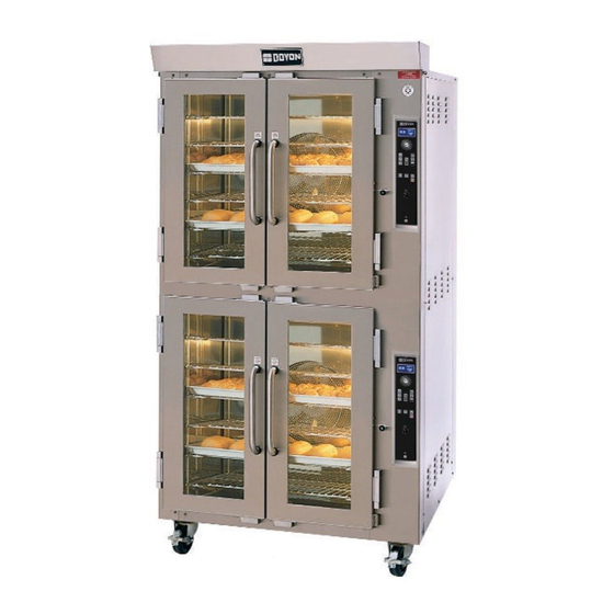
CONSTRUCTION You just bought the most advanced gas fired oven in the world, "DOYON" technology at its best. This gas fired oven is manufactured using the highest quality components and material. The oven gives a perfect uniform baking with its unique Jet Air convection system. The DOYON oven is designed with parts that are easy to find. -
Page 5: Introduction
CONSTRUCTION Vous avez maintenant en votre possession le four au gaz le plus performant présentement disponible sur le marché, un four utilisant la technologie "DOYON" à son meilleur. Ce four au gaz est fabriqué avec des matériaux de première qualité. -
Page 6: Installation Warnings
INSTALLATION WARNINGS The DOYON gas fired ovens are designed to be used with the gas specified on the descriptive nameplate. Refer to National Fuel Gas Code, ANSI-Z223.1 and CAN/CGA.B149. Refer to last edition year for XX. Copies of these are available at: American Gas Association, 1515 Wilson Boulevard, Arlington, Virginia, 22209. -
Page 7: Distances To Respect
DISTANCES TO RESPECT Back and sides of the oven: 1 inch. Top of the oven: a clearance of 12 inches to the ceiling must exist to permit adequate venting of the exhaust pipe and hot parts and to give proper access to a technician. The draft hood must have a clearance of 2 inches minimum all around. -
Page 8: Avertissement Lors De L'installation
AVERTISSEMENT LORS DE L'INSTALLATION Les unités au gaz "DOYON" sont fabriquées pour être utilisées uniquement avec le type de gaz spécifié sur la plaque d'identification. Se référer au Code National de Gaz, ANSI-Z223.1 et CAN/CGA.B149. Référez-vous à l’année de la dernière édition pour XX. Des copies de ces normes sont disponibles auprès de :... -
Page 9: Distances À Respecter
DISTANCES À RESPECTER Arrière et côtés du four : 1 pouce. Dessus du four : Il est obligatoire d'avoir au moins 12 pouces entre le dessus du four et le plafond de manière à permettre une ventilation adéquate du tuyau d'évacuation et des parties chauffantes tout en permettant l'accès à... -
Page 10: Installation
1. To the certified gas technician The burner installed on DOYON gas fired ovens is set up and adjusted at the plant for a first class operation. It is nevertheless necessary to verify on site the pressure at the burner input. The following table indicates the pressures that must be set up to remain conform to the AGA standards or CGA. - Page 11 Connect the steam system (1/4 NPT) to the cold water distribution network. We highly recommend a water softener to eliminate minerals in the water. We suggest you to use CUNO # CFS6135 (Doyon part number PLF240). WARNING Do not adjust the needle valves, it has been done at the factory.
-
Page 12: Installation
1. Au technicien spécialisé pour le gaz Le brûleur installé sur les fours au gaz DOYON est monté et ajusté à l'usine par le fabricant pour un fonctionnement optimal. Il est néanmoins nécessaire de vérifier sur place la pression à l'entrée du brûleur. - Page 13 Il est fortement recommandé d’installer un adoucisseur d’eau à l’entrée de l’appareil afin d’éliminer les minéraux dans l’eau. Nous recommandons la marque CUNO # CFS6135 (numéro de pièce DOYON PLF240). AVERTISSEMENT Ne jamais changer l'ajustement des valves à aiguille pré-ajustées.
-
Page 14: Operation Of The Oven
A-11 OPERATION OF THE OVEN 1. Turn the switch to the "1" position. • The light inside the oven must light up. 2. Adjust the thermostat at the desired setting (see THERMOSTAT INSTRUCTIONS below) N.B. The red light must be "ON" (If not, press the breaker on the front). 3. -
Page 15: Opération Du Four
A-12 OPÉRATION DU FOUR 1. Démarrer le four (tourner le sélecteur à la position ‘’1’’). • La lumière à l'intérieur du four doit allumer. 2. Ajuster le thermostat à la température désirée (voir FONCTIONNEMENT DU THERMOSTAT) N.B. L'affichage digital doit être allumé. Si ce n'est pas le cas, vérifier le disjoncteur situé sur le panneau avant. -
Page 16: Instructions For Oven
A-13 INSTRUCTIONS FOR OVEN OPENING AND CLOSING THE DOORS To open the doors: Open one of the doors up to 2" and wait 2 seconds to let the fan reduce its spinning before opening them completely. To close the doors: Close the first door completely and the second door down to 2"... -
Page 17: Instructions Pour Four
A-14 INSTRUCTIONS POUR FOUR OUVERTURE ET FERMETURE DES PORTES Pour ouvrir les portes: Ouvrir une des portes de 2 pouces et attendre 2 secondes afin de permettre au ventilateur de diminuer sa vitesse avant d’ouvrir complètement. Pour fermer les portes : Fermer la première porte complètement et la deuxième jusqu'à 2 pouces et attendre 2 secondes avant de fermer ensuite maintenir fermer 2 secondes. -
Page 18: Operation Of The Proofer
A-15 OPERATION OF THE PROOFER 1. Switch "ON" (1). 2. Set the thermostat control at 100° F. 3. Set the humidity control at approximately: 3 for JAOP-3 & JAOP-6 4 or 5 for JAOP-10 5 for JAOP-14 4. If there is too much fog and water drips from the glass doors, adjust humidity control to a lower number. -
Page 19: Opération De L'étuve
A-16 OPÉRATION DE L'ÉTUVE 1. Placer l'interrupteur à "ON" (1). ° 2. Placer le bouton du thermostat à 100 3. Placer le bouton d'humidité à approximativement : 3 pour JAOP-3 & JAOP-6 4 ou 5 pour JAOP-10 5 pour JAOP-14 4. -
Page 20: Ecm-1 Programmable Control - Operating Modes
A-17 ECM-1 PROGRAMMABLE CONTROL - OPERATING MODES The Doyon ECM-1 controller has two operation modes Manual and Programmable. MANUAL: to use all functions without using recipe program. PROGRAMMABLE: to use with recipe cook program. Program capacity □ Programs #1 to #99 can have up to 10 steps each (low-level programmable). - Page 21 A-18 How to select a cook program or the Manual Mode To select a recipe program, enter the recipe number with the numeric keypad and press (Start) or use the Next or Previous arrow to jump from one to an other program without having to confirm with the (Start) key.
-
Page 22: Manual Mode
A-19 MANUAL MODE This mode is used to work one step program. Press on (Start) when the oven is ON, the oven will run on preheat mode at the manual mode set point (by exception if you select a cook program referred in the PROGRAM MODE section). TEMPERATURE FUNCTION To change the temperature set point, press and hold for 3 sec. -
Page 23: Program Mode
A-20 PROGRAM MODE This mode is used to program a Cook Recipe. Cook Program structure A cook program consists of a name as well as a number of steps. The name is pre-programmed into the unit (each name can have up to 30 characters). Each step has the following programmable parameters: Oven temperature: the oven set point for this step. - Page 24 A-21 Steam □ 1 parameter can be: OFF, ON, PULSE. ○ If OFF, steam remains off for duration of step. ○ If ON, steam remains on for duration of step. ○ If PULSE, pulsed steam is enabled for duration of step. □...
- Page 25 A-22 When a Cook Program is used, if the timer is inactive, the oven is considered idle COOK MODE (but it still maintains the set point). In Manual Mode, the timer is used only as a reminder, this mode can cook without using the timer. Display/LED □...
- Page 26 A-23 SYSTEM DIAGNOSTICS Cavity Probe Alarm □ Occurs when units detects a defective cavity or food temperature probe. □ Unit goes into Off mode with error message CAVITY PROBE ERROR or FOOD PROBE ERROR. Accessory Failure □ Occurs when input signal is no longer received. □...
-
Page 27: Contrôle Programmable Ecm-1 - Modes D'opération
A-24 CONTRÔLE PROGRAMMABLE ECM-1 - MODES D'OPÉRATION Le contrôleur ECM-1 Doyon est doté du mode de fonctionnement manuel et programmable. MANUEL : pour l’utilisation des fonctions sans avoir de recettes à programmer. PROGRAMMABLE : ce mode est utilisé pour programmer une recette de cuisson. - Page 28 A-25 Comment sélectionner une recette programmée ou le Mode Manuel Pour choisir une recette programmée, entrez le numéro de la recette à l'aide du clavier numérique et appuyez sur (départ ou utilisez les flèches pour sauter d'un programme à l'autre sans avoir à...
-
Page 29: Mode Manuel
A-26 MODE MANUEL Ce mode est employé pour l’utilisation des fonctions sans avoir de recettes à programmer. FONCTION TEMPÉRATURE Pour changer le degré de température désiré, appuyez 3 sec. sur . Lorsque apparaît à gauche de l'affichage, appuyez sur (haut / bas) pour choisir le degré de température désiré. La nouvelle consigne devrait s’enregistrer automatiquement après 3 secondes. -
Page 30: Mode Programmable
A-27 MODE PROGRAMMABLE Ce mode est utilisé pour programmer une recette de cuisson. Structure d'un Programme de Cuisson Un Programme de Cuisson consiste donc en un nom de recette qui est préenregistré dans le contrôle (chaque nom peut contenir jusqu'à 30 caractères, PC requis). Les paramètres suivants peuvent être programmés pour chacune des étapes d'une recette : Température four : point de consigne du four pour cette étape. - Page 31 A-28 Vapeur □ Pour le 1 paramètre, les choix sont : MARCHE, ARRET, PULSE. ○ ARRET : la vapeur reste fermée pour toute la durée de l'étape. ○ MARCHE : la vapeur reste active pour toute la durée de l'étape. ○...
- Page 32 A-29 Fonction par défaut lors de l'utilisation d'un Programme de Cuisson (ou Mode MODE CUISSON Manuel). Si la minuterie n'est pas active, le four est considéré inactif (mais le point de consigne est maintenu). Affichage/DEL ère □ L'affichage sur la 1 ligne de l'écran dépend du type d'affichage sélectionné: ○...
- Page 33 A-30 DIAGNOSTIQUE DU SYSTÈME Alarme de sonde de cavité □ Survient lorsque l'unité détecte une défectuosité en ce qui concerne la sonde de cavité ou la sonde de nourriture. □ L'unité se met en mode Arrêt et affiche le message ERREUR DE SONDE DE CAVITE ou message ERREUR DE SONDE DE NOURRITURE Défectuosité...
-
Page 34: Ecm-2 Programmable Control - Operating Modes
A-31 ECM-2 PROGRAMMABLE CONTROL - OPERATING MODES 1. Turn the main switch "ON" (1). 2. The light inside the proofer will turn ON and the digital control will indicate a code. Then, "PREH" will flash. 3. "PREH" will be displayed on the control until it reaches the set temperature. 4. -
Page 35: Contrôle Programmable Ecm-2 - Modes D'opération
A-32 CONTRÔLE PROGRAMMABLE ECM-2 - MODES D'OPÉRATION 1. Placer l'interrupteur à "ON" (1). 2. La lumière à l’intérieur de l’étuve s’allumera et le contrôle digital affichera un code. Ensuite," PREH " clignotera. 3. Le contrôle affichera " PREH " jusqu’à ce que l’étuve atteigne les paramètres d’étuvage demandés. -
Page 36: Troubleshooting
A-33 TROUBLESHOOTING BEFORE CALLING FOR SERVICE ANSWERS TO MOST FREQUENT QUESTIONS Always cut off the main power before replacing any parts. Take care of water and electric wire supply system when pulling the oven. Control parts on the front and proofer Remove the side panels of the oven and the control: proofer by screwing out the screws. - Page 37 A-34 Uneven baking. Make sure that the grills do not obstruct the air flow. Do not use foil on the grills. Verify the temperature of the oven by using an oven thermometer and make sure that it is even with the thermostat setting. If the oven is baking too much on the sides, it is possible that the fan is not cycling properly.
-
Page 38: Dépannage
A-35 DÉPANNAGE AVANT D'APPELER LE DÉPARTEMENT DE SERVICE SOLUTION AUX PROBLÈMES LES PLUS FRÉQUENTS Toujours fermer l'approvisionnement du courant principal avant le remplacement de pièces. Prendre garde aux tuyaux de gaz et d'eau avant de déplacer le four. Les pièces de contrôle du four et de l'étuve: Enlever le panneau de contrôle avant (dévisser les vis du panneau et le basculer lentement vers l'avant). - Page 39 A-36 Cuisson inégale. Assurez-vous que les grilles permettent à l'air de circuler librement. Ne recouvrez pas les grilles de papier d'aluminium. Vérifiez la température du four à l'aide d’un thermomètre à four et comparez avec le réglage du thermostat. Si le four cuit trop au fond ou sur les côtés, le temps de fonctionnement des ventilateurs peut être déréglé.
-
Page 40: Oven Maintenance And Cleaning
A-37 OVEN MAINTENANCE AND CLEANING MAINTENANCE OF THE BURNER • Once a year, you should ask a certified technician to make a tune up. Make sure everything works properly, verify and clean especially: 1. The gas mixer air inlet. 2. The spark rod and porcelain insulators. 3. -
Page 41: Entretien Et Nettoyage Du Four
A-38 ENTRETIEN ET NETTOYAGE DU FOUR ENTRETIEN DU BRÛLEUR • Vous devriez faire faire l'entretien de votre système de brûleur par un technicien qualifié une fois par année. Le technicien doit s'assurer que tout fonctionne bien, vérifier et nettoyer spécialement: 1. -
Page 42: Bake Chart
A-39 BAKE CHART BAKERY OVENS (Table as reference only) Bake Time Bake Temp Bake Temp Menu item Minutes ºF ºC Bagels (16 per pan) Dinner rolls (16 per pan) 15-18 Sub rolls 12" (10 per pan) 15-18 French Baguette (5 per pan) 20-25 Croissants (15 per pan) 12-15... -
Page 43: Tableau De Cuisson
A-40 TABLEAU DE CUISSON FOURS À PAIN ET PÂTISSERIE (Tableau à titre de référence seulement) Temps Temp. Temp. Item cuisson min. cuisson ºF cuisson ºC Bagels (16 par plaque) Pain à salade (16 par plaque) 15-18 Sous-marin 12" (10 par plaque) 15-18 Baguettes (5 par plaque) 20-25... -
Page 44: Component Parts
SECTION B: COMPONENT PARTS PIÈCES COMPOSANTE JAOP12SLG – FRONT VIEW JAOP12SLG – VUE DE FACE... - Page 45 Item Part # Description Quant PAR800 SWIVEL CASTER ROULETTE PIVOTANTE PAR850 SWIVEL CASTER WITH BRAKE ROULETTE PIVOTANTE AVEC FREIN QUP320 DOOR HINGE PENTURE DE PORTE QUP520 MAGNETIC HANDLE POIGNÉE MAGNÉTIQUE ELB097 20A BREAKER DISJONCTEUR 20A ELB096 5A BREAKER DISJONCTEUR 5A ELI402 BLACK SELECTOR 2 POS.
-
Page 46: Jaop12Slg - Right Side View
JAOP12SLG – RIGHT SIDE VIEW JAOP12SLG – VUE DE CÔTÉ DROIT... - Page 47 Item Part Number Description Quantity ELM760 COOLING FAN 120V ELM570 DOOR SWITCH 15A ELS950 BUZZER 120V ELT503 HIGH LIMIT SWITCH 140°F ELD081 FRAME AND LIGHT SOCKET 77-708 120 VOLT ELD082 FRAME AND LIGHT SOCKET 77-708 230 VOLT 50010894 ASSY. FRAME,CLASS,GASKET AND SCREW FOR ELD081 & ELD082 Item Num.
-
Page 48: Jaop12Slg - Left Side View
JAOP12SLG – LEFT SIDE VIEW JAOP12SLG – VUE DE CÔTÉ GAUCHE... - Page 49 Item Part Number Description Quantity ELC860 CONTACTOR 2P 30A 110V ELC615 RELAY 10A 2P COIL 110V ELC617 BASE ELC630 CONTROL RELAY 12A COIL 120V ELC640 CONTROL RELAY BASE ELM730 PROOFER FAN BLOWER ELT505 HIGH LIMIT TEMPERATURE 300°F ELD050 INCANDESCENT LIGHT SOCKET ELA275 BULB 60W 130V QUF350...
-
Page 50: Jaop12Slg - Back View
JAOP12SLG – BACK VIEW JAOP12SLG – VUE ARRIÈRE... - Page 51 Item Part Number Description Quantity GAP300 PRESSURE SWITCH DWYER ELT705 TRANSFORMER 120/240V TO 12/24V 100VA. GAB500 ELECTRONIC CONTROL ( HONEYWELL S87D ) GAD200 FLAME DETECTION ROD GAD190 IGNITION ROD GAM200 ATMOSPHERIC MIXER GAC230 HONEYWELL GAS VALVE #VR8205A2800 GAC241N NATURAL GAS PRESSURE REGULATOR GAC241P PROPANE GAS PRESSURE REGULATOR PLF100...
-
Page 52: Control Panels
SECTION C: CONTROL PANELS PANNEAUX DE CONTRÔLE 1PH 120V WITH ZELIO 1PH 120V AVEC ZELIO... -
Page 53: 1Ph 120V Without Zelio
1PH 120V WITHOUT ZELIO 1PH 120V SANS ZELIO... -
Page 54: 120/208-240V 1Ph With Zelio Simple
120/208-240V 1PH WITH ZELIO SIMPLE 120/208-240V AVEC ZELIO SIMPLE... -
Page 55: 120/208-240V Without Zelio Simple
120/208-240V WITHOUT ZELIO SIMPLE 120/208-240V SANS ZELIO SIMPLE... -
Page 56: Burner Adjustements
SECTION D: BURNER ADJUSTEMENTS AJUSTEMENT DU BRÛLEUR NATURAL GAS GAZ NATUREL... -
Page 57: Propane Gas
PROPANE GAS GAZ PROPANE... -
Page 59: Limited Warranty
Doyon Equipment Inc. does hereby exclude and shall not be liable to purchaser for any consequential or incidental damages including, but not limited to, damages to property, damages for loss of use, loss of time, loss of profits or income, resulting from any breach or warranty. - Page 60 L'étendue des obligations du manufacturier, selon cette garantie, est le remplacement ou la réparation des pièces défectueuses durant la période de garantie. L'acceptation de la garantie sera faite par le département de service d'Équipement Doyon Inc. Cette décision sera définitive.
Need help?
Do you have a question about the JA6SLG and is the answer not in the manual?
Questions and answers