Table of Contents
Advertisement
Quick Links
Advertisement
Table of Contents

Related Manuals for Moxa Technologies CSM-200-1213


Summary of Contents for Moxa Technologies CSM-200-1213
- Page 1 CSM-200 Series Hardware Installation Guide First Edition, November 2009 © 2009 Moxa Inc. All rights reserved. Reproduction without permission is prohibited. Fl.4, No.135, Lane 235, Pao-Chiao Rd. Shing Tien City, Taipei, Taiwan, R.O.C. TEL: +886-2-8919-1230 P/N: 1802002002010...
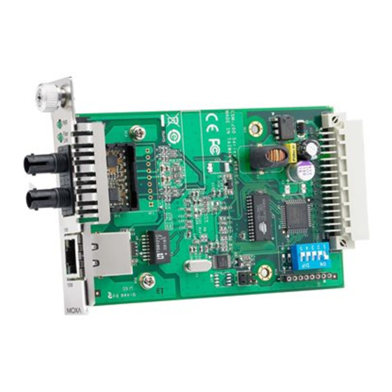
- Page 2 BaseT(X) to 100 BaseFX (SC or ST connectors), and can be installed in every chassis of the NRack System. The CSM-200 Series includes the following models: • CSM-200-1213: 10/100BaseT(X) to 100BaseFX slide-in module media converter, multi-mode ST connector. • CSM-200-1214: 10/100BaseT(X) to 100BaseFX slide-in module media converter, multi-mode SC connector.
-
Page 3: Package Checklist
CSM-200 Series Hardware Installation Guide Warranty Card NOTE: Please notify your sales representative if any of the above items are missing or damaged. Dimensions CSM-200-1213 Fiber Link 86.8 mm (3.42 in) 100M 117.1 mm (4.61 in) 124.3 mm (4.89 in) 21 mm (0.83 in) -
Page 4: Communication Connections
CSM-200-1214/CSM-200-1218 Fiber Link 86.8 mm (3.42 in) 100M 117.1 mm (4.61 in) 124.3 mm (4.89 in) 21 mm (0.83 in) ATTENTION Electrostatic Discharge Warning! To protect the product from damage due to electrostatic discharge, we recommend wearing a grounding device when handling your CSM-200 slide-in modules. - Page 5 RJ45 (8-pin) to RJ45 (8-pin) Straight-Through Cable Wiring Straight-Through Cable Switch Port NIC Port RJ45 Plug Pin 1 RJ45 RJ45 Connector Cable Wiring Connector RJ45 (8-pin) to RJ45 (8-pin) Cross-Over Cable Wiring Switch Port Cross-Over Cable Switch Port (NIC Port) (NIC Port) RJ45 Plug Pin 1 RJ45...
-
Page 6: Switch Settings
ATTENTION This is a Class 1 Laser/LED product. Do not stare into the Laser Beam. Switch Settings There is 1 set of DIP switches on the board. The following figure and table give the settings for the 5-connector DIP switch. Function Auto Negotiation Enable... -
Page 7: Auto Mdi/Mdi-X Connection
Auto MDI/MDI-X Connection The Auto MDI/MDI-X function allows users to connect the Moxa CSM-200’s 10/100BaseTX ports to any kind of Ethernet device, without needing to determine the type of Ethernet cable being used for the connection. This means that you can use either a straight-through cable or cross-over cable to connect the CSM-200 Series to Ethernet devices. -
Page 8: Specifications
Specifications Technology Standards IEEE 802.3 for 10BaseT, IEEE 802.3u for 100BaseT(X), 100BaseFX Interface RJ45 ports 10/100BaseT(X) Fiber ports 100BaseFX (SC/ST connector) LED Indicators PWR, Fiber Link, 10/100M(TP port) Optical Fiber 100BaseFX Multi-mode Single-mode Wavelength 1300 nm 1310 nm Max. TX -10 dBm 0 dBm Min. - Page 9 EN61000-4-2 (ESD), Criteria A, Level 4 EN61000-4-3 (RS), Criteria A, Level 2 EN61000-4-4 (EFT), Criteria A, Level 3 EN61000-4-5 (Surge), Criteria A, Level 3 EN61000-4-6 (CS), Criteria A, Level 2 En61000-4-8 (PFMF), Criteria A, Level 3 Freefall IEC 60068-2-32 Warranty Warranty Period 5 years Details: See www.moxa.com/warranty...
Need help?
Do you have a question about the CSM-200-1213 and is the answer not in the manual?
Questions and answers