Table of Contents
Advertisement
Advertisement
Table of Contents

Related Manuals for Crestron Isys TPS-6L


Summary of Contents for Crestron Isys TPS-6L
- Page 1 Crestron TPS-6L Isys 5.7” Wall Mount Touchpanel ® Operations & Installation Guide...
- Page 2 This document was prepared and written by the Technical Documentation department at: Crestron Electronics, Inc. 15 Volvo Drive Rockleigh, NJ 07647 1-888-CRESTRON All brand names, product names and trademarks are the property of their respective owners. ©2008 Crestron Electronics, Inc.
-
Page 3: Table Of Contents
® Crestron TPS-6L Isys 5.7” Wall Mount Touchpanel Contents ® Isys 5.7” Wall Mount Touchpanel: TPS-6L Introduction ......................1 Features and Functions................1 Applications ...................3 Internal Block Diagram................4 Specifications ..................4 Physical Description................7 Industry Compliance ................11 Setup........................12 Network Wiring ...................12 Identity Code..................12 Configuring the Touchpanel..............13 Mounting Options ................29... -
Page 5: Isys 5.7" Wall Mount Touchpanel: Tps-6L
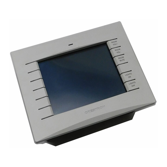
Featuring a bright, beautiful, high- contrast 5.7" color touchscreen with 16-bit Isys graphics, 640 x 480 resolution and single video window display, the TPS-6L delivers a world of control capability yet leaves a very small footprint. The addition of 12 optional pushbuttons provides quick access to commonly used functions. - Page 6 Crestron Home CAT5 AV The TPS-6L is ideal for use with AV distribution and intercom systems of all sizes. Its balanced audio and video connections make installation easy and affordable using inexpensive CAT5 type wire and Crestron's popular CH CAT5 Balanced AV distribution switchers.
-
Page 7: Applications
Versatile Flush Mount Design The TPS-6L is designed for easy flush mount installation in a wall, lectern or similar flat surface. Mounting clips furnished with the TPS-6L facilitate a clean installation in drywall and many furniture applications. Additional mounting options are available separately including optional back box and 19”... -
Page 8: Internal Block Diagram
® Isys 5.7” Wall Mount Touchpanel Crestron TPS-6L Internal Block Diagram The following diagram represents the basic operation of the TPS-6L. TPS-6L Internal Block Diagram Specifications Specifications for the TPS-6L are listed in the following table. TPS-6L Specifications SPECIFICATION DETAILS... - Page 9 System Update File Environmental Temperature 32º to 104ºF (0º to 40ºC) Humidity 10% to 90% RH (non-condensing) Heat Dissipation 51 BTU/Hr (Continued on following page) ® 5.7” Wall Mount Touchpanel: TPS-6L • 5 Operations & Installation Guide – DOC. 6630A Isys...
- Page 10 Crestron Home CAT5 Balanced AV Cable 1. The panel will not load dynamic graphics if they are located on a password protected HTTP server. 2. The latest software versions can be obtained from the Crestron website. Refer to the NOTE following these footnotes.
-
Page 11: Physical Description
Isys 5.7” Wall Mount Touchpanel Crestron 2-Series control systems include the AV2 and PRO2. Consult the latest Crestron Product Catalog for a complete list of 2-Series control systems. NOTE: Crestron software and any files on the website are for Authorized Crestron dealers and Crestron Authorized Independent Programmers (CAIP) only. - Page 12 ® Isys 5.7” Wall Mount Touchpanel Crestron TPS-6L TPS-6L Dimensions – Front and Side View with Cutaway Showing Internal Controls TPS-6L Dimensions and Connections – Rear View ® 8 • Isys 5.7” Wall Mount Touchpanel: TPS-6L Operations & Installation Guide - DOC. 6630A...
- Page 13 Maximum input level: 2 V balanced/unbalanced; Normally connects to a Crestron CAT5 balanced audio source via CresCAT cable Maximum CAT5 cable length: 1000 feet (Continued on following page) ® 5.7” Wall Mount Touchpanel: TPS-6L • 9 Operations & Installation Guide – DOC. 6630A Isys...
- Page 14 3. For details on CAT5 wiring, refer to the latest version of the CAT5 Reference Guide (Doc. 6137), which is available for download from the Crestron website (www.crestron.com/manuals). CAUTION: Do not attempt to press the reset button by inserting a paperclip or similar device through the small hole in the bezel.
-
Page 15: Industry Compliance
Isys 5.7” Wall Mount Touchpanel Industry Compliance As of the date of manufacture, the TPS-6L has been tested and found to comply with specifications for CE marking and standards per EMC and Radiocommunications Compliance Labelling. NOTE: This device complies with part 15 of the FCC rules. Operation is subject to... -
Page 16: Setup
Identity Code Net ID The Net ID of the TPS-6L has been factory set to 03. The Net IDs of multiple TPS-6L devices in the same system must be unique. The Net ID is set using the internal setup menu (refer to “Interface Menu” which starts on page 15). The Net ID may also be set from a personal computer (PC) via the Crestron Toolbox™... -
Page 17: Configuring The Touchpanel
Program, Setup and Diagnostics. After all setup procedures are completed, press Exit and Run Program to save the information to EEPROM and exit Setup Mode. ® 5.7” Wall Mount Touchpanel: TPS-6L • 13 Operations & Installation Guide – DOC. 6630A Isys... -
Page 18: Calibration Menu
Another message, “Touch Upper Right”, appears with a cross hair in the correct corner. Touch the center of the cross ® 14 • Isys 5.7” Wall Mount Touchpanel: TPS-6L Operations & Installation Guide - DOC. 6630A... -
Page 19: Setup Menu
The touchpanel communicates with a control system to activate commands or to display feedback from components within the system. The communication interface must be correctly specified or communication will not occur. To set communication ® 5.7” Wall Mount Touchpanel: TPS-6L • 15 Operations & Installation Guide – DOC. 6630A Isys... - Page 20 Windows program of the Cresnet system. Matching IDs between touchpanel and SIMPL Windows program is required if data is to be successfully transferred. The Net ID for the TPS-6L is factory set to 03. No two devices in the same system can have the same Net ID.
- Page 21 Use the + and – buttons to adjust the setting of the CTP port. To select the default port, press the Set Default Port button. ® 5.7” Wall Mount Touchpanel: TPS-6L • 17 Operations & Installation Guide – DOC. 6630A Isys...
- Page 22 IP address, the subnet mask, and the default router address. Each EDIT button selection displays a submenu similar to the following: EDIT IP ADDRESS Submenu • Press Return to go back to the ETHERNET MENU. ® 18 • Isys 5.7” Wall Mount Touchpanel: TPS-6L Operations & Installation Guide - DOC. 6630A...
- Page 23 DNS addresses, and the primary and secondary WINS addresses. Each EDIT submenu is similar to the following: EDIT PRIMARY DNS Submenu • Press Return to go back to the ETHERNET MENU. ® 5.7” Wall Mount Touchpanel: TPS-6L • 19 Operations & Installation Guide – DOC. 6630A Isys...
- Page 24 Pressing Audio Line In displays the following menu screen which is used to set levels for the speaker option, SPK-6L, if installed. AUDIO SETUP Menu – Audio Line In ® 20 • Isys 5.7” Wall Mount Touchpanel: TPS-6L Operations & Installation Guide - DOC. 6630A...
- Page 25 Press Hide Controls to remove the controls from the display. The button legend changes to Show Controls to let you display them for further adjustment. ® 5.7” Wall Mount Touchpanel: TPS-6L • 21 Operations & Installation Guide – DOC. 6630A Isys...
- Page 26 SCREEN SETTINGS Menu • With Auto Brightness Control set to OFF (default), the screen brightness is at the level set by the screen brightness controls. ® 22 • Isys 5.7” Wall Mount Touchpanel: TPS-6L Operations & Installation Guide - DOC. 6630A...
- Page 27 Backlit Engraving Settings From the SETUP MENU screen, press Backlit Engraving Settings to display the BACKLIT ENGRAVING SETTINGS menu as shown below. BACKLIT ENGRAVING SETTINGS Menu ® 5.7” Wall Mount Touchpanel: TPS-6L • 23 Operations & Installation Guide – DOC. 6630A Isys...
- Page 28 Advanced Options From the SETUP MENU screen, press Advanced Options to display the ADVANCED OPTIONS MENU as shown below. ADVANCED OPTIONS MENU ® 24 • Isys 5.7” Wall Mount Touchpanel: TPS-6L Operations & Installation Guide - DOC. 6630A...
- Page 29 When the sensor is below the threshold, the key backlight brightness is set to the high level. When the sensor is above the threshold, the key backlight brightness is set to the low level. ® 5.7” Wall Mount Touchpanel: TPS-6L • 25 Operations & Installation Guide – DOC. 6630A Isys...
- Page 30 Use the High-, Medium-, and Low Brightness Level controls to adjust the preset levels as desired. Key Backlight Settings Select Key Backlight Settings to display the KEY BACKLIGHT menu as shown on the following page. ® 26 • Isys 5.7” Wall Mount Touchpanel: TPS-6L Operations & Installation Guide - DOC. 6630A...
- Page 31 Use the High-, Medium-, and Low Backlight Level controls to adjust the preset levels as desired. Graphics Options Select Graphics Options to display the GRAPHICS MENU as follows. ® 5.7” Wall Mount Touchpanel: TPS-6L • 27 Operations & Installation Guide – DOC. 6630A Isys...
- Page 32 Diagnostics The Diagnostics button from the MAIN MENU should only be used under supervision from a Crestron customer service representative during telephone support. Many options available from the DIAGNOSTICS MENU, shown on the following page, are numeric in nature and their interpretation is beyond the scope of this manual.
-
Page 33: Mounting Options
The TPS-6L touchpanel installs simply and cleanly into existing or newly constructed walls, with an assortment of pre- and post-construction mounting options. The TPS-6L is supplied with four screws and clips for post-construction installation. All available mounting options are listed in the following table. The options listed are provided separately from the actual touchpanel. -
Page 34: Touchpanel Mounting
NOTE: Pre-construction refers to framed walls prior to hanging drywall. Post-construction refers to framed walls with drywall hung. NOTE: There is also a rack mount kit (RMK-6L) available for the TPS-6L. Refer to the latest version of the RMK-6L Installation Guide (Doc. 6599). - Page 35 ® Crestron TPS-6L Isys 5.7” Wall Mount Touchpanel TPS-6L Cutout Dimensions (4504078, 1 of 2) 6 5/8 in 5/16 in (169 mm) (8 mm) TEMPLATE - DV40090 FOR TPS-6L MOUNTING CLIPS ONLY 1 OF 2 DO NOT USE FOR BB-6L, PMK-6L, TMK-6L, MMK-6L, WMKM-6L, WMKT-6L...
- Page 36 4. Remove the template, and then cut out and remove the traced shape to produce the required opening. NOTE: Before inserting the TPS-6L in the mounting hole, ensure that all required cables have been installed in the wall. 5. Install the four supplied #6 x 2-½” screws and mounting clips as shown in the following diagram (two on the top and two on the bottom).
- Page 37 Use the Crestron Engraver software package to obtain a custom-engraved bezel for the TPS-6L. Install the bezel as follows. 1. Carefully position the bezel over the face of the touchpanel. 2. Ensure that the bezel is oriented properly and press against the TPS-6L until the bezel snaps into place. ®...
-
Page 38: Touchpanel Removal
Hardware Hookup Ventilation The TPS-6L should be used in a well-ventilated area. The venting holes should not be obstructed under any circumstances. If the TPS-6L is hot to the touch, consider used forced air ventilation. To prevent overheating, do not operate this product in an area that exceeds the environmental temperature range listed in the table of specifications. -
Page 39: Recommended Cleaning
CAUTION: Do not apply excessive pressure to the touchscreen display during handling. Doing so can crack the screen and damage the touchpanel. NOTE: The TPS-6L can only be powered via the 4-position terminal block connector labeled NET. Power cannot be supplied from network devices that are connected to the mini-terminal block connectors. -
Page 40: Programming Software
Have a question or comment about Crestron software? Answers to frequently asked questions (FAQs) can be viewed in the Online Help section of the Crestron website. To post a question or view questions you have submitted to Crestron’s True Blue Support, log in at http://support.crestron.com. - Page 41 Device Library. • To incorporate the TPS-6L into the system, drag the TPS-6L from the Touchpanels | Touchpanels (Cresnet) folder (or the Touchpanels (Ethernet) folder) of the Device Library and drop it in the System Views.
- Page 42 5.7” Wall Mount Touchpanel Crestron TPS-6L • Additional TPS-6L devices are assigned different Net ID (for Cresnet devices) or IP ID (for Ethernet devices) numbers as they are added. • If necessary, double click a device to open the “Device Settings” window and change the Net ID or IP ID, as shown in the following figures.
-
Page 43: Programming With Visiontools Pro-E
Touchpanel screens should be created in VisionTools Pro-e to allow switching of source signals to desired outputs as well as selection of the system mode. There are no special programming requirements to use the functions of the TPS-6L in a room- control system. - Page 44 This conversion to a 16-bit image may cause the loss of some subtle shading. To compensate for this, use the dithering to simulate the original shading. Various dithering types are available. Refer to the following illustrations. ® 40 • Isys 5.7” Wall Mount Touchpanel: TPS-6L Operations & Installation Guide - DOC. 6630A...
-
Page 45: Multibyte International Characters
Multibyte character fonts require more than the usual eight bits to specify a character. This occurs when a language has more than 256 characters (2 ) in a font. ® 5.7” Wall Mount Touchpanel: TPS-6L • 41 Operations & Installation Guide – DOC. 6630A Isys... -
Page 46: Example Program
Windows XP is available in many international languages and add-on software is available for other versions of Windows. Example Program An example program for the TPS-6L is available from the Crestron website (www.crestron.com/exampleprograms). ® 42 • Isys 5.7”... -
Page 47: Uploading And Upgrading
Use the Address Book in Crestron Toolbox to create an entry for the TPS-6L using the expected communication protocol (Indirect). Select the Cresnet ID of the TPS-6L and the address book entry of the control system that is connected to the TPS-6L. -
Page 48: Programs, Projects And Firmware
• Select Functions | IP Table Setup. • Add, modify or delete entries in the IP table. The TPS-6L can have only one IP table entry. • A defined IP table can be saved to a file or sent to the device. -
Page 49: Problem Solving
® Crestron TPS-6L Isys 5.7” Wall Mount Touchpanel Problem Solving Troubleshooting The following table provides corrective action for possible trouble situations. If further assistance is required, please contact a Crestron customer service representative. TPS-6L Troubleshooting TROUBLE POSSIBLE CORRECTIVE ACTION CAUSE(S) TPS-6L not Net ID is not correct. -
Page 50: Check Network Wiring
Cresnet power usage of the entire chain. If the unit is home-run from a Crestron system power supply network port, the Cresnet power usage of that unit is the Cresnet power usage of the entire run. The wire gauge and the Cresnet power usage of the run should be used in the following equation to calculate the cable length value on the equation’s left side. -
Page 51: Reference Documents
Crestron's award winning customer service team by calling Crestron at 1-888-CRESTRON [1-888-273-7876]. You can also log onto the online help section of the Crestron website (www.crestron.com/onlinehelp) to ask questions about Crestron products. First-time users will need to establish a user account to fully benefit from all available features. -
Page 52: Software License Agreement
Agreement, which shall remain valid and enforceable according to its terms. This Agreement may only be modified by a writing signed by an authorized officer of Crestron. Updates may be licensed to You by Crestron with additional or different terms. This is the entire agreement between Crestron and You relating to the Software and it supersedes any prior representations, discussions, undertakings, communications or advertising relating to the Software. - Page 53 “applets” incorporated into the Software), the accompanying media and printed materials and any copies of the Software are owned by Crestron or its suppliers. The Software is protected by copyright laws and international treaty provisions. Therefore, you must treat the Software like any other copyrighted material, subject to the provisions of this Agreement.
-
Page 54: Return And Warranty Policies
Purchasers should inquire of the dealer regarding the nature and extent of the dealer's warranty, if any. CRESTRON shall not be liable to honor the terms of this warranty if the product has been used in any application other than that for which it was intended or if it has been subjected to misuse, accidental damage, modification or improper installation procedures. - Page 55 ® Crestron TPS-6L Isys 5.7” Wall Mount Touchpanel This page is intentionally left blank. ® 5.7” Wall Mount Touchpanel: TPS-6L • 51 Operations & Installation Guide – DOC. 6630A Isys...
- Page 56 Crestron Electronics, Inc. Operations & Installation Guide – DOC. 6630A 15 Volvo Drive Rockleigh, NJ 07647 (2019056) Tel: 888.CRESTRON 03.08 Fax: 201.767.7576 Specifications subject to www.crestron.com change without notice.
Need help?
Do you have a question about the Isys TPS-6L and is the answer not in the manual?
Questions and answers