Table of Contents
Advertisement
Quick Links
I N S T A L L A T I O N
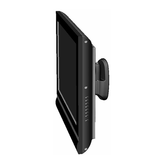
Medium Flat Panel
Pivot/Pitch Wall Mount
Model JWP-V
The JWP Pivot/Pitch wall mount is designed for
mounting a medium sized flat panel display. The mount
can be tilted up and down to 15° of center as well as
pivot left and right.
The JWP is shipped with the VESA
Centris™ interface which is compatible with most
medium flat panels.
To accommodate other mounting patterns in displays,
the JWP comes with a VESA Plate that accommodates
other VESA mounting patterns.
By design, the JWP can be configured to fit your medium
flat panel display, providing that your display does not
exceed the specified weight rating.
BEFORE YOU BEGIN
CAUTION:
To prevent damage to your display and/or the JWP, which could affect or void factory
warranty, thoroughly study all instructions and illustrations before you begin to install the mount. Pay
particular attention to ALL Warnings and Cautions in this document.
The maximum weight allowable for use with the JWP wall mount is 75 lbs (34 kg).
The JWP wall mount is designed to be installed using wall studs or supporting framework. The structure to which
the JWP wall mount is anchored must be capable of supporting five times the total weight of the mount and all
attached equipment.
If you have any questions about this installation, contact Chief Manufacturing at 1-800-582-6480.
®
100mm/100mm
CHIEF MANUFACTURING INC.
1-800-582-6480 952-894-6280 FAX 952-894-6918
8401 EAGLE CREEK PARKWAY, STE. 700
SAVAGE, MINNESOTA 55378 USA
I N S T R U C T I O N S
JWP-V
8832-000134 Rev B
©2006 Chief Manufacturing
www.chiefmfg.com
12/06
Advertisement
Table of Contents

Subscribe to Our Youtube Channel
Related Manuals for CHIEF JWP-V


Summary of Contents for CHIEF JWP-V
-
Page 1: Before You Begin
JWP wall mount is anchored must be capable of supporting five times the total weight of the mount and all attached equipment. If you have any questions about this installation, contact Chief Manufacturing at 1-800-582-6480. CHIEF MANUFACTURING INC. 8832-000134 Rev B 1-800-582-6480 952-894-6280 FAX 952-894-6918 ©2006 Chief Manufacturing... -
Page 2: Dimensional Drawing
Installation Instructions JWP-V IMPORTANT WARNINGS and CAUTIONS! WARNING A WARNING alerts you to the possibility of serious injury or death if you do not follow the instructions. CAUTION A CAUTION alerts you to the possibility of damage or destruction of equipment if you do not follow the corresponding instructions. -
Page 3: Table Of Contents
Installation Instructions JWP-V CONTENTS TOOLS REQUIRED FOR INSTALLATION DIMENSIONAL DRAWING ........2 TOOLS REQUIRED FOR INSTALLATION.... 3 Electric drill and bit set INSPECT UNIT BEFORE INSTALLING....3 Hex wrench set SPECIFICATIONS ........... 3 Phillips screwdriver INTRODUCTION ............4 PARTS............... 5 Level PARTS (Continued).......... -
Page 4: Introduction
Installation Instructions JWP-V 200mm x 200mm INTRODUCTION 200mm x 100mm There are 3 main steps in the JWP-V installation process. These steps are: Selecting an appropriate mounting configuration. Connect display cables Making required adjustments Before starting the installation process, determine the correct mounting hole configuration for your display by reviewing the information located within Table 2 at right. -
Page 5: Parts
Installation Instructions JWP-V PARTS Centris Bracket (See notes) Set Screw (see notes) BAG A BAG B BAG C BAG D BAG E Figure 2. JWP-V Components... -
Page 6: Parts (Continued)
Installation Instructions JWP-V PARTS (Continued) Table 2 shows the individual part and parts bags shipped with JWP parts. Table 2. JWP Parts List Item Description Notes — MSP-MA MOUNT (with Centris bracket) — Interface Bracket — Wall Bracket Use with 40 —... -
Page 7: Secure Wall Bracket
Installation Instructions JWP-V SECURE WALL BRACKET WARNING: It is the responsibility of the installer to verify that the surface to which the mount is anchored will safely support the combined load of all attached components and equipment. Install wall bracket as follows: 1. -
Page 8: Recess Mount Installation
Installation Instructions JWP-V Recess Mount Installation To recess mount Centris Bracket: 1. Lay display down on a flat surface. CAUTION: Make sure surface is clean and free of dirt and debris before laying display down. 2. Select four screws M4 x 20mm screws (60) and four Display spacers (100) from parts bag. -
Page 9: Interface Bracket Installation
Installation Instructions JWP-V Interface Bracket Installation SCREW* DISPLAY The following sections describe how to install the (BAG A OR B) interface bracket (20) for a specific hole-pattern on MOUNTING your display. HOLE This procedure provides a general guideline to follow... -
Page 10: 200Mm X 100Mm Pattern
Installation Instructions JWP-V 200mm x 100mm Pattern For the 200mm x 100mm hole pattern, do the following: 1. Select six flat head M4 screws (60) from Bag A and six spacers (130) from Bag C. 2. Attach the interface bracket (20) using the hole- pattern on the back of your display as shown in Figure 5. -
Page 11: 300Mm X 200Mm Pattern
Installation Instructions JWP-V 300mm x 200mm Pattern For the 300mm x 200mm hole pattern, do the following: 1. Select eight Phillips head M6 screws (110) from Bag B and eight spacers (120) from Bag C. 2. Attach the interface bracket (20) using the hole- pattern on the back of your display as shown in Figure 7. -
Page 12: 200Mm X 200Mm Pattern
Installation Instructions JWP-V 200mm x 200mm Pattern For the 200mm x 200mm hole pattern, do the following: 1. Select the applicable screws as follows: a. If using square hole on interface bracket (20), select four Phillips head M4 screws from Bag A. -
Page 13: Attach Display To Mount (Centris Bracket)
Installation Instructions JWP-V Attach Display to Mount (Centris Bracket) Display After attaching the interface bracket onto the display, the next step is to attach the display to the mount (Centris bracket). Centris To attach the display to the Centris bracket, do the... -
Page 14: Cable Management
Installation Instructions JWP-V CABLE MANAGEMENT Lateral Tension Adjustment Bolt WARNING: Make sure your cables do not run through a pinch points. Do not put your fingers between movable parts. For cable management (not shown), connect and secure power/audio/video cables, making sure to leave sufficient slack to allow for movement of the display.
Need help?
Do you have a question about the JWP-V and is the answer not in the manual?
Questions and answers