Table of Contents

Related Manuals for Rexel S16


Summary of Contents for Rexel S16
-
Page 1: Service Instructions
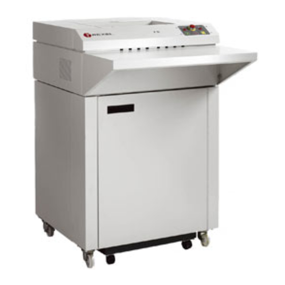
PAPER SHREDDER ILLUSTRATED PARTS LIST SERVICE INSTRUCTIONS Acco Service Division, Halesowen Industrial Estate, Hereward Rise, Halesowen, West Midlands B62 8AN Telephone 0845 658 6600 Fax 0121 501 3991 Page 1 of 43 FEBRUARY 07... -
Page 2: Installation
CONTENTS HEADING PAGE No ILLUSTRATED PARTS LIST INDEX SERVICE INSTRUCTIONS INDEX PREFACE INSTALLATION MODEL SPECIFICATION WIRING DIAGRAMS 39 TO 42 AMENDMENT RECORD Page 2 of 43 FEBRUARY 07... -
Page 3: Illustrated Parts List
PAPER SHREDDER INDEX ILLUSTRATED PARTS LIST SECTION INDEX PAGE No ISSUE NO FRAME AND COVER PANELS ASSEMBLY 6 & 7 CASING ASSEMBLY 8 & 9 CUTTING HEAD 10 & 11 BIN ASSEMBLY 12 & 13 ELECTRICS 14 - 16 PAPER SHREDDER INDEX Page 3 of 43 FEBRUARY 07... - Page 4 SERVICE INSTRUCTIONS SECTION INDEX PAGE No ISSUE NO. INSTALLATION AND SAFETY LUBRICATION OF CUTTING HEAD FEED CHUTE REMOVAL AND REPLACEMENT REMOVAL OF CASING 20 & 21 CUTTING HEAD ADJUSTMENT REPLACING DRIVE BELT REPLACING CUTTING HEAD REPLACING GEARBOX 25 & 26 CUTTERS AND STRIPPER REPLACEMENT MOTOR REPLACEMENT SWITCH PANEL REPLACEMENT...
- Page 5 A competent person should conduct the test and keep a log of all machines tested, the serial number of the machine, the details of the test, the test results and the date the test was carried out. PAPER SHREDDER S16 SECTION 1 ILLUSTRATED PARTS LIST...
- Page 6 M8 x 16 HEX HEAD SCREW D25402 DOOR ASSEMBLY 25419 HINGE RTS37 POP RIVET SCM15 M6 x 12 SCREW HEX HEAD PLN4 M6 PLAIN WASHER SHK4 M6 SHAKEPROOF WASHER ISSUE 2 PAPER SHREDDER S16 SECTION 1 ILLUSTRATED PARTS LIST Page 6 of 43 FEBRUARY 07...
- Page 7 FRAME & COVER PANELS ASSEMBLY ISSUE 2 PAPER SHREDDER S16 SECTION 2 ILLUSTRATED PARTS LIST CASING ASSEMBLY Page 7 of 43 FEBRUARY 07...
-
Page 8: Casing Assembly
25143 FRONT PANEL CASE S/W ASSY SCM31 M6 x 30 HEXAGON HEAD SCREW 25094 FEED SHELF 25075 REAR PANEL M6 HEXAGONAL NUT ISSUE 2 PAPER SHREDDER S16 SECTION 2 ILLUSTRATED PARTS LIST CASING ASSEMBLY Page 8 of 43 FEBRUARY 07... - Page 9 ISSUE 2 PAPER SHREDDER S16 SECTION 3 ILLUSTRATED PARTS LIST CUTTING HEAD Page 9 of 43 FEBRUARY 07...
- Page 10 M8 x 16 HEX HEAD SCREW 45541 DE-JAM KICK PLATE 45539BI SPACER SL22-82 BELT 45667 GEARBOX COMPLETE D25441 REAR HEAD SUPPORT PANEL TRU70 CIRCLIPS D45973 STRIPPERS 45585 COLLARS ISSUE 2 PAPER SHREDDER S16 SECTION 3 ILLUSTRATED PARTS LIST Page 10 of 43 FEBRUARY 07...
-
Page 11: Cutting Head
CUTTING HEAD ISSUE 2 PAPER SHREDDER S16 SECTION 4 ILLUSTRATED PARTS LIST BIN ASSEMBLY Page 11 of 43 FEBRUARY 07... -
Page 12: Bin Assembly
SHK5 M8 SHAKEPROOF WASHER PLN27 WASHER LARGE 25452 BASE REINFORCEMENT 25413 BASE STIFFENER SL18-344 CASTOR STEM INSERT (M8 x 15) SL18-345 CASTOR ISSUE 2 PAPER SHREDDER S16 SECTION 4 ILLUSTRATED PARTS LIST BIN ASSEMBLY Page 12 of 43 FEBRUARY 07... - Page 13 ISSUE 2 PAPER SHREDDER S16 SECTION 5 ILLUSTRATED PARTS LIST ELECTRICS Page 13 of 43 FEBRUARY 07...
- Page 14 CABLE ENTRY CLAMP TO S/N 930900 SL17-127 ENTRY CLAMP BUSH TO S/N 930900 SCM22 SCREW M6 x 20mm HEX HEAD TO S/N 930900 ISSUE 2 PAPER SHREDDER S16 SECTION 5 ILLUSTRATED PARTS LIST ELECTRICS Page 14 of 43 FEBRUARY 07...
-
Page 15: Illustrated Parts
ISSUE 2 PAPER SHREDDER S16 SECTION 5 ILLUSTRATED PARTS LIST ELECTRICS Page 15 of 43 FEBRUARY 07... - Page 16 PART DESCRIPTION QTY COMMENTS D000200 CONTROL PANEL DECAL TO S/N 930900 1000728 S16 SWITCH DECAL FROM S/N 930900 SL10-45 RED NEON INDICATOR LIGHT SL10-62 RED NEON LIGHT 115V SL10-46 RED LED INDICATOR LIGHT TO S/N 930900 SL8-117 EMERGENCY STOP SWITCH...
-
Page 17: Safety Precautions
2. DISCONNECT the electrical mains supply plug from its socket before commencing any services. 3. PAT TEST after any servicing. NOTE: THE ELECTRIC MOTOR IS PROTECTED BY AN AUTOMATIC OVERLOAD CUT- OUT. PAPER SHREDDER S16 SECTION 2 SERVICE INSTRUCTIONS Page 17 of 43... -
Page 18: Lubrication Of Cutting Head
When the machine is used regularly it is recommended that cleaning and oiling is carried out at weekly intervals. At six monthly intervals chains, sprockets and gears should be cleaned and re-coated with Rexel Shredder Oil. Page 18 of 43... -
Page 19: Feed Chute Removal And Replacement
PAPER SHREDDER S16 SECTION 3 SERVICE INSTRUCTIONS FEED CHUTE REMOVAL AND REPLACEMENT 1. Remove the two plastic screw covers (1, fig. 1) by prising upwards with s screwdriver. 2. Remove the two set screws (2, fig. 1), lift front of feed chute, slide forward to unplug at the rear and lift free. -
Page 20: Removal Of Casing
PAPER SHREDDER S16 PAPER SHREDDER S16 SECTION 4 SECTION 4 SERVICE INSTRUCTIONS SERVICE INSTRUCTIONS REMOVAL OF CASING 1. Remove the four screws (1, fig. 2), securing the operating switches assembly to facia panel. 2. Lower the switch assembly to the inside of the machine. - Page 21 Page 21 of 43 FEBRUARY 07...
-
Page 22: Cutting Head Adjustment
PAPER SHREDDER S16 SECTION 5 SERVICE INSTRUCTIONS CUTTING HEAD ADJUSTMENT Ensure that machine is disconnected from the electricity supply. Too much clearance between adjacent cutters can cause incorrect shredding. To rectify:- 1. Remove the casing (section 2 page 4). 2. Prose open locking washers on both shafts on the gearbox end. -
Page 23: Replacing Drive Belt
PAPER SHREDDER S16 SECTION 6 SERVICE INSTRUCTIONS REPLACING DRIVE BELT 1. Remove the casing (section 2, page 4). 2. NOTE: The gearbox pulley and motor drive are on fixed centres. To remove belt, slaken socket set screw securing motor pulley and wind belt off gearbox pulley as shown (fig. 5). -
Page 24: Replacing Cutting Head
PAPER SHREDDER S16 SECTION 7 SERVICE INSTRUCTIONS REPLACING CUTTING HEAD 1. Remove the casing (section 2, page 4). 2. Remove the motor dust cover and lift out the bin full flap. 3. Note and disconnect motor wires from the rear terminal block, capacitor and earth screw. -
Page 25: Replacing Gearbox
PAPER SHREDDER S16 SECTION 8 SERVICE INSTRUCTIONS REPLACING GEARBOX 1. Remove the cutting head unit (section 2 page 7), drive belt (section 2 page 6), and motor (section 2 page 10). 2. Support the cutting head with the gearbox uppermost and remove the screws securing the de-jam plate, gearbox cover and tie rods. - Page 26 PAPER SHREDDER S16 SECTION 8 SERVICE INSTRUCTIONS REPLACING GEARBOX CONT’D Page 26 of 43 FEBRUARY 07...
-
Page 27: Cutters And Stripper Replacement
PAPER SHREDDER S16 SECTION 9 SERVICE INSTRUCTIONS CUTTERS AND STRIPPER REPLACEMENT 1. Remove the cutting head (section 2, page 7) and gearbox and sideframe assembly (section 2 page 8). 2. Remove the 1/1 gears and gearbox cover assembly. 3. Prise open the locking washers and unscrew the locknuts on both shafts. Remove the collars from both shafts and lift away the paper guide plate and infeed extensions. -
Page 28: Motor Replacement
PAPER SHREDDER S16 SECTION 10 SERVICE INSTRUCTIONS MOTOR REPLACEMENT 1. Remove the casing (section 2 page 4), the motor dust guard and the bin full flap. 2. Remove the drive belt and motor pulley (section 2 page 6). 3. Note the wiring connections and disconnect the motor wires from the terminal block, capacitor and the motor earth screw. -
Page 29: Switch Panel Replacement
PAPER SHREDDER S16 SECTION 11 SERVICE INSTRUCTIONS SWITCH PANEL REPLACEMENT 1. Remove the casing (section 2 page 4). 2. Disconnect the ten way ribbon plug from the PCB (1, fig.9). 3. Note the wiring connections and disconnect the four wires (2, fig.9) from the emergency stop switch. -
Page 30: Electronic Adjustments (Reed Switches)
PAPER SHREDDER S16 SECTION 12 SERVICE INSTRUCTIONS ELECTRONIC ADJUSTMENTS (REED SWITCHES) Two sensors are mounted on the printed circuit board (PCB) 91, fig.11), each of which comprise a coil supported on a terminal block and encircling a reed switch. One sensor detects the high current present in the event of a phase failure, the other detecting the high current drawn when the motor stalls due to the jamming of the cutting head. - Page 31 PAPER SHREDDER S16 PAPER SHREDDER S16 SECTION 13 SECTION12 SERVICE INSTRUCTIONS SERVICE INSTRUCTIONS ELECTRONIC ADJUSTMENTS (SENSING COILS) Page 31 of 43 FEBRUARY 07...
- Page 32 Turning the screw clockwise will increase the maximum number of sheets cut. Should any other problems be encountered with the electronics, the complete PCB should be replaced. PAPER SHREDDER S16 SECTION 14 SERVICE INSTRUCTIONS Page 32 of 43...
- Page 33 PAPER SHREDDER S16 SECTION 15 SERVICE INSTRUCTIONS PRINTED CIRCUIT BOARD REPLACEMENT – REED SWITCH 1. Remove casing (ref section 3) 2. Note wiring connections and disconnect the two wires from the terminal block on the PCB (1, fig 12). 3. Disconnect the 8-way plug (2, fig 12) and the 10-way ribbon plug (3, fig 12) from the PCB.
-
Page 34: Contactor Replacement
6. Reconnect wires and plugs as originally fitted (refer to wiring diagrams). 7. Reassemble the machine in the reverse sequence. Carry out PAT test, run the machine and test the operation. PAPER SHREDDER S16 SECTION 16 SERVICE INSTRUCTIONS CONTACTOR REPLACEMENT... - Page 35 5. Replace the contactor(s) as required and reassemble the mechanical interlock and clips. 6. Reconnect wiring as originally fitted (refer to wiring diagrams). 7. Reassemble machine in reverse sequence. Run machine and test for operation. PAPER SHREDDER S16 SECTION 17 SERVICE INSTRUCTIONS Page 35 of 43...
- Page 36 (4, fig 14). 5. Disconnect the leads from the switch. 6. Replace with new switch and connect the wiring. 7. Assemble in reverse sequence and test operation. PAPER SHREDDER S16 SECTION 18 SERVICE INSTRUCTIONS Page 36 of 43...
- Page 37 BIN FULL SWITCH REPLACEMENT 1. Remove casing (section 3). 2. Disconnect switch from the switch located on the left hand side frame. 3. Remove the two screws securing switch and insulating cover to bracket. 4. Replace with the new switch and reconnect the wiring. Test operation. 5.
-
Page 38: Specification
PAPER SHREDDER S16 SECTION 19 FACTORY POTENTIOMETER SETTINGS All machines are set in the factory to achieve the maximum number of sheets cut by adjusting the potentiometer to the value shown below. Individual machines may require adjustment to suit the site conditions, by either increasing or decreasing the resistance value as required. - Page 39 PAPER SHREDDER S16 SECTION 20 WIRING DIAGRAMS Wiring Diagram 115V with Sensing Coil Page 39 of 43 FEBRUARY 07...
- Page 40 PAPER SHREDDER S16 SECTION 20 CONT’D WIRING DIAGRAMS Wiring Diagram 220-240V with Sensing Coil ( From 2/1/95 S/N 690488 To S/N 930900) Page 40 of 43 FEBRUARY 07...
- Page 41 PAPER SHREDDER S16 SECTION 20 CONT’D WIRING DIAGRAMS Wiring Diagram 220-240V with Reed Switch (To 23/12/94 S/N 690488) PAPER SHREDDER S16 SECTION 20 CONT’D Page 41 of 43 FEBRUARY 07...
-
Page 42: Wiring Diagrams
SERVICE INSTRUCTIONS WIRING DIAGRAMS Wiring Diagram 220-240V ( From S/N 930900) Page 42 of 43 FEBRUARY 07... -
Page 43: Amendment Record Sheet
PAPER SHREDDER S16 AMENDMENT RECORD SHEET ISSUE DECRIPTION SERIAL CARO NO Original PCB with sensing coil and new motor 690488 LED PCB and new motor 930900 Page 43 of 43 FEBRUARY 07...
Need help?
Do you have a question about the S16 and is the answer not in the manual?
Questions and answers