Table of Contents
Advertisement
Quick Links
29185D
Hidden Link™ Shelf Top
CFL/LCD Proof IR Receiver
INSTALLATION INSTRUCTIONS
DESCRIPTION
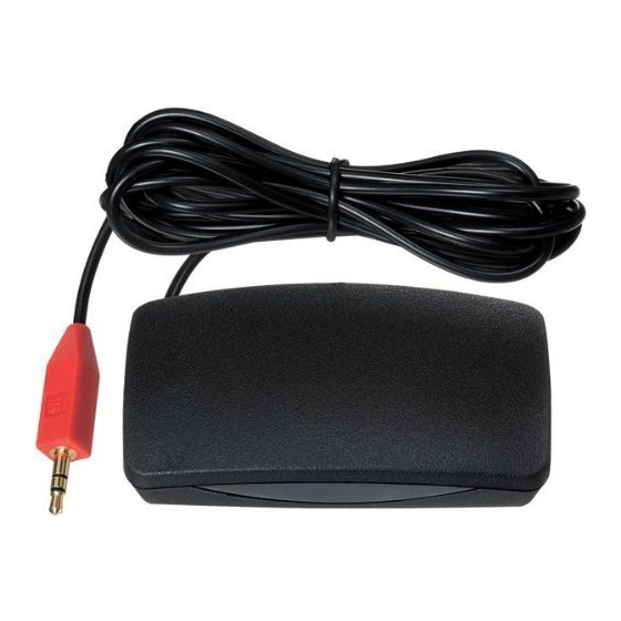
The Hidden Link IR Receiver is a small shelf-top infrared repeater assembly.
It includes an IR receiver and a CB12 Connecting Block. The Hidden Link IR
Receiver is equipped with a 7-foot cable and a 3.5mm stereo mini plug,
which is plugged directly into the "IR RCVR" jack on the CB12. It can also be
plugged into the "AUX" or "IR RCVR" jack of other Xantech connecting
blocks, such as the models 789-44, CB60, and 791-44. The Hidden Link IR
Receiver is primarily intended for use in installations where the connecting
block is within reach of its 7-foot cable – as when installing the Hidden Link
IR Receiver in a cabinet where the controlled equipment is behind closed
doors.
FEATURES
•
Very small package, only 2.00"L x 3.15"W x 0.70"H.
•
System testing red-talk-back LED.
•
Includes CB12 Connecting Block for easy system installation.
SPECIFICATIONS
•
Infrared carrier input frequency bandwidth: 30 - 60kHz.
•
Reception range: Up to 50 feet, depending on conditions.
•
Nominal reception angle: 55 degrees off axis.
•
Cable requirements: See "INSTALLATION" below.
•
Max. transmission length: 1 mile using 18 gauge wire.
•
Maximum current output: 100mA
•
Drives IR emitters through Xantech Connecting Blocks, Controllers, etc.
•
Dimensions: 2.00"x3.15"x0.70" (51mm x 80mm x 18mm)
•
Power requirements: +12VDC, 20mA.
MODEL
INSTALLATION
QUICK-START
A typical system will use an IR receiver, several emitters, and a power supply
all connected to a connecting block.
1. Connect the IR receiver to the "IR RCVR" port on the connecting
block. The 'red' connector is installed to the 'red' plug.
Note: In some extended distances, additional 3-conductor may be required and can
be connected to the terminals on the connecting block.
2. Connect the Emitters to the connecting block. The 'yellow' connector
is installed to the 'yellow' plug.
3. Connect the power supply to the connecting block.
4. Installation complete
LOCAL SYSTEM APPLICATION
In this system a 286D Dual Blink-IR Designer Emitter is shown connected to
the "OUT" jack. A single emitter could also be used, such as the model 282D
or 283D. If expansion beyond two emitters is required, use a Xantech 789-
44, CB60, or 791-44 Connecting Block in place of the CB12. Do not use the
CB12 in this case.
Advertisement
Table of Contents

Subscribe to Our Youtube Channel
Related Manuals for Xantech 29185D


Summary of Contents for Xantech 29185D
-
Page 1: Installation Instructions
Receiver is equipped with a 7-foot cable and a 3.5mm stereo mini plug, or 283D. If expansion beyond two emitters is required, use a Xantech 789- which is plugged directly into the “IR RCVR” jack on the CB12. It can also be 44, CB60, or 791-44 Connecting Block in place of the CB12. - Page 2 CABLE CONNECTIONS REMOTE ROOM APPLICATION 291’s may also be used where the 7-foot cable is not long enough. Simply The CB12 Connecting Block, supplied with the Hidden Link IR Receiver, has cut off the mini plug, strip the leads and splice them to a 3-conductor a three terminal input strip for connection of external infrared receivers extension cable with a terminal block or other means.
- Page 3 • fall within the range of 32kHz to 56kHz, you can adjust the 29185D to match It may be necessary to move either the interfering source of tem for best range performance. The adjustment can be made through the the Hidden Link IR Receiver to achieve proper operation.
- Page 4 [BLANK PAGE] [BLANK PAGE]...
Need help?
Do you have a question about the 29185D and is the answer not in the manual?
Questions and answers