Table of Contents
Advertisement
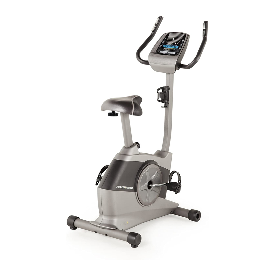
www.healthrider.com
Model No. HREX11912.0
Serial No.
USER’'S MANUAL
Write the serial number in the
space above for reference.
Serial Number Decal
(under frame)
QUESTIONS?
If you have questions, or if parts
are damaged or missing, DO NOT
CONTACT THE STORE; please
contact Customer Care.
IMPORTANT: Please register this
product (see the limited warranty
on the back cover of this manual)
before contacting Customer Care.
CALL TOLL-FREE:
1-888-922-4222
Mon.––Fri. 6 a.m.––6 p.m. MT
Sat. 8 a.m.––4 p.m. MT
ON THE WEB:
www.healthriderservice.com
CAUTION
Read all precautions and instruc-
tions in this manual before using
this equipment. Keep this manual
for future reference.
Advertisement
Table of Contents

Related Manuals for Healthrider H10x Bike


Summary of Contents for Healthrider H10x Bike
- Page 1 Model No. HREX11912.0 Serial No. USER’’S MANUAL Write the serial number in the space above for reference. Serial Number Decal (under frame) QUESTIONS? If you have questions, or if parts are damaged or missing, DO NOT CONTACT THE STORE; please contact Customer Care.
-
Page 2: Table Of Contents
Apply the decal in the location shown. Note: The decal(s) may not be shown at actual size. HEALTHRIDER is a registered trademark of ICON IP, Inc. -
Page 3: Important Precautions
IMPORTANT PRECAUTIONS WARNING: To reduce the risk of serious injury, read all important precautions and instructions in this manual and all warnings on your exercise bike before using your exercise bike. ICON assumes no responsibility for personal injury or property damage sustained by or through the use of this product. -
Page 4: Before You Begin
BEFORE YOU BEGIN Thank you for selecting the new HEALTHRIDER reading this manual, please see the front cover of this ® H10X exercise bike. Cycling is an effective exercise for manual. To help us assist you, note the product model increasing cardiovascular fitness, building endurance, number and serial number before contacting us. -
Page 5: Part Identification Chart
PART IDENTIFICATION CHART Use the drawings below to identify the small parts needed for assembly. The number in parentheses below each drawing is the key number of the part, from the PART LIST near the end of this manual. The number following the key number is the quantity needed for assembly. -
Page 6: Assembly
ASSEMBLY •• To hire an authorized service technician to •• To identify small parts, see page 5. assemble this product, call 1-800-445-2480. In addition to the included tool(s), assembly •• Assembly requires two persons. requires the following tools: one Phillips screwdriver ••... - Page 7 2. Set a sturdy piece of packing material under the front of the Frame (1). Have a second person hold the Frame to prevent it from tipping while you complete this step. Attach the Front Stabilizer (2) to the Frame (1) with two M10 x 75mm Screws (36).
- Page 8 4. Tip: Avoid pinching the wires. Slide the Upright (3) onto the Frame (1). Attach the Upright (3) with four M8 x 18mm Screws (35). Avoid pinching the wires Slide the Top Shield (9) downward and press it onto the Left and Right Shields (17, 18). 5.
- Page 9 6. Using an adjustable wrench, tighten the Adjustment Knob (11) into the Frame (1). Next, loosen the Adjustment Knob (11) a few turns, pull it outward, and insert the Seat Post (5) into the Frame (1). Slide the Seat Post (5) upward or downward to the desired position, and release the Adjustment Knob (11) into one of the adjustment holes in the Seat Post.
- Page 10 8. Identify the Right Handlebar (48) and orient it as shown. Avoid pinching While a second person holds the Right the wire Handlebar (48) near the Upright (3), tie the indi- cated wire tie to the Right Pulse Wire (42). Then, pull the other end of the wire tie upward out of the top of the Upright.
- Page 11 10. While a second person holds the Console (6) near the Upright (3), connect the wires on the Avoid pinching Console to the Upper Wire (32) and to the Right the wire and Left Pulse Wires (42, 28). Insert the excess wire into the Upright (3) or into the Console (6).
- Page 12 12. Identify the Right Pedal (26). Using an adjustable wrench, firmly tighten the Right Pedal (26) clockwise into the right arm of the Crank (13). Tighten the Left Pedal (not shown) counter- clockwise into the left arm of the Crank (not shown).
-
Page 13: How To Use The Exercise Bike
HOW TO USE THE EXERCISE BIKE HOW TO ADJUST THE HEIGHT OF THE SEAT HOW TO ADJUST THE PEDAL STRAPS For effective exercise, the seat should be at the proper To adjust the pedal height. As you pedal, there should be a slight bend in straps, first pull the your knees when the pedals are in the lowest position. - Page 14 CONSOLE DIAGRAM FEATURES OF THE CONSOLE The console also offers a selection of preset work- outs. Each preset workout automatically changes the The advanced console offers an array of features resistance of the pedals as it guides you through an designed to make your workouts more effective and effective workout.
- Page 15 HOW TO USE THE MANUAL MODE 4. Follow your progress with the display. 1. Turn on the console. The left display––This display can show the Press any button or begin pedaling to turn on the elapsed time and the console. approximate number of calories you have When you turn on the console, the display will turn...
- Page 16 5. Measure your heart rate if desired. If your heart rate is not shown, make sure that your hands are positioned as described. Be careful not If there are sheets to move your hands excessively or to squeeze the of plastic on the contacts tightly.
- Page 17 HOW TO USE AN 8-WEEK WEIGHT-LOSS During the workout, the workout profile will show WORKOUT your progress. The flashing segment of the profile represents the current segment of the workout. The 1. Turn on the console. height of the flashing segment indicates the resis- tance level for the current segment.
- Page 18 HOW TO USE A PRESET WORKOUT The resistance level for the next segment will appear in the center display for a few seconds to 1. Turn on the console. alert you. The resistance of the pedals will then change. Press any button or begin pedaling to turn on the console.
-
Page 19: To Use The Sound System
HOW TO USE THE SOUND SYSTEM To play music or audio books through the console sound system while you exercise, plug your audio cable into the jack on the console and into a jack on your MP3 player or CD player; make sure that your audio cable is fully plugged in. -
Page 20: Fcc Information
FCC INFORMATION This equipment has been tested and found to comply with the limits for a Class B digital device, pursuant to part 15 of the FCC Rules. These limits are designed to provide reasonable protection against harmful interference in a residential installation. This equipment generates, uses, and can radiate radio frequency energy and, if not installed and used in accordance with the instructions, may cause harmful interference to radio communications. -
Page 21: Maintenance And Troubleshooting
MAINTENANCE AND TROUBLESHOOTING Inspect and tighten all parts of the exercise bike regu- Using a flat screwdriver, release the tabs along the bot- larly. Replace any worn parts immediately. tom edge of the Top Shield (9) and slide the Top Shield upward. -
Page 22: To Adjust The Drive Belt
HOW TO ADJUST THE DRIVE BELT Remove all the screws from the left and right shields; there are two sizes of screws in the shields——note If the pedals slip while you are pedaling, even while which size of screw you remove from each hole. the resistance is adjusted to the highest level, the drive Then, gently pull the right shield away from the frame. -
Page 23: Exercise Guidelines
EXERCISE GUIDELINES Burning Fat——To burn fat effectively, you must exer- WARNING: cise at a low intensity level for a sustained period of Before beginning this time. During the first few minutes of exercise, your or any exercise program, consult your physi- body uses carbohydrate calories for energy. - Page 24 SUGGESTED STRETCHES The correct form for several basic stretches is shown at the right. Move slowly as you stretch; never bounce. 1. Toe Touch Stretch Stand with your knees bent slightly and slowly bend forward from your hips. Allow your back and shoulders to relax as you reach down toward your toes as far as possible.
- Page 25 NOTES...
-
Page 26: Part List
PART LIST Model No. HREX11912.0 R0912A Key No. Qty. Description Key No. Qty. Description Frame Lower Wire Front Stabilizer Upper Wire Upright M10 x 50mm Hex Screw Stabilizer Cap M4 x 25mm Screw Seat Post M8 x 18mm Screw Console M10 x 75mm Screw Eddy Mechanism M8 Locknut... -
Page 27: Exploded Drawing
EXPLODED DRAWING Model No. HREX11912.0 R0912A 52 46... -
Page 28: Ordering Replacement Parts
ORDERING REPLACEMENT PARTS To order replacement parts, please see the front cover of this manual. To help us assist you, be prepared to provide the following information when contacting us: •• the model number and serial number of the product (see the front cover of this manual) ••...
Need help?
Do you have a question about the H10x Bike and is the answer not in the manual?
Questions and answers
**** I able to buy bearing set for this bike still?