Fluke 345 Calibration Manual
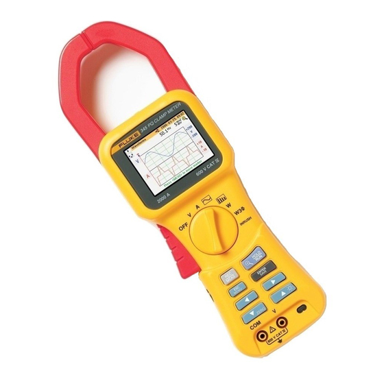
Power quality clamp meter
Hide thumbs
Also See for 345:
- User manual (80 pages) ,
- Technical data manual (12 pages) ,
- Datasheet (8 pages)
Table of Contents
Advertisement
Advertisement
Table of Contents

Related Manuals for Fluke 345


Summary of Contents for Fluke 345
- Page 1 ® Power Quality Clamp Meter Calibration Manual PN 3095315 October 2007 © 2007 Fluke Corporation, All rights reserved. Printed in USA. Product specifications are subject to change without notice. All product names are trademarks of their respective companies.
- Page 2 Fluke authorized resellers shall extend this warranty on new and unused products to end-user customers only but have no authority to extend a greater or different warranty on behalf of Fluke. Warranty support is available only if product is purchased through a Fluke authorized sales outlet or Buyer has paid the applicable international price.
-
Page 3: Table Of Contents
Table of Contents Title Page Introduction......................1 Contacting Fluke....................2 Safety Information ..................... 2 Symbols ......................4 Specifications..................... 4 Cleaning and Maintenance................. 11 Verification Tests....................12 Battery and Battery Eliminator Check............12 Rotary Switch Check ..................13 Date/Time Check................... 13 Display Contrast Check ................. - Page 4 Calibration Manual...
- Page 5 List of Tables Table Title Page Symbols........................4 Required Equipment....................15 Calibration Mode ....................17 Customer-Replaceable Parts and Accessories............28...
- Page 6 Calibration Manual...
- Page 7 List of Figures Figure Title Page Tactile Barrier ......................3 Slider Switch for Line Power Voltage (115 V and 230 V) ........10 Changing the Batteries ................... 12 Startup Screen Noting Calibration Date and Firmware.......... 15 Calibration Mode Screen..................16...
- Page 8 Calibration Manual...
-
Page 9: Introduction
This manual provides the complete verification and adjustment procedure for the 345 Power Quality Clamp Meter (referred to in this manual as the Clamp Meter). The Clamp Meter allows closed-case calibration using reference sources. It measures the reference signals, calculates the correction factors, and stores them in memory. -
Page 10: Contacting Fluke
1-800-363-5853 in Canada +31-402-675-200 in Europe +81-3-3434-0181 in Japan +65-738-5655 in Singapore +1-425-446-5500 from anywhere in the world Or, visit Fluke’s Web site at www.fluke.com To register your product, visit http://register.fluke.com Safety Information In this manual, a Warning identifies conditions and actions that pose hazard(s) to the user. - Page 11 Power Quality Clamp Meter Safety Information • Always connect the Battery Charger/Power Adapter first to the ac outlet before connecting it to the Clamp Meter. • Remove all probes, test leads and accessories not in use. • Do not operate the Clamp Meter around explosive gas or vapor.
-
Page 12: Symbols
Low batteries Batteries fully charged Do not dispose of this product as unsorted Battery Eliminator is connected. municipal waste. Contact Fluke or a qualified recycler for disposal. Earth ground Canadian Standards Association. Double insulated Conforms to relevant Australian standards. - Page 13 Power Quality Clamp Meter Specifications 3 ≤ CF < 5 ............± 5 % rdg ± 5 digits Resolution............0.01 RPL (Ripple) 2 % ≤ RPL< 100 % ......... ± 3 % rdg ± 5 digits 100 % ≤ RPL< 600 % ........± 5 % rdg ± 5 digits Resolution............
- Page 14 Calibration Manual Harmonics THD (Total Harmonic Distortion) 1 % ≤ THD < 100 % ........± 3 % rdg ± 5 digits 100 % ≤ THD < 600 % ........± 5 % rdg ± 5 digits Resolution............0.1 % DF (Distortion Factor) 1 % ≤...
- Page 15 Power Quality Clamp Meter Specifications Frequency ranges .......... 15 Hz to 22 Hz and 45 Hz to 65 Hz Kilowatt Hour (kWHr) Measuring range ..........40,000 kWHr Autorange facility ..........4 kWHr, 40 kWHr, 400 kWHr, 4,000 kWHr, 40,000 kWHr Resolution ............
- Page 16 Digital Output USB Interface to a PC Power Log software for download, analysis and reporting 345 Upgrade Utility for installing a new firmware version Logging Memory Logging Areas............. Three areas that can be used individually or combined into one large area.
- Page 17 Power Quality Clamp Meter Specifications General Data Display Color transmissive LCD 320 x 240 pixels (70 mm diagonal) with 2 level backlight. Power Supply Battery type 1.5 V Alkaline AA MN 1500 or IEC LR6 x 6 Battery life typically: >10 hours (backlight on full) >12 hours (backlight reduced) Battery Eliminator BE345...
- Page 18 Calibration Manual Battery Charger/Power Adapter Note To accommodate connection to various line power sockets, the BE345 Universal Battery Eliminator is equipped with a male plug that must be connected to a line plug adapter appropriate for local use. Since the Charger is isolated, you can use line plug adapters with or without a protective ground terminal.
-
Page 19: Cleaning And Maintenance
To avoid damage to the Clamp Meter, do not apply solvents to the case. The Clamp Meter contains no user serviceable parts. Contact an Authorized Fluke Service Center for repair. See “Contacting Fluke”. Periodically wipe the case with a damp cloth and mild detergent. Do not use abrasives or solvents. -
Page 20: Verification Tests
Verification Tests The following tests verify the functions of the Clamp Meter. If any of the verification tests fail, repair is necessary. For service, see Contacting Fluke. Battery and Battery Eliminator Check With six new AA batteries installed, the battery symbol next to the date on the display should show a indicate full batteries. -
Page 21: Rotary Switch Check
Power Quality Clamp Meter Verification Tests Rotary Switch Check To check the rotary switch: 1. Move the switch from the OFF position and wait for the power-up screen to clear. 2. Move Rotary Switch through each position. Check that each position accesses the correct mode. -
Page 22: Key Pad Check
Calibration Manual Key Pad Check To check the keypad, press each key and verify that each functions as expected. Save and Clear Screenshots To save screenshots: 1. Move the rotary switch to V. 2. Press E to save the screen. 3. -
Page 23: Calibration Adjustment
Calibrator Fluke Model 9100 Universal 0.4 to 600 V >0.25 % accuracy Calibration System with power 4 to 1000 A >0.25 % accuracy functionality, or Fluke 5520 or (with 50 turn coil) equivalent Phase accuracy 0.75 % Coil Fluke 9100-200 10/50 turn coil,... - Page 24 Calibration Manual Once the screen in Figure 4 appears: 1. Press M twice. 2. Press E twice. The calibration mode screen appears, see Figure 5. fcs004.bmp Figure 5. Calibration Mode Screen Use the procedure in the next section to adjust the Clamp Meter.
-
Page 25: Calibration Adjustment Procedure
CLEAR FLASH – right arrow EXIT – down arrow, up arrow EXIT to normal operation. “Apply 0V” Connect Calibrator Hi to “Press <RUN> when ready” 345 V Next State: V2 Connect Calibrator Lo to 345 COM Screen for V2: “VOLTS OFFSETS”... - Page 26 Calibration Manual State Action Comments Screen for V4: “VOLTS COMMON MODE” “V CM” – hex value On completion: “Press <RUN> when ready” Next State: V5 Screen for V5: “VOLTS 4V CAL” “APPLY 4V DC” “Press <RUN> when ready” Next State: V6 Screen for V6: “VOLTS 4V CAL”...
- Page 27 Power Quality Clamp Meter Calibration Adjustment State Action Comments Screen for V10: “VOLTS 400V CAL” “V to ASIC V” – Cal value “V to ASIC A” – Cal value On completion: “Press <RUN> when ready” Next State: V11 Screen for V11: “SAVING VOLTS CAL”...
- Page 28 Calibration Manual State Action Comments Screen for A5: “SENSITIVITY TEST” “APPLY 40A DC” “TO BOTTOM OF JAWS” “Press <RUN> when ready” Next State: A6 Screen for A6: “Gain Adjustment” – ASIC reading “SENSITIVITY TEST” “TOP HALL” – ASIC reading – “BOTTOM HALL”...
- Page 29 Power Quality Clamp Meter Calibration Adjustment State Action Comments Screen for A10: “AMPS ZEROING” “APPLY 0A” “Press <RUN> when ready” Next State: A11 Screen for A11: “AMPS ZEROING” “A to ASIC A, 40A” – hex value On completion: “Press <RUN> when ready” Next State: A12 Screen for A12: “AMPS GAIN”...
- Page 30 Calibration Manual State Action Comments Screen for A16: “AMPS 40A CAL” “APPLY 40A DC” “Press <RUN> when ready” Next State: A17 Screen for A17: “AMPS 40A CAL” “A to ASIC V” – Cal value “A to ASIC A” – Cal value “Press <RUN>...
- Page 31 Power Quality Clamp Meter Calibration Adjustment State Action Comments Screen for C1: Screen showing colours and writing. Right arrow to increase, left arrow to decrease, contrast. Up arrow to toggle backlight. “Press <RUN> when ready” to save. Next State: S6 Screen for T1: As each key is pressed, Self...
-
Page 32: Calibration Verification Procedure
Calibration Manual Calibration Verification Procedure The following sections detail the input levels used to check the Clamp Meter’s calibration. The specification is 100 % of the specified tolerance. Notes For regions with mains power at 50 Hz, inputs should be at 60 Hz. For regions with mains power at 60 Hz, inputs should be at 50 Hz. -
Page 33: Amps Check
Power Quality Clamp Meter Calibration Verification Procedure Amps Check Mode: Amps Input: dc & 60/50 Hz ac signal Internal Accuracy: ± 1.5 % rdg ± 5 dgts for A > 10.0 A ± 0.2 A for A ≤ 10.0 A Calibrator Specification (Amps) -
Page 34: Power Check- Stage 1
Calibration Manual Power Check- Stage 1 Mode: Power Input: 60/50Hz Internal Accuracy: VA: ± 2.5% rdg ± 5 digits W 1 phase < 2 kW + and - 0.08 kW > 2 kW + and - 2.5 %rdg + and - 5 digits W 3 phase <... -
Page 35: Power Check- Stage 2
Power Quality Clamp Meter Calibration Verification Procedure Power Check- Stage 2 Mode: Power Input: 60/50 Hz Internal Accuracy: VAR: > 4kVAR, ±2.5 % rdg ± 5 digits < 4kVAR, ± 0.25 kVAR PF: ± 3° Calibrator Specification (k)W Volts Amps Phase Shift (°) 19.87... -
Page 36: Customer-Replaceable Parts And Accessories
TP74 Banana Jack Test Probes w/cap 2598222 Battery Cover Screws 2599515 Case Screws 2696398 Battery Cover 2696405 Back Label BE345 Universal Battery Eliminator 2441372 International AC Power Connectors 345 Users Manual 2560401 (English, French, Italian, German, Spanish, Portuguese, Simplified Chinese)
Need help?
Do you have a question about the 345 and is the answer not in the manual?
Questions and answers