
Related Manuals for Fluke 28IIEX


Summary of Contents for Fluke 28IIEX
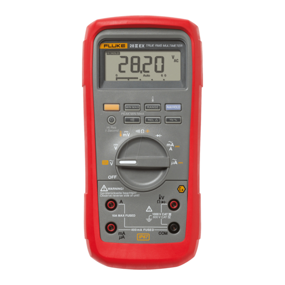
- Page 1 28 II Ex True-rms Digital Multimeter Users Manual November 2011 © 2011 Fluke Corporation. All rights reserved. Specifications are subject to change without notice. All product names are trademarks of their respective companies.
- Page 2 LIMITED WARRANTY AND LIMITATION OF LIABILITY This Fluke product will be free from defects in material and workmanship for three years from the date of purchase. This warranty does not cover fuses, disposable batteries, or damage from accident, neglect, misuse, alteration, contamination, or abnormal conditions of operation or handling.
-
Page 3: Table Of Contents
Table of Contents Title Page Introduction ........................1 How to Contact Fluke ..................... 1 Safety Information ......................2 EX Safety Information ....................2 Errors and Load Restrictions ..................6 Ex-Certification Data ....................7 Features ......................... 9 Automatic Power-Off ....................15 Input Alert™... - Page 4 28 II Ex Users Manual Continuity Tests ......................20 Resistance Measurements ..................22 How to Use Conductance for High Resistance or Leakage Tests ......24 Capacitance Measurements ..................25 Diode Tests ....................... 26 AC or DC Current Measurements ................28 Frequency Measurements ..................
- Page 5 Contents (continued) Frequency ......................... 52 Frequency Counter Sensitivity and Trigger Levels ............ 52 Duty Cycle (Vdc and mVdc) ..................53 Input Characteristics ....................53 MIN MAX Recording ....................54...
- Page 6 28 II Ex Users Manual...
-
Page 7: List Of Tables
List of Tables Table Title Page Symbols ..........................8 Inputs ............................ 9 Rotary Switch Positions ......................10 Pushbuttons .......................... 11 Display Features ........................13 Power-Up Options ......................... 16 Functions and Trigger Levels for Frequency Measurements ..........32 MIN MAX Functions ......................36 Approved Batteries ........................ - Page 8 28 II Ex Users Manual...
- Page 9 List of Figures Figure Title Page Display Features ........................13 AC and DC Voltage Measurements ..................17 Low-Pass Filter ........................19 Continuity Tests ........................21 Resistance Measurements ....................23 Capacitance Measurements ....................25 Diode Tests ........................... 27 Current Measurements ......................29 Components of Duty Cycle Measurements ................
- Page 10 28 II Ex Users Manual viii...
-
Page 11: Introduction
Introduction How to Contact Fluke To contact Fluke, call one of the following telephone WX Warning numbers: Read “Safety Information” before using the Technical Support USA: 1-800-44-FLUKE (1-800- Product. 443-5853) The 28 II Ex Digital Multimeter (the Product) is a compact... -
Page 12: Safety Information
EC declaration of conformity and CAN/CSA-C22.2 No. 61010-1-04 Ex certificate for this product. You can also order IEC Standard No. 61010-1:2001 them from Fluke. Measurement Category III, 1000V, Pollution This manual contains information and safety regulations Degree 2... - Page 13 True-rms Digital Multimeter EX Safety Information WX Warning After you use the Product on a non- intrinsically safe protected circuit, wait To prevent electric shock or personal injury 3 minutes before you take the Product while in Ex-HAZARDOUS areas, follow these into an Ex-hazardous area.
- Page 14 28 II Ex Users Manual WX Warning Use the Product only as specified, or the protection supplied by the Product can To prevent personal injury in mining be compromised. hazardous areas: Do not use the Product in damp or wet Avoid extreme mechanical burdens.
- Page 15 True-rms Digital Multimeter EX Safety Information Do not work alone. Connect the common test lead before the live test lead and remove the live test Do not touch voltages >30 V ac rms, 42 V lead before the common test lead. ac peak, or 60 V dc.
-
Page 16: Errors And Load Restrictions
28 II Ex Users Manual Errors and Load Restrictions WCaution To avoid possible damage to the Product or If there is a question that the safety or integrity of this Product is compromised, remove it from operation and to the equipment under test, follow these guidelines: the Ex-hazardous areas immediately. -
Page 17: Ex-Certification Data
True-rms Digital Multimeter EX Safety Information Ex-Certification Data mA/ A Jack Ex-Type certificate no: = 1.94 V = 65 V = 1000 F = negligible Ex-Designation: = 9.7 A = Internally limited by a 440 mA fuse Power Supply: = 1000 mH L = negligible CE: CE0102 = negligible... - Page 18 Conforms to relevant Australian standards. Conforms to ATEX directive. Inspected and licensed by TÜV Product Conforms to CAN/CSA-C22.2 No. 61010-1 2 ® Æ Services. Amendment 1. Do not dispose of this product as unsorted municipal waste. Go to Fluke’s website for recycling information.
-
Page 19: Features
True-rms Digital Multimeter Features Features Tables 2 through 5 show the features of the Product. Table 2. Inputs grt01.eps Item Terminal Description Input for 0 A to 10.00 A current (10 A to 20 A overload for 30 seconds maximum), ... - Page 20 28 II Ex Users Manual Table 3. Rotary Switch Positions Switch Position Function Any Position When the Product is turned on, the Product model number briefly shows on the display. AC voltage measurement (yellow) Push for low-pass filter (K) DC voltage measurement 600 mV dc voltage range ...
- Page 21 True-rms Digital Multimeter Features Table 4. Pushbuttons Switch Button Function Position Set to capacitance Set to temperature Turn on ac low-pass filter (Yellow) Set dc or ac current Set dc or ac current Change and set the range for the set function. To go to autoranging, hold the button down for position 1 second.
- Page 22 28 II Ex Users Manual Table 4. Pushbuttons (cont.) Switch Button Function Position Continuity Toggle the continuity beeper on and off. Switches between Peak (250 s) and Normal (100 ms) response times. MIN MAX recording Hz, Duty Toggles the Product to trigger on positive or negative slope. Cycle Turns on the button backlight and display backlight, makes them brighter, and turns off the position...
- Page 23 True-rms Digital Multimeter Features Number Feature Indication Negative measurement. In relative mode, this sign shows that the input is less than the stored reference. High voltage present at the input. Appears if the input voltage is 30 V or greater (ac or dc).
- Page 24 28 II Ex Users Manual Table 5. Display Features (cont.) Number Feature Indication Number Feature Indication Degrees Celsius, Degrees Warning: To Low battery. XW Fahrenheit avoid false readings, which could lead to possible electric Displays selected range 610000 mV ...
-
Page 25: Automatic Power-Off
True-rms Digital Multimeter Features Automatic Power-Off Table 5. Display Features (cont.) The Product automatically turns off if you do not turn the rotary switch or push a button for 30 minutes. If MIN MAX Number Feature Indication Recording mode is on, the Product will not turn off. Refer to Table 6 to disable automatic power-off. -
Page 26: Power-Up Options
28 II Ex Users Manual Power-Up Options To set a power-up option, push a button down while you energize the Product. Table 6 shows the power-up option. Table 6. Power-Up Options Button Power-Up Option Disables automatic power-off feature (Product normally powers off in 30 minutes). (Yellow) The Product reads “PoFF”... -
Page 27: How To Make Measurements
True-rms Digital Multimeter How to Make Measurements How to Make Measurements AC Voltage AC and DC Voltage Measurements Switch Box The Product features true-rms measurements, which are accurate for distorted sine waves and other waveforms (with no dc offset) such as square waves, triangle waves, and staircase waves. -
Page 28: Zero Input Behavior Of True-Rms Meters
28 II Ex Users Manual When you measure voltage, the Product puts Low-Pass Filter approximately 10-M (10,000,000 ) impedance in The Product is has an ac low-pass filter. When you parallel with the circuit. This loading effect can cause measure ac voltage or ac frequency, push to set measurement errors in high-impedance circuits. -
Page 29: Temperature Measurements
True-rms Digital Multimeter How to Make Measurements XW Warning W Caution To prevent electric shock or personal injury, To prevent damage to the Product or other do not use the low-pass filter when you equipment, remember that while the Product measure for hazardous voltages. -
Page 30: Continuity Tests
28 II Ex Users Manual Continuity Tests WCaution To prevent damage to the Product or to the equipment under test, disconnect circuit power and discharge all high-voltage capacitors before you do a continuity test. The continuity test has a beeper that sounds when a circuit is complete. - Page 31 True-rms Digital Multimeter How to Make Measurements For in-circuit tests, turn circuit power off. (closed) (open) Activates continuity beeper grt03.eps Figure 4. Continuity Tests...
-
Page 32: Resistance Measurements
28 II Ex Users Manual Resistance Measurements Some guidelines for resistance measurements are: The measured value of a resistor in a circuit can be WCaution different than the resistor's rated value. To prevent damage to the Product or to the equipment under test, disconnect the power The test leads can add 0.1 to 0.2... - Page 33 True-rms Digital Multimeter How to Make Measurements Isolating a Potentiometer In-Circuit Resistance Measurements Circuit Power Disconnect Isolating a Resistor Disconnect grt04.eps Figure 5. Resistance Measurements...
-
Page 34: How To Use Conductance For High Resistance Or Leakage Tests
28 II Ex Users Manual How to Use Conductance for High Resistance or To measure conductance, set up the Product for resistance measurement as shown in Figure 5, then push Leakage Tests C until the nS indicator shows in the display. Conductance, the inverse of resistance, is a measure of how easily current goes through a circuit. -
Page 35: Capacitance Measurements
True-rms Digital Multimeter How to Make Measurements Capacitance Measurements WCaution To prevent damage to the Product or to the Select equipment under test, disconnect circuit Capacitance power and discharge all high-voltage capacitors before you measure capacitance. Use the dc voltage function to make sure that the capacitor is discharged. -
Page 36: Diode Tests
28 II Ex Users Manual Diode Tests WCaution To prevent damage to the Product or to the equipment under test, disconnect circuit power and discharge all high-voltage capacitors before you do a diode test. Use the diode test to examine diodes, transistors, silicon controlled rectifiers (SCRs), and other semiconductor devices. - Page 37 True-rms Digital Multimeter How to Make Measurements Reverse Bias Forward Bias Typical Reading Single Beep Shorted Open Bad Diode Bad Diode grt06.eps Figure 7. Diode Tests...
-
Page 38: Ac Or Dc Current Measurements
28 II Ex Users Manual AC or DC Current Measurements The current ranges of the Product are 600.0 A, 6000 A, 60.00 mA, 400.0 mA, 6.000 A, and 10.00 A. XWWarning To measure current, refer to Figure 8 and continue as To prevent electric shock or personal injury, follows: do not try an in-circuit current measurement... - Page 39 True-rms Digital Multimeter How to Make Measurements Total Current to Circuit Circuit Power: OFF to connect meter. ON for measurement. OFF to disconnect meter. Current Through One Component grt07.eps Figure 8. Current Measurements...
- Page 40 28 II Ex Users Manual Some guidelines for current measurements are: If you use the A terminal, set the rotary switch to mA/A. If you use the mA/ A terminal, set the rotary If the current measurement is 0 A and you are sure switch to ...
-
Page 41: Frequency Measurements
True-rms Digital Multimeter How to Make Measurements Frequency Measurements Some guidelines for frequency measurements are: For frequency measurements, the Product counts the If a measurement shows as 0 Hz or is unstable, the number of times the signal crosses a set voltage level input signal can be below or near the trigger level. - Page 42 28 II Ex Users Manual Table 7. Functions and Trigger Levels for Frequency Measurements Approximate Function Range Typical Application Trigger Level 6 V, 60 V, 5 % of scale Most signals. 600 V, 1000 V 600 mV 30 mV High-frequency 5 V logic signals.
-
Page 43: Duty Cycle Measurements
True-rms Digital Multimeter How to Make Measurements frequency function, Push E to change the slope for Duty Cycle Measurements the counter. Duty cycle (or duty factor) is the percentage of time a For 5-V logic signals, use the 6-V dc range. For 12-V signal is above or below a trigger level in one cycle switching signals in automobiles, use the 60 V dc range. -
Page 44: How To Determine Pulse Width
28 II Ex Users Manual How to Determine Pulse Width HiRes Mode For a periodic waveform (its pattern repeats at equal time On the Product, push H for one second to enter the high- intervals), you can find the time that the signal is high or resolution (HiRes) 4-1/2 digit mode. -
Page 45: Min Max Recording Mode
True-rms Digital Multimeter MIN MAX Recording Mode Min Max records the signal extremes that are longer than MIN MAX Recording Mode 100 ms. The MIN MAX mode records minimum and maximum input values. When the inputs go below the recorded Peak records the signal extremes that are longer than minimum value or above the recorded maximum value, 250 s. - Page 46 28 II Ex Users Manual Table 8. MIN MAX Functions Button MIN MAX Function Enter MIN MAX recording mode. The Product is locked in the range shown before you started MIN MAX mode. (Set the measurement function and range before you enter MIN MAX.) The Product beeps each time a new minimum or maximum value is recorded.
-
Page 47: Autohold Mode
True-rms Digital Multimeter AutoHOLD Mode AutoHOLD Mode Relative Mode When you set relative mode ( ),the Product zeros XWWarning the display and stores the current measurement as the To prevent electrical shock or personal reference for subsequent measurements. The Product is injury, do not use AutoHOLD mode to see if locked into the range selected when you pushed circuits are without power. -
Page 48: Maintenance
28 II Ex Users Manual It is recommended that the Product be calibrated by Fluke Maintenance in two-year intervals. XWWarning Fuse Test To prevent electrical shock or personal As shown in Figure 10, with the Product in the injury, have the Product repaired by ECOM function, put a test lead into the ... -
Page 49: How To Replace The Batteries
True-rms Digital Multimeter Maintenance How to Replace the Batteries Replace the batteries with three AAA Good 0.44 A fuse: 0.995 kΩ to batteries (NEDA 24A IEC LR03). 1.005 kΩ Replace fuse: OL XWWarning To prevent electrical shock or personal injury: Touch top half of input contacts Replace the batteries when the low... - Page 50 28 II Ex Users Manual Replace the batteries as follows, refer to Figure 11: Table 9. Approved Batteries Turn the rotary switch to OFF and remove the test Battery Description Manufacturer leads from the terminals. Duracell Procell MN2400 LR03 Remove the six Torx-head screws from the case Duracell bottom and remove the battery door ().
- Page 51 True-rms Digital Multimeter Maintenance grt10.eps Figure 11. Battery and Fuse Replacement...
-
Page 52: How To Replace The Fuses
Table 10 and Figure 12. Install ONLY specified replacement fuses with the amperage, voltage, and speed ratings shown in To order parts and accessories, refer to the “How to Table 10. The 440-mA fuse is attached to the fuse Contact Fluke” section. - Page 53 True-rms Digital Multimeter Service and Parts Table 10. Replacement Parts Fluke Part or Model Description Qty. Number Battery, AAA 1.5 V 2838018 Fuse, 11 A, 1000 V, FAST 803293 Screw 3861068 Gasket, Battery Door 3439087 28 II Ex Fuse Assembly...
- Page 54 28 II Ex Users Manual Screw AC172 Alligator Clips Battery Door Battery Gasket Door 28 II Ex Holster TL175 Test Lead Set Battery AAA 1.5 V Fuse Assembly Contains 440 mA Fuse Fuse 11 A, 1000 V, Fast 28 II Ex Users Manual CD 28 II Ex 80BK-A Integrated DMM...
- Page 55 W Temperature Probe All accessories in this table are approved for use in explosive hazardous environments. Fluke accessories are available from an authorized Fluke distributor. W Warning - To prevent personal injury or property damage, do not use this accessory in hazardous areas where dust is moved, transported, or conveyed.
-
Page 56: General Specifications
28 II Ex Users Manual General Specifications Maximum voltage between any terminal and earth ground ........... 1000 V rms W Fuse for mA inputs ..........440 mA, 1000 V FAST Fuse W Fuse for A inputs ............. 11 A, 1000 V FAST Fuse Display ................ - Page 57 True-rms Digital Multimeter General Specifications Electromagnetic Compatibility (EN 61326-1:2005) ..In an RF field of 3 V/M, accuracy = specified accuracy +20 counts, except 600 A dc range total accuracy = specified accuracy +60 counts. Temperature not specified Relative Humidity ............0 % to 80 % (0 C to 35 C) 0 % to 70 % (35 C to 50 C) Battery Type ..............
-
Page 58: Detailed Specifications
28 II Ex Users Manual Detailed Specifications For all detailed specifications: Accuracy is specified for 2 years after calibration, at operating temperatures of 18 C to 28 C, with relative humidity at 0 % to 80 %. Accuracy specifications take the form of ([% of Reading] + [Number of least-significant digits]). In the 4 ½-digit mode, multiply the number of least-significant digits (counts) by 10. -
Page 59: Dc Voltage, Conductance, And Resistance
True-rms Digital Multimeter Detailed Specifications DC Voltage, Conductance, and Resistance Function Range Resolution Accuracy mV dc 600.0 mV 0.1 mV (0.1 % + 1) 6.000 V 0.001 V 60.00 V 0.01 V V dc (0.05 % + 1) 600.0 V 0.1 V 1000 V 600.0... -
Page 60: Temperature
28 II Ex Users Manual Temperature [1,2] Range Resolution Accuracy -200 C to +1090 C 0.1 C (1.0 % + 10) -328 F to +1994 F 0.1 F (1.0 % + 18) Does not include error of the thermocouple probe. Accuracy specification assumes ambient temperature stable to 1 C. -
Page 61: Dc Current
True-rms Digital Multimeter Detailed Specifications DC Current Function Range Resolution Burden Voltage Accuracy 600.0 A 0.1 A 100 V/ A (0.2 % + 4) A dc 6000 A 100 V/ A (0.2 % + 2) 60.00 mA 0.01 mA 1.8 mV/mA (0.2 % + 4) mA dc 0.1 mA... -
Page 62: Diode
28 II Ex Users Manual Diode Range Resolution Accuracy 2.000 V 0.001 V (2.0 % + 1) Frequency Range Resolution Accuracy 199.99 Hz 0.01 Hz 1999.9 Hz 0.1 Hz (0.005 % + 1) 19.999 kHz 0.001 kHz 199.99 kHz 0.01 kHz >200 kHz 0.1 kHz Unspecified... -
Page 63: Duty Cycle (Vdc And Mvdc)
True-rms Digital Multimeter Detailed Specifications Duty Cycle (Vdc and mVdc) Range Accuracy Within (0.2 % per kHz + 0.1 %) for rise times <1 s. 0.0 % to 99.9 % 0.5 Hz to 200 kHz, pulse width >2 s. Pulse width range is determined by the frequency by the frequency of the signal. Input Characteristics Input Common Mode... -
Page 64: Min Max Recording
28 II Ex Users Manual MIN MAX Recording Nominal Response Accuracy 100 ms to 80 % Specified accuracy 12 counts for changes >200 ms in duration (dc functions) 120 ms to 80 % Specified accuracy 40 counts for changes >350 ms and inputs >25 % of range (ac functions) Specified accuracy 100 counts for changes >250 s in duration 250 s (peak)
Need help?
Do you have a question about the 28IIEX and is the answer not in the manual?
Questions and answers