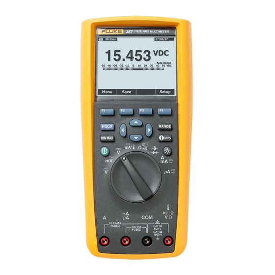
Fluke 287 Getting Started
True-rms digital multimeters
Hide thumbs
Also See for 287:
- Calibration manual (36 pages) ,
- Specifications (2 pages) ,
- Quick reference manual (2 pages)
Table of Contents
Advertisement
Quick Links
See also:
User Manual
Advertisement
Chapters
Table of Contents

Related Manuals for Fluke 287


Summary of Contents for Fluke 287
- Page 1 ® 287/289 True-rms Digital Multimeters Getting Started PN 2748860 June 2007 © 2007 Fluke Corporation, All rights reserved. Printed in USA All product names are trademarks of their respective companies.
- Page 2 Lifetime Limited Warranty Each Fluke 20, 70, 80, 170, 180 and 280 Series DMM will be free from defects in material and workmanship for its lifetime. As used herein, “lifetime” is defined as seven years after Fluke discontinues manufacturing the product, but the warranty period shall be at least ten years from the date of purchase.
-
Page 3: Table Of Contents
Table of Contents Title Page Introduction ........................1 Contacting Fluke ......................1 Safety Information ......................1 Symbols ......................... 3 Turning the Meter On ..................... 4 Setting the Meter’s Language ..................4 Features ......................... 5 Understanding the Push Buttons ................5 Understanding the Display .................. - Page 4 287/289 Getting Started In Case of Difficulty ......................11...
- Page 5 List of Tables Table Title Page Symbols..........................3 Push Buttons ......................... 5 Display Features ........................6 Rotary Switch Positions......................8 Input Terminals........................9 Battery Level Indicator......................10...
- Page 6 287/289 Getting Started List of Figures Figure Title Page Push Buttons......................... 5 Display Features ........................6 Rotary Switch........................8 Input Terminals ........................9...
-
Page 7: Introduction
UL 61010B (2003) Except where noted, the descriptions and instructions in this manual • CAN/CSA-C22.2 No. 61010-1-04 apply to both the Fluke 287 and 289 True-rms Digital Multimeters • IEC/EN 61010-1 2 Edition Pollution Degree 2 (hereafter referred to as “the Meter”). Model 289 appears in all •... - Page 8 287/289 Getting Started • • Remove test leads from the Meter before opening the Do not use the Meter if it operates abnormally. battery door. Protection may be impaired. When in doubt, have the Meter serviced. • Inspect the test leads for damaged insulation or •...
-
Page 9: Symbols
Do not dispose of this product as unsorted municipal waste. Go to Fluke’s website for recycling information. -
Page 10: Turning The Meter On
287/289 Getting Started Setting the Meter’s Language W Caution The Meter comes from the factory with the display language set to To avoid possible damage to the Meter or the equipment English. To select another language, open the setup menu by pressing under test, follow these guidelines: the softkey labeled Setup. -
Page 11: Features
True-rms Digital Multimeters Features Table 2. Push Buttons Features Tables 2 through 5, and the following sections briefly describe the Button Function Meter’s features. Turns the Meter on or off. Understanding the Push Buttons Selects sub-functions and modes related to the The 14 pushbuttons on the front of the Meter activate features that function selected by the rotary switch. -
Page 12: Understanding The Display
Item Function Indication Display features shown in Figure 2 are described in Table 3. Major display features are described in the 287/289 Users Manual contained on Softkey labels Indicates the function of the button just the accompanying CD. below the displayed label. - Page 13 True-rms Digital Multimeters Features Bar Graph Table 3. Display Features (cont.) The analog bar graph functions like the needle on an analog meter, but Item Function Indication without the overshoot. The bar graph updates 30 times per second. Because the graph updates faster than the digital display, it is useful for Mini- Displays the lightning bolt (when necessary) making peak and null adjustments and observing rapidly changing...
-
Page 14: Rotary Switch Positions
287/289 Getting Started Understanding the Rotary Switch Table 4. Rotary Switch Positions Select a primary measurement function by positioning the rotary switch Switch Function to one of the icons around its perimeter. The model 289 offers two Position additional functions: low ohms (Y) and low impedance (LoZ) ac volts. -
Page 15: Using The Input Terminals
True-rms Digital Multimeters Features Using the Input Terminals Table 5. Input Terminals All functions except current use the and COM input terminals. Terminal Description The two current input terminals (A and mA/μA) are used as follows: Input for 0 A to 10.00 A current (20 A for 30 Current from 0 to 400 mA, use the and COM terminals. -
Page 16: Battery Level Indicator
¼ capacity General Maintenance Almost empty (less than one day) For general maintenance refer to the 287/289 Users Manual on the [1] When critically low, a “Replace batteries” pop-up message appears accompanying CD. 15 seconds before the Meter shuts down. -
Page 17: Replacing The Fuses
Include a description of the problem. Fluke assumes no Replacing the Batteries responsibility for damage in transit. To replace the batteries: A Meter under warranty will be repaired or replaced (at Fluke’s option) and returned at no charge. See the registration card for warranty terms. - Page 18 287/289 Getting Started...
- Page 19 ® 287/289 True-rms Digital Multimeters PN 2748860 June 2007 Parts and Specifications © 2007 Fluke Corporation, All rights reserved. Printed in USA All product names are trademarks of their respective companies.
- Page 21 Table of Contents Title Page Parts..........................1 General Specifications ....................5 AC Voltage Specifications ..................7 AC Current Specifications ..................8 DC Voltage Specification ................... 9 DC Current Specifications ..................10 Resistance Specifications..................11 Temperature Specifications ..................11 Capacitance and Diode Test Specifications .............. 12 Frequency Counter Specifications................
- Page 22 287/289 Getting Started...
-
Page 23: Parts
Parts Replacement parts and accessories are shown in Tables 1 and 2 and Figure 1. To order parts and accessories, refer to the “Contacting Fluke” section. Table 1. Replacement Parts Item Fluke Part/Model Description Qty. Number Knob 2798434 2798418 (289) - Page 24 Alligator Clips, one black and one red 1670641 (Red) Manual, Manual Pack, Fluke 287/289 2748851 287/289 Users Manual CD 2748872 WTo ensure safety, use exact replacement only. [1] The Users and Getting Started manuals are available through www.Fluke.com. Click on Support and then Product Manuals.
- Page 25 True-rms Digital Multimeters Parts 4 PL 2 PL 6 PL est40.eps Figure 1. Replaceable Parts...
- Page 26 Carrying Case, Soft TL76 4 mm Diameter Test Leads TL220 Industrial Test Lead Set TL224 Test Lead Set, Heat-Resistant Silicone Test Probes, Flat Blade, Slim Reach Test Probes, 4 mm diameter, Slim Reach Fluke accessories are available from an authorized Fluke distributor.
-
Page 27: General Specifications
Maximum voltage between any Terminal and Earth Ground: 1000 V W Fuse Protection for mA or μA inputs .....0.44 A (44/100 A, 440 mA), 1000 V FAST Fuse, Fluke specified part only W Fuse Protection for A input......11 A, 1000 V FAST Fuse, Fluke specified part only Battery Type............6 AA Alkaline batteries, NEDA 15A IEC LR6... - Page 28 287/289 Getting Started Electromagnetic Compatibility Standards (EMC) European EMC............EN61326-1 Australian EMC ...........; N10140 US FCC...............FCC CFR47: Part 15 CLASS A Certifications ............UL, CE, CSA, ; (N10140), Accuracy: Accuracy is specified for a period of one year after calibration, at 18 °C to 28 °C (64 °F to 82 °F), with relative humidity to 90 %. Accuracy specifications are given as: ±( [ % of reading ] + [ number of least significant digits ] ).
-
Page 29: Ac Voltage Specifications
True-rms Digital Multimeters General Specifications AC Voltage Specifications Accuracy Function Range Resolution 20 to 45 Hz 45 to 65 Hz 65 Hz to 10 kHz 10 to 20 kHz 20 to 100 kHz AC mV 50 mV 0.001 mV 1.5 % + 60 0.3 % + 25 0.4 % + 25 0.7 % + 40... -
Page 30: Ac Current Specifications
287/289 Getting Started AC Current Specifications Accuracy Function Range Resolution 20 to 45 Hz 45 to 1 kHz 1 to 20 kHz 20 to 100 kHz AC μA 500 μA 0.01 μA 1 % + 20 0.6 % + 20 0.6 % + 20... -
Page 31: Dc Voltage Specification
True-rms Digital Multimeters General Specifications DC Voltage Specification Accuracy Function Range Resolution AC over DC, DC over AC, AC + DC [1][2] 20 to 45 Hz 45 Hz to 1 kHz 1 to 20 kHz 20 to 35 kHz DC mV 50 mV 0.001 mV 0.05 % + 20... -
Page 32: Dc Current Specifications
287/289 Getting Started DC Current Specifications Accuracy AC over DC, DC over AC, AC + DC Function Range Resolution [1][3] 20 to 45 Hz 45 Hz to 1 kHz 1 to 20 kHz 20 to 100 kHz DC μA 500 μA 0.01 μA... -
Page 33: Resistance Specifications
True-rms Digital Multimeters General Specifications Resistance Specifications Function Range Resolution Accuracy 50 Ω [1][4] 0.001 Ω Resistance 0.15 % + 20 500 Ω 0.01 Ω 0.05 % + 10 0.05 % + 2 5 kΩ 0.0001 kΩ 0.05 % + 2 50 kΩ... -
Page 34: Capacitance And Diode Test Specifications
287/289 Getting Started Capacitance and Diode Test Specifications Function Range Resolution Accuracy Capacitance 1 nF 0.001 nF 1 % + 5 10 nF 0.01 nF 1 % + 5 100 nF 0.1 nF 1 % + 5 1 μF 0.001 μF 1 % + 5 10 μF... -
Page 35: Frequency Counter Specifications
True-rms Digital Multimeters General Specifications Frequency Counter Specifications Function Range Resolution Accuracy Frequency 99.999 Hz 0.001 Hz 0.02 % + 5 (0.5 Hz to 999.99 kHz, pulse 999.99 Hz 0.01 Hz 0.005 % + 5 width >0.5 μs) 9.9999 kHz 0.0001 Hz 0.005 % + 5 99.999 kHz... -
Page 36: Frequency Counter Sensitivity
287/289 Getting Started Frequency Counter Sensitivity Approximate Voltage Sensitivity Approximate DC (rms sine wave) Input Range AC Bandwidth DC Bandwidth Trigger Levels 15 Hz to 100 kHz 50 mV 5 mV 1 MHz 5 mV & 20 mV 600 kHz... -
Page 37: Input Characteristics
True-rms Digital Multimeters General Specifications Input Characteristics Common Mode Overload Function Input Impedance Rejection Ratio Normal Mode Rejection Protection (1 kΩ unbalance) 1000 V 10 MΩ <100 pF >120 dB at dc, 50 Hz or 60 Hz >60 dB at 50 Hz or 60 Hz 1000 V 10 MΩ... -
Page 38: Min Max, Recording, And Peak Specifications
287/289 Getting Started MIN MAX, Recording, and Peak Specifications Function Nominal Response Accuracy Specified accuracy ±12 counts for changes >425 ms in duration in manual 200 ms to 80% (dc function) range. MIN MAX, Recording Specified Accuracy ±40 counts for changes >1.5 s in duration in manual 350 ms to 80 % (ac function) range.
Need help?
Do you have a question about the 287 and is the answer not in the manual?
Questions and answers