ZyXEL Communications GS-4012F User Manual
Hide thumbs
Also See for GS-4012F:
- User manual (327 pages) ,
- Specifications (6 pages) ,
- Quick start manual (22 pages)
Table of Contents
Troubleshooting

Related Manuals for ZyXEL Communications GS-4012F


Summary of Contents for ZyXEL Communications GS-4012F
- Page 1 GS-4012F Ethernet Switch User’s Guide Version 3.60 4/2005...
-
Page 2: Copyright
ZyXEL Communications Corporation. Published by ZyXEL Communications Corporation. All rights reserved. Disclaimer ZyXEL does not assume any liability arising out of the application or use of any products, or software described herein. -
Page 3: Interference Statements And Warnings
GS-4012F User’s Guide Interference Statements and Warnings FCC Statement This switch complies with Part 15 of the FCC rules. Operation is subject to the following two conditions: 1 This switch may not cause harmful interference. 2 This switch must accept any interference received, including interference that may cause undesired operations. -
Page 4: Safety Warnings
GS-4012F User’s Guide 2 Select your product from the drop-down list box on the ZyXEL home page to go to that product's page. 3 Select the certification you wish to view from this page. Registration Register your product online for free future product updates and information at www.zyxel.com for global products, or at www.us.zyxel.com for North American products. -
Page 5: Zyxel Limited Warranty
GS-4012F User’s Guide ZyXEL Limited Warranty ZyXEL warrants to the original end user (purchaser) that this product is free from any defects in materials or workmanship for a period of up to two years from the date of purchase. During the warranty period, and... -
Page 6: Customer Support
GS-4012F User’s Guide Customer Support Please have the following information ready when you contact customer support. • Product model and serial number. • Warranty Information. • Date that you received your device. • Brief description of the problem and the steps you took to solve it. - Page 7 GS-4012F User’s Guide METHOD SUPPORT E-MAIL TELEPHONE* WEB SITE REGULAR MAIL SALES E-MAIL FTP SITE LOCATION support@zyxel.co.uk +44 (0) 8702 909090 www.zyxel.co.uk ZyXEL Communications UK Ltd.,11 The Courtyard, sales@zyxel.co.uk +44 (0) 8702 909091 ftp.zyxel.co.uk UNITED KINGDOM Eastern Road, Bracknell, 0906 7370001(UK...
-
Page 8: Table Of Contents
GS-4012F User’s Guide Table of Contents Copyright ........................1 Interference Statements and Warnings..............2 ZyXEL Limited Warranty ..................4 Customer Support ....................5 Table of Contents ..................... 7 List of Figures ......................19 List of Tables ......................25 Preface ........................29 Chapter 1 Getting to Know Your Switch................ - Page 9 GS-4012F User’s Guide 3.1.1 Console Port ................... 43 3.1.2 Gigabit Ethernet Ports ................44 3.1.2.1 Default Ethernet Settings ..............44 3.1.3 SFP Slots ....................44 3.1.3.1 Transceiver Installation ..............44 3.1.3.2 Transceiver Removal ..............45 3.2 Rear Panel ......................46 3.2.1 Power Connector ..................
- Page 10 GS-4012F User’s Guide 7.4 Introduction to VLANs ..................73 7.5 IGMP Snooping ....................74 7.6 Switch Setup Screen ..................74 7.7 IP Setup ......................76 7.7.1 IP Interfaces .................... 76 7.8 Port Setup ......................78 Chapter 8 VLAN ........................81 8.1 Introduction to IEEE 802.1Q Tagged VLANs...
- Page 11 GS-4012F User’s Guide Chapter 12 Bandwidth Control....................101 12.1 Configuring ....................101 Chapter 13 Broadcast Storm Control ..................103 13.1 Overview ......................103 13.2 Broadcast Storm Control Setup ..............103 Chapter 14 Mirroring ....................... 105 14.1 Overview ......................105 14.2 Port Mirroring Configuration ................105 Chapter 15 Link Aggregation ....................
- Page 12 GS-4012F User’s Guide Chapter 19 Policy Rule......................125 19.1 Overview ....................... 125 19.1.1 DiffServ ....................125 19.1.2 DSCP and Per-Hop Behavior ............... 125 19.2 Configuring Policy Rules ................125 19.3 Viewing and Editing Policy Configuration ............128 19.4 Policy Example ....................129 Chapter 20 Queuing Method....................
- Page 13 GS-4012F User’s Guide 24.4 Configuring OSPF Areas ................150 24.4.1 Viewing OSPF Area Information Table ..........151 24.5 Configuring OSPF Interfaces ............... 152 24.6 OSPF Virtual Links ..................153 Chapter 25 IGMP........................155 25.1 Overview ......................155 25.2 Configuring ....................155 Chapter 26 DVMRP ........................
- Page 14 GS-4012F User’s Guide Chapter 30 VRRP ........................173 30.1 Overview ......................173 30.2 Viewing VRRP Status .................. 174 30.3 Configuring VRRP ..................175 30.3.1 IP Interface Setup ................175 30.3.2 VRRP Parameters ................176 30.3.2.1 Advertisement Interval ............... 176 30.3.2.2 Priority ..................176 30.3.2.3 Preempt Mode ................
- Page 15 GS-4012F User’s Guide 32.6.1 Requirements for Using SSH ............... 195 32.7 Introduction to HTTPS ................... 195 32.8 HTTPS Example .................... 196 32.8.1 Internet Explorer Warning Messages ........... 196 32.8.2 Netscape Navigator Warning Messages ..........197 32.8.3 The Main Screen .................. 198 32.9 Service Port Access Control ................
- Page 16 GS-4012F User’s Guide Chapter 39 Introducing the Commands ................219 39.1 Overview ......................219 39.1.1 Switch Configuration File ..............219 39.2 Accessing the CLI ..................219 39.2.1 Access Priority ..................220 39.2.2 The Console Port ................. 220 39.2.2.1 Initial Screen ................220 39.2.3 Telnet ....................
- Page 17 GS-4012F User’s Guide 40.6.4 Resetting to the Factory Default ............254 40.7 no Command Examples ................255 40.7.1 no mirror-port ..................255 40.7.2 no https timeout ..................255 40.7.3 no trunk ....................256 40.7.4 no port-access-authenticator ..............256 40.7.5 no ssh ....................257 40.8 interface Commands ..................
- Page 18 GS-4012F User’s Guide 41.5.4.2 Forwarding Process Example ............. 273 41.5.5 Delete VLAN ID ..................273 41.6 Enable VLAN ....................274 41.7 Disable VLAN ....................274 41.8 Show VLAN Setting ..................274 Chapter 42 Troubleshooting....................277 42.1 Problems Starting Up the Switch ..............277 42.2 Problems Accessing the Switch ..............
- Page 19 GS-4012F User’s Guide Table of Contents...
-
Page 20: List Of Figures
GS-4012F User’s Guide List of Figures Figure 1 Backbone Application ................35 Figure 2 Bridging Application ................36 Figure 3 High Performance Switched Workgroup Application ....... 36 Figure 4 Tag-based VLAN Application ..............37 Figure 5 Shared Server Using VLAN Example ............37 Figure 6 Attaching Rubber Feet ................ - Page 21 GS-4012F User’s Guide Figure 39 Spanning Tree Protocol: Status ............. 97 Figure 40 Spanning Tree Protocol: Configuration ..........98 Figure 41 Bandwidth Control ................. 101 Figure 42 Broadcast Storm Control ............... 103 Figure 43 Mirroring ....................105 Figure 44 Link Aggregation Control Protocol Status ..........108 Figure 45 Link Aggregation Control Protocol: Configuration .........
- Page 22 GS-4012F User’s Guide Figure 82 DHCP Server Network Example ............170 Figure 83 DHCP Server Configuration Example ........... 170 Figure 84 DHCP: Relay ..................171 Figure 85 DHCP Relay Network Example ............. 172 Figure 86 DHCP Relay Configuration Example ............. 172 Figure 87 VRRP: Example 1 .................
- Page 23 GS-4012F User’s Guide Figure 125 Diagnostic .................... 203 Figure 126 Clustering Application Example ............205 Figure 127 Cluster Management: Status ............... 206 Figure 128 Cluster Management: Cluster Member Web Configurator Screen ..207 Figure 129 Example: Uploading Firmware to a Cluster Member Switch ....208 Figure 130 Clustering Management Configuration ..........
- Page 24 GS-4012F User’s Guide Figure 168 bandwidth-limit Command Example ............ 260 Figure 169 mirror Command Example ..............261 Figure 170 gvrp Command Example ..............262 Figure 171 ingress-check Command Example ............262 Figure 172 frame-type Command Example ............263 Figure 173 spq Command Example ..............263 Figure 174 wrr Command Example ...............
- Page 25 GS-4012F User’s Guide List of Figures...
-
Page 26: List Of Tables
GS-4012F User’s Guide List of Tables Table 1 Front Panel ....................43 Table 2 Front Panel LEDs ..................47 Table 3 Navigation Panel Sub-links Overview ............51 Table 4 Web Configurator Screen Sub-links Details ..........51 Table 5 Navigation Panel Links ................52 Table 6 Status ...................... - Page 27 GS-4012F User’s Guide Table 39 Policy: Summary Table ................128 Table 40 Physical Queue Priority ................131 Table 41 Queuing Method ..................133 Table 42 VLAN Tag Format ................... 136 Table 43 Single and Double Tagged 802.11Q Frame Format ........ 137 Table 44 802.1Q Frame ..................
- Page 28 GS-4012F User’s Guide Table 82 FTP Upload to Cluster Member Example ..........208 Table 83 Clustering Management Configuration ........... 209 Table 84 MAC Table ....................212 Table 85 IP Table ....................214 Table 86 ARP Table ....................216 Table 87 Routing Table Status ................217 Table 88 Command Summary: User Mode ............
- Page 29 GS-4012F User’s Guide List of Tables...
-
Page 30: Preface
• For brevity’s sake, we will use “e.g.,” as a shorthand for “for instance”, and “i.e.,” for “that is” or “in other words” throughout this manual. • The GS-4012F Ethernet Switch may be referred to as “the GS-4012F” or “the switch” in this User’s Guide. -
Page 31: User Guide Feedback
Help us help you. E-mail all User Guide-related comments, questions or suggestions for improvement to techwriters@zyxel.com.tw or send regular mail to The Technical Writing Team, ZyXEL Communications Corp., 6 Innovation Road II, Science-Based Industrial Park, Hsinchu, 300, Taiwan. Thank you. -
Page 32: Getting To Know Your Switch
This chapter introduces the main features and applications of the switch. 1.1 Introduction The GS-4012F is a stand-alone layer-3 Gigabit Ethernet switch with 12 min-GBIC slots and four Gigabit/mini-GBIC ports. By integrating router functions, the GS-4012F performs wire- speed layer-3 routing in addition to layer-2 switching. - Page 33 GS-4012F User’s Guide VLAN Stacking Use VLAN stacking to add an outer VLAN tag to the inner IEEE 802.1Q tagged frames that enter the network. By tagging the tagged frames (“double-tagged” frames), the service provider can manage up to 4,094 VLAN groups with each group containing up to 4,094 customer VLANs.
- Page 34 GS-4012F User’s Guide IP Multicast With IP multicast, the switch delivers IP packets to a group of hosts on the network - not everybody. In addition, the switch can send packets to Ethernet devices that are not VLAN- aware by untagging (removing the VLAN tags) IP multicast packets.
-
Page 35: Hardware Features
GS-4012F User’s Guide Maintenance and Management Features • Access Control You can specify the service(s) and computer IP address(es) to control access to the switch for management. • Cluster Management Cluster management (also known as iStacking) allows you to manage switches through one switch, called the cluster manager. -
Page 36: Applications
All users that need high bandwidth can connect to high-speed department servers via the switch. You can provide a super-fast uplink connection by using a Gigabit Ethernet/mini-GBIC port on the GS-4012F. Moreover, the switch eases supervision and maintenance by allowing network managers to centralize multiple servers at a single location. -
Page 37: High Performance Switching Example
GS-4012F User’s Guide Figure 2 Bridging Application 1.4.3 High Performance Switching Example The switch is ideal for connecting two networks that need high bandwidth. In the following example, use trunking to connect these two networks. Switching to higher-speed LANs such as ATM (Asynchronous Transmission Mode) is not feasible for most people due to the expense of replacing all existing Ethernet cables and adapter cards, restructuring your network and complex maintenance. -
Page 38: Tag-Based Vlan Example
GS-4012F User’s Guide 1.4.4.1 Tag-based VLAN Example Ports in the same VLAN group share the same frame broadcast domain thus increase network performance through reduced broadcast traffic. VLAN groups can be modified at any time by adding, moving or changing ports without any re-cabling. - Page 39 GS-4012F User’s Guide Chapter 1 Getting to Know Your Switch...
-
Page 40: Hardware Installation And Connection
GS-4012F User’s Guide H A P T E R Hardware Installation and Connection This chapter shows you how to install the hardware and make port connections. 2.1 Freestanding Installation 1 Make sure the switch is clean and dry. 2 Set the switch on a smooth, level surface strong enough to support the weight of the switch and the connected cables. -
Page 41: Mounting The Switch On A Rack
GS-4012F User’s Guide 2.2 Mounting the Switch on a Rack This section lists the rack mounting requirements and precautions and describes the installation steps. 2.2.1 Rack-mounted Installation Requirements • Two mounting brackets. • Eight M3 flat head screws and a #2 Philips screwdriver. -
Page 42: Figure 8 Mounting The Switch On A Rack
GS-4012F User’s Guide Figure 8 Mounting the Switch on a Rack 2 Using a #2 Philips screwdriver, install the M5 flat head screws through the mounting bracket holes into the rack. 3 Repeat steps to attach the second mounting bracket on the other side of the rack. - Page 43 GS-4012F User’s Guide Chapter 2 Hardware Installation and Connection...
-
Page 44: Chapter 3 Hardware Overview
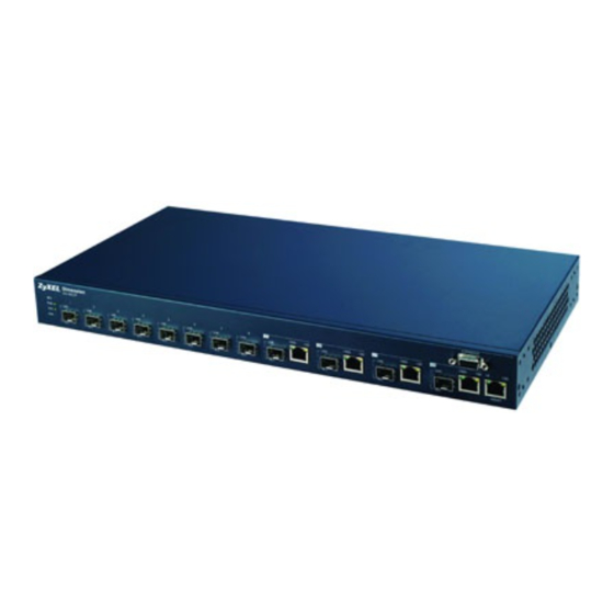
GS-4012F User’s Guide H A P T E R Hardware Overview This chapter describes the front panel and rear panel of the switch and shows you how to make the hardware connections. 3.1 Front Panel Connection The figure below shows the front panel of the switch. -
Page 45: Gigabit Ethernet Ports
GS-4012F User’s Guide 3.1.2 Gigabit Ethernet Ports The switch has four 100/1000Mbps auto-negotiating, auto-crossover Gigabit Ethernet ports. In 10/100/1000 Mbps Gigabit Ethernet, the speed can be 100Mbps or 1000Mbps and the duplex mode can be half duplex (for 100 Mbps) or full duplex. -
Page 46: Transceiver Removal
GS-4012F User’s Guide Figure 10 Transceiver Installation Example 2 Press the transceiver firmly until it clicks into place. 3 The switch automatically detects the installed transceiver. Check the LEDs to verify that it is functioning properly. Figure 11 Installed Transceiver 3.1.3.2 Transceiver Removal... -
Page 47: Rear Panel
GS-4012F User’s Guide Figure 13 Transceiver Removal Example 3.2 Rear Panel The following figure shows the rear panel of the switch. The rear panel contains a connector for backup power supply (BPS) and the power receptacle. Figure 14 Rear Panel 3.2.1 Power Connector... -
Page 48: Front Panel Leds
GS-4012F User’s Guide 3.3 Front Panel LEDs The LEDs are located on the front panel. The following table describes the LEDs on the front panel. Table 2 Front Panel LEDs COLOR STATUS DESCRIPTION Green Blinking The system is receiving power from the backup power supply. - Page 49 GS-4012F User’s Guide Chapter 3 Hardware Overview...
-
Page 50: The Web Configurator
GS-4012F User’s Guide H A P T E R The Web Configurator This section introduces the configuration and functions of the web configurator. 4.1 Introduction The web configurator is an HTML-based management interface that allows easy switch setup and management via Internet browser. Use Internet Explorer 6.0 and later or Netscape Navigator 7.0 and later versions. -
Page 51: The Status Screen
GS-4012F User’s Guide 4 Click OK to view the first web configurator screen. 4.3 The Status Screen The Status screen is the first screen that displays when you access the web configurator. The following figure shows the navigating components of a web configurator screen. -
Page 52: Table 3 Navigation Panel Sub-Links Overview
GS-4012F User’s Guide Table 3 Navigation Panel Sub-links Overview ADVANCED BASIC SETTING IP APPLICATION MANAGEMENT APPLICATION The following table lists the various web configurator screens within the sub-links. Table 4 Web Configurator Screen Sub-links Details ADVANCED BASIC SETTING IP APPLICATION... -
Page 53: Table 5 Navigation Panel Links
GS-4012F User’s Guide Table 4 Web Configurator Screen Sub-links Details (continued) ADVANCED BASIC SETTING IP APPLICATION MANAGEMENT APPLICATION Broadcast Storm Control DHCP Server Status Cluster Management Status Mirroring DHCP Server Cluster Management Configuration Link Aggregation DHCP Relay MAC Table Link Aggregation... - Page 54 GS-4012F User’s Guide Table 5 Navigation Panel Links (continued) LINK DESCRIPTION Mirroring This link takes you to screens where you can copy traffic from one port or ports to another port in order that you can examine the traffic from the first port without...
-
Page 55: Change Your Password
GS-4012F User’s Guide Table 5 Navigation Panel Links (continued) LINK DESCRIPTION IP Table This link takes you to a screen where you can view the IP addresses (and types) of devices attached to what ports and VLAN IDs. ARP Table This link takes you to a screen where you can view the MAC addresses –... -
Page 56: Resetting The Switch
GS-4012F User’s Guide 6 Assigning minimum bandwidth to the CPU port. If you limit bandwidth to the CPU port, you may find that the switch performs sluggishly or not at all. Note: Be careful not to lock yourself and others out of the switch. -
Page 57: Logging Out Of The Web Configurator
GS-4012F User’s Guide Figure 18 Resetting the Switch: Via the Console Port Bootbase Version: V1.0 | 11/26/2004 15:56:35 RAM:Size = 64 Mbytes FLASH: Intel 32M ZyNOS Version: V3.60(LL.0)b2 | 01/18/2005 00:39:28 Press any key to enter debug mode within 3 seconds. -
Page 58: Initial Setup Example
GS-4012F User’s Guide H A P T E R Initial Setup Example This chapter shows how to set up the switch for an example network. 5.1 Overview The following lists the configuration steps for the example network: • Configure an IP interface •... -
Page 59: Configuring Dhcp Server Settings
GS-4012F User’s Guide 2 Open your web browser and enter 192.168.0.1 (the default MGMT port IP address) in the address bar to access the web configurator. See Section 4.2 on page 49 for more information. 3 Click Basic Setting and IP Setup in the navigation panel. -
Page 60: Creating A Vlan
GS-4012F User’s Guide 5.1.3 Creating a VLAN VLANs confine broadcast frames to the VLAN group in which the port(s) belongs. You can do this with port-based VLAN or tagged static VLAN with fixed port members. In this example, you want to configure port 10 as a member of VLAN 2. -
Page 61: Setting Port Vid
GS-4012F User’s Guide 2 In the Static VLAN screen, select ACTIVE, enter a descriptive name in the Name field and enter 2 in the VLAN Group ID field for the Sales network. Note: The VLAN Group ID field in this screen and the VID field in the IP Setup screen refer to the same VLAN ID. -
Page 62: Enabling Rip
GS-4012F User’s Guide 1 Click Advanced Applications and VLAN in the navigation panel. Then click the VLAN Port Setting link. 2 Enter 2 in the PVID field for port 10 and click Apply to save the settings. 5.1.5 Enabling RIP To exchange routing information with other routing devices across different routing domains, enable RIP (Routing Information Protocol) in the RIP screen. - Page 63 GS-4012F User’s Guide Chapter 5 Initial Setup Example...
-
Page 64: System Status And Port Statistics
GS-4012F User’s Guide H A P T E R System Status and Port Statistics This chapter describes the system status (web configurator home page) and port details screens. 6.1 Overview The home screen of the web configurator displays a port statistical summary with links to each port showing statistical details. -
Page 65: Port Details
GS-4012F User’s Guide Table 6 Status LABEL DESCRIPTION System up Time This field shows how long the system has been running since the last time it was started. Port This identifies the Ethernet port. Click a port number to display the Port Details... -
Page 66: Figure 24 Status: Port Details
GS-4012F User’s Guide Figure 24 Status: Port Details The following table describes the labels in this screen. Table 7 Status: Port Details LABEL DESCRIPTION Port Info Link This field displays the speed (either 10M for 10Mbps, 100M for 100Mbps or 1000M for 1000Mbps) and the duplex (F for full duplex or H for half duplex). - Page 67 GS-4012F User’s Guide Table 7 Status: Port Details (continued) LABEL DESCRIPTION Up Time This field shows the total amount of time the connection has been up. Tx Packet The following fields display detailed information about packets transmitted. TX Packet This field shows the number of good packets (unicast, multicast and broadcast) transmitted.
- Page 68 GS-4012F User’s Guide Table 7 Status: Port Details (continued) LABEL DESCRIPTION 256-511 This field shows the number of packets (including bad packets) received that were between 256 and 511 octets in length. 512-1023 This field shows the number of packets (including bad packets) received that were between 512 and 1023 octets in length.
- Page 69 GS-4012F User’s Guide Chapter 6 System Status and Port Statistics...
-
Page 70: Chapter 7 Basic Setting
GS-4012F User’s Guide H A P T E R Basic Setting This chapter describes how to configure the System Info, General Setup, Switch Setup, IP Setup and Port Setup screens. 7.1 Overview The System Info screen displays general switch information (such as firmware version number) and hardware polling information (such as fan speeds). -
Page 71: Figure 25 System Info
GS-4012F User’s Guide Figure 25 System Info The following table describes the labels in this screen. Table 8 System Info LABEL DESCRIPTION System Name This field displays the descriptive name of the switch for identification purposes. ZyNOS F/W This field displays the version number of the switch 's current firmware including the Version date created. -
Page 72: General Setup
GS-4012F User’s Guide Table 8 System Info (continued) LABEL DESCRIPTION Fan Speed A properly functioning fan is an essential component (along with a sufficiently (RPM) ventilated, cool operating environment) in order for the device to stay within the temperature threshold. Each fan has a sensor that is capable of detecting and reporting if the fan speed falls below the threshold shown. -
Page 73: Figure 26 General Setup
GS-4012F User’s Guide Figure 26 General Setup The following table describes the labels in this screen. Table 9 General Setup LABEL DESCRIPTION System Name Choose a descriptive name for identification purposes. This name consists of up to 32 printable characters; spaces are not allowed. -
Page 74: Introduction To Vlans
GS-4012F User’s Guide Table 9 General Setup (continued) LABEL DESCRIPTION Use Time Server Enter the time service protocol that a timeserver sends when you turn on the switch. when Bootup Not all time servers support all protocols, so you may have to use trial and error to find a protocol that works. -
Page 75: Igmp Snooping
GS-4012F User’s Guide 7.5 IGMP Snooping A switch can passively snoop on IGMP Query, Report and Leave (IGMP version 2) packets transferred between IP multicast routers/switches and IP multicast hosts to learn the IP multicast group membership. It checks IGMP packets passing through it, picks out the group registration information, and configures multicasting accordingly. -
Page 76: Table 10 Switch Setup
GS-4012F User’s Guide Table 10 Switch Setup LABEL DESCRIPTION VLAN Type Choose 802.1Q or Port Based. The VLAN Setup screen changes depending on whether you choose 802.1Q VLAN type or Port Based VLAN type in this screen. Chapter 8 on page 81 for more information. -
Page 77: Ip Setup
GS-4012F User’s Guide Table 10 Switch Setup (continued) LABEL DESCRIPTION Level 4 Typically used for controlled load, latency-sensitive traffic such as SNA (Systems Network Architecture) transactions. Level 3 Typically used for “excellent effort” or better than best effort and would include important business traffic that can tolerate some delay. -
Page 78: Figure 28 Ip Setup
GS-4012F User’s Guide Figure 28 IP Setup The following table describes the labels in this screen. Table 11 IP Setup LABEL DESCRIPTION Default Enter the IP address of the default outgoing gateway in dotted decimal notation, for Gateway example 192.168.1.254. -
Page 79: Port Setup
GS-4012F User’s Guide Table 11 IP Setup (continued) LABEL DESCRIPTION Default Enter the IP address of the default outgoing gateway in dotted decimal notation, for Gateway example 192.168.0.254 Apply Click Apply to save the settings. Cancel Click Cancel to reset the fields to your previous configuration. -
Page 80: Figure 29 Port Setup
GS-4012F User’s Guide Figure 29 Port Setup The following table describes the labels in this screen. Table 12 Port Setup LABEL DESCRIPTION Port This is the port index number. Active Select this check box to enable a port. The factory default for all ports is enabled. A port must be enabled for data transmission to occur. - Page 81 GS-4012F User’s Guide Table 12 Port Setup (continued) LABEL DESCRIPTION Flow Control A concentration of traffic on a port decreases port bandwidth and overflows buffer memory causing packet discards and frame losses. Flow Control is used to regulate transmission of signals to match the bandwidth of the receiving port.
-
Page 82: Chapter 8 Vlan
GS-4012F User’s Guide H A P T E R VLAN The type of screen you see here depends on the VLAN Type you selected in the Switch Setup screen. This chapter shows you how to configure 802.1Q tagged and port-based VLANs. -
Page 83: Automatic Vlan Registration
GS-4012F User’s Guide The egress (outgoing) port(s) of a frame is determined on the combination of the destination MAC address and the VID of the frame. For a unicast frame, the egress port (based on the destination MAC address) must be a member of the VID, also; otherwise, the frame is blocked. -
Page 84: Port Vlan Trunking
GS-4012F User’s Guide Table 13 GARP Terminology (continued) VLAN PARAMETER TERM DESCRIPTION VLAN Administrative Registration Fixed Fixed registration ports are permanent VLAN members. Control Registration Ports with registration forbidden are forbidden to join the Forbidden specified VLAN. Normal Registration Ports dynamically join a VLAN using GVRP. -
Page 85: Static Vlan
GS-4012F User’s Guide Figure 31 Switch Setup: Select VLAN Type 8.5 Static VLAN Use a static VLAN to decide whether an incoming frame on a port should be • sent to a VLAN group as normal depends on its VLAN tag. -
Page 86: Configure A Static Vlan
GS-4012F User’s Guide Table 14 VLAN: VLAN Status LABEL DESCRIPTION The Number of This is the number of VLANs configured on the switch. VLAN Index This is the VLAN index number. This is the VLAN identification number that was configured in the VLAN Setup screen. -
Page 87: Figure 33 Vlan: Static Vlan
GS-4012F User’s Guide Figure 33 VLAN: Static VLAN The following table describes the related labels in this screen. Table 15 VLAN: Static VLAN LABEL DESCRIPTION ACTIVE Select this check box to activate the VLAN settings. Name Enter a descriptive name (up to 12 printable ASCII characters) for the VLAN group for identification purposes. -
Page 88: Configure Vlan Port Settings
GS-4012F User’s Guide Table 15 VLAN: Static VLAN (continued) LABEL DESCRIPTION Delete Click Delete to remove the selected entry from the summary table. Cancel Click Cancel to clear the Delete check boxes. 8.5.3 Configure VLAN Port Settings To configure the VLAN settings on a port, click the VLAN Port Setting link in the VLAN Status screen. -
Page 89: Port-Based Vlans
GS-4012F User’s Guide Table 16 VLAN: VLAN Port Setting (continued) LABEL DESCRIPTION PVID Specify the VLAN group ID (or VID) that will be added to untagged packets on the port. For example, if port 10’s PVID is 2, then all untagged traffic on port 10 will belong to (and be sent to) VLAN 2. -
Page 90: Figure 35 Port Based Vlan Setup (All Connected)
GS-4012F User’s Guide Figure 35 Port Based VLAN Setup (All Connected) Figure 36 Port Based VLAN Setup (Port Isolation) The following table describes the labels in this screen. Chapter 8 VLAN... -
Page 91: Table 17 Port Based Vlan Setup
GS-4012F User’s Guide Table 17 Port Based VLAN Setup LABEL DESCRIPTION Setting Wizard Choose All connected or Port isolation. All connected means all ports can communicate with each other, that is, there are no virtual LANs. All incoming and outgoing ports are selected. This option is the most flexible but also the least secure. -
Page 92: Static Mac Forward Setup
GS-4012F User’s Guide H A P T E R Static MAC Forward Setup Use these screens to configure static MAC address forwarding. 9.1 Overview A static MAC address is an address that has been manually entered in the MAC address table. -
Page 93: Table 18 Static Mac Forwarding
GS-4012F User’s Guide Table 18 Static MAC Forwarding LABEL DESCRIPTION Active Select this check box to activate your rule. You may temporarily deactivate a rule without deleting it by clearing this check box. Name Enter a descriptive name (up to 32 printable ASCII characters) for identification purposes for this rule. -
Page 94: Chapter 10 Filtering
GS-4012F User’s Guide H A P T E R Filtering This chapter discusses static MAC address filtering. 10.1 Overview Filtering means sifting traffic going through the switch based on the source and/or destination MAC addresses and VLAN group (ID). 10.2 Configure a Filtering Rule Click Advanced Application, Filtering in the navigation panel to display the screen as shown next. - Page 95 GS-4012F User’s Guide Table 19 FIltering (continued) LABEL DESCRIPTION Action Select Discard source to drop frame from the source MAC address (specified in the MAC field). The switch can still send frames to the MAC address. Select Discard destination to drop frames to the destination MAC address (specified in the MAC field).
-
Page 96: Chapter 11 Spanning Tree Protocol
GS-4012F User’s Guide H A P T E R Spanning Tree Protocol This chapter introduces the Spanning Tree Protocol (STP). 11.1 Overview STP detects and breaks network loops and provides backup links between switches, bridges or routers. It allows a switch to interact with other STP-compliant switches in your network to ensure that only one route exists between any two stations on the network. -
Page 97: How Stp Works
GS-4012F User’s Guide 11.1.2 How STP Works After a bridge determines the lowest cost-spanning tree with STP, it enables the root port and the ports that are the designated ports for connected LANs, and disables all other ports that participate in STP. Network packets are therefore only forwarded between enabled ports, eliminating any possible network loops. -
Page 98: Figure 39 Spanning Tree Protocol: Status
GS-4012F User’s Guide Figure 39 Spanning Tree Protocol: Status The following table describes the labels in this screen. Table 22 Spanning Tree Protocol: Status LABEL DESCRIPTION Spanning Tree This field displays Running if STP is activated. Otherwise, it displays Down. -
Page 99: Configure Stp
GS-4012F User’s Guide Table 22 Spanning Tree Protocol: Status (continued) LABEL DESCRIPTION Poll Interval(s) The text box displays how often (in seconds) this screen refreshes. You may change the refresh interval by typing a new number in the text box and then clicking Set Interval. - Page 100 GS-4012F User’s Guide Table 23 Spanning Tree Protocol: Configuration (continued) LABEL DESCRIPTION Bridge Priority Bridge priority is used in determining the root switch, root port and designated port. The switch with the highest priority (lowest numeric value) becomes the STP root switch.
- Page 101 GS-4012F User’s Guide Chapter 11 Spanning Tree Protocol...
-
Page 102: Chapter 12 Bandwidth Control
GS-4012F User’s Guide H A P T E R Bandwidth Control This chapter shows you how you can cap the maximum bandwidth allowed from specific source(s) to specified destination(s) using the Bandwidth Control screen. 12.1 Configuring Bandwidth control means defining a maximum allowable bandwidth for incoming and/or out- going traffic flows on a port. - Page 103 GS-4012F User’s Guide Table 24 Bandwidth Control (continued) LABEL DESCRIPTION Apply Click Apply to save the settings. Cancel Click Cancel to reset the fields to your previous configuration. Chapter 12 Bandwidth Control...
-
Page 104: Broadcast Storm Control
GS-4012F User’s Guide H A P T E R Broadcast Storm Control This chapter introduces and shows you how to configure the broadcast storm control feature. 13.1 Overview Broadcast storm control limits the number of broadcast, multicast and destination lookup failure (DLF) packets the switch receives per second on the ports. -
Page 105: Table 25 Broadcast Storm Control
GS-4012F User’s Guide Table 25 Broadcast Storm Control LABEL DESCRIPTION Active Select this check box to enable broadcast storm control on the switch. Port This field displays a port number. Broadcast (pkt/s) Select this option and specify how many broadcast packets the port receives per second. -
Page 106: Chapter 14 Mirroring
GS-4012F User’s Guide H A P T E R Mirroring This chapter shows you how to configure mirroring on the switch. 14.1 Overview Port mirroring allows you to copy traffic going from one or all ports to another or all ports in order that you can examine the traffic from the mirror port (the port you copy the traffic to) without interference. -
Page 107: Table 26 Mirroring
GS-4012F User’s Guide Table 26 Mirroring LABEL DESCRIPTION Active Clear this check box to deactivate port mirroring on the switch. Monitor The monitor port is the port you copy the traffic to in order to examine it in more detail Port without interfering with the traffic flow on the original port(s). -
Page 108: Chapter 15 Link Aggregation
GS-4012F User’s Guide H A P T E R Link Aggregation This chapter shows you how to logically aggregate physical links to form one logical, higher- bandwidth link. 15.1 Overview Link aggregation (trunking) is the grouping of physical ports into one logical higher-capacity link. -
Page 109: Link Aggregation Id
GS-4012F User’s Guide 15.1.2 Link Aggregation ID LACP aggregation ID consists of the following information Table 27 Link Aggregation ID: Local Switch SYSTEM PRIORITY MAC ADDRESS PORT PRIORITY PORT NUMBER 0000 00-00-00-00-00 0000 0000 Table 28 Link Aggregation ID: Peer Switch... -
Page 110: Link Aggregation Setup
GS-4012F User’s Guide Table 29 Link Aggregation Control Protocol: Status LABEL DESCRIPTION Index This field displays the trunk ID to identify a trunk group, that is, one logical link containing multiple ports. Aggregator ID Refer to Section 15.1.2 on page 108 for more information on this field. -
Page 111: Figure 45 Link Aggregation Control Protocol: Configuration
GS-4012F User’s Guide Figure 45 Link Aggregation Control Protocol: Configuration The following table describes the labels in this screen. Table 30 Link Aggregation Control Protocol: Configuration LABEL DESCRIPTION Link Aggregation Control Protocol Active Select this checkbox to enable Link Aggregation Control Protocol (LACP). - Page 112 GS-4012F User’s Guide Table 30 Link Aggregation Control Protocol: Configuration (continued) LABEL DESCRIPTION LACP Timeout Timeout is the time interval between the individual port exchanges of LACP packets in order to check that the peer port in the trunk group is still up. If a port does not respond after three tries, then it is deemed to be “down”...
- Page 113 GS-4012F User’s Guide Chapter 15 Link Aggregation...
-
Page 114: Chapter 16 Port Authentication
GS-4012F User’s Guide H A P T E R Port Authentication This chapter describes the 802.1x authentication method and RADIUS server connection setup. 16.1 Overview IEEE 802.1x is an extended authentication protocol that allows support of RADIUS (Remote Authentication Dial In User Service, RFC 2138, 2139) for centralized user profile and accounting management on a network RADIUS server. -
Page 115: Activating Ieee 802.1X Security
GS-4012F User’s Guide Click Advanced Application, Port Authentication in the navigation panel to display the screen as shown. Figure 47 Port Authentication 16.2.1 Activating IEEE 802.1x Security From the Port Authentication screen, display the configuration screen as shown. Figure 48 Port Authentication: 802.1x The following table describes the labels in this screen. -
Page 116: Configuring Radius Server Settings
GS-4012F User’s Guide Table 31 Port Authentication: 802.1x (continued) LABEL DESCRIPTION Reauthentication Specify how often a client has to re-enter his or her username and password to stay Timer connected to the port. Apply Click Apply to save your changes back to the switch. - Page 117 GS-4012F User’s Guide Chapter 16 Port Authentication...
-
Page 118: Chapter 17 Port Security
GS-4012F User’s Guide H A P T E R Port Security This chapter shows you how to set up port security. 17.1 Overview Port security allows only packets with dynamically learned MAC addresses and/or configured static MAC addresses to pass through a port on the switch. -
Page 119: Table 33 Port Security
GS-4012F User’s Guide Table 33 Port Security LABEL DESCRIPTION Active Select this check box to enable port security on the switch. Port This field displays a port number. Active Select this check box to enable the port security feature on this port. The switch forwards packets whose MAC address(es) is in the MAC address table on this port. -
Page 120: Chapter 18 Classifier
GS-4012F User’s Guide H A P T E R Classifier This chapter introduces and shows you how to configure the packet classifier on the switch. 18.1 Overview Quality of Service (QoS) refers to both a network’s ability to deliver data with minimum delay, and the networking methods used to control the use of bandwidth. -
Page 121: Figure 51 Classifier
GS-4012F User’s Guide Figure 51 Classifier The following table describes the related labels in this screen. Table 34 Classifier LABEL DESCRIPTION Active Select this option to enable this rule. Name Type a descriptive name (up to 32 printable ASCII characters) for this rule. This is for identification purpose only. - Page 122 GS-4012F User’s Guide Table 34 Classifier (continued) LABEL DESCRIPTION Layer 2 Specify the fields below to configure a layer-2 classifier. VLAN Select Any to classify traffic from any VLAN or select the second option and specify the source VLAN ID in the field provided.
-
Page 123: Viewing And Editing Classifier Configuration
GS-4012F User’s Guide Table 34 Classifier (continued) LABEL DESCRIPTION Cancel Click Cancel to reset the fields back to your previous configuration. Clear Click Clear to set the above fields back to the factory defaults. 18.3 Viewing and Editing Classifier Configuration To view a summary of the classifier configuration, scroll down to the summary table at the bottom of the Classifier screen. -
Page 124: Classifier Example
GS-4012F User’s Guide Table 36 Common Ethernet Types and Protocol Number (continued) ETHERNET TYPE PROTOCOL NUMBER XNS Compat 0807 Banyan Systems 0BAD BBN Simnet 5208 IBM SNA 80D5 AppleTalk AARP 80F3 Some of the most common IP ports are: Table 37 Common IP Ports... -
Page 125: Figure 53 Classifier: Example
GS-4012F User’s Guide Figure 53 Classifier: Example Chapter 18 Classifier... -
Page 126: Chapter 19 Policy Rule
GS-4012F User’s Guide H A P T E R Policy Rule This chapter shows you how to configure policy rules. 19.1 Overview A classifier distinguishes traffic into flows based on the configured criteria (refer to Chapter 18 on page 119 for more information). -
Page 127: Figure 54 Policy
GS-4012F User’s Guide Click Advanced Applications and then Policy Rule in the navigation panel to display the screen as shown. Figure 54 Policy The following table describes the labels in this screen. Chapter 19 Policy Rule... -
Page 128: Table 38 Policy
GS-4012F User’s Guide Table 38 Policy LABEL DESCRIPTION Active Select this option to enable the policy. Name Enter a descriptive name (up to 32 printable ASCII characters) for identification purposes. Classifier(s) This field displays the active classifier(s) you configure in the Classifier screen (refer Chapter 18 on page 119). -
Page 129: Viewing And Editing Policy Configuration
GS-4012F User’s Guide Table 38 Policy (continued) LABEL DESCRIPTION DiffServ Select No change to keep the TOS and/or DSCP fields in the packets. Select Set the packet’s TOS field to set the TOS field with the value you configure in the TOS field. -
Page 130: Policy Example
GS-4012F User’s Guide Table 39 Policy: Summary Table (continued) LABEL DESCRIPTION Name Enter a descriptive name (up to 32 printable ASCII characters) for identification purposes. Classifier(s) This field displays the name(s) of the classifier to which this policy applies. Delete Click Delete to remove the selected entry from the summary table. -
Page 131: Figure 56 Policy Example
GS-4012F User’s Guide Figure 56 Policy Example Chapter 19 Policy Rule... -
Page 132: Queuing Method
GS-4012F User’s Guide H A P T E R Queuing Method This chapter introduces the queuing methods supported. 20.1 Overview Queuing is used to help solve performance degradation when there is network congestion. Use the Queuing Method screen to configure queuing algorithms for outgoing traffic. See also Priority Queue Assignment in Switch Setup and 802.1p Priority in Port Setup for related... -
Page 133: Weighted Round Robin Scheduling (Wrr)
GS-4012F User’s Guide 20.1.2 Weighted Round Robin Scheduling (WRR) Round Robin Scheduling services queues on a rotating basis and is activated only when a port has more traffic than it can handle. A queue is a given an amount of bandwidth irrespective of the incoming traffic on that port. - Page 134 GS-4012F User’s Guide The following table describes the labels in this screen. Table 41 Queuing Method LABEL DESCRIPTION Port This label shows the port you are configuring. Method Select SPQ (Strict Priority Queuing) or WRR (Weighted Round Robin). Strict Priority Queuing (SPQ) services queues based on priority only. When the highest priority queue empties, traffic on the next highest-priority queue begins.
-
Page 135: Table 41 Queuing Method
GS-4012F User’s Guide Chapter 20 Queuing Method... -
Page 136: Chapter 21 Vlan Stacking
GS-4012F User’s Guide H A P T E R VLAN Stacking This chapter shows you how to configure VLAN stacking on your switch. See the chapter on VLANs for more background information on Virtual LAN 21.1 Introduction A service provider can use VLAN stacking to allow it to distinguish multiple customers VLANs, even those with the same (customer-assigned) VLAN ID, within its network. -
Page 137: Vlan Stacking Port Roles
GS-4012F User’s Guide Figure 58 VLAN Stacking Example 21.2 VLAN Stacking Port Roles Each port can have three VLAN stacking “roles”, Normal, Access Port and Tunnel (the latter is for Gigabit ports only). • Select Normal for “regular” (non-VLAN stacking) IEEE 802.1Q frame switching. -
Page 138: Frame Format
GS-4012F User’s Guide Type is a standard Ethernet type code identifying the frame and indicates that whether the frame carries IEEE 802.1Q tag information. SP TPID (Service Provider Tag Protocol Identifier) is the service provider VLAN stacking tag type. Many vendors use 0x8100 or 0x9100. -
Page 139: Configuring Vlan Stacking
GS-4012F User’s Guide 21.4 Configuring VLAN Stacking Click Advanced Applications and then VLAN Stacking in the navigation panel to display the screen as shown. Figure 59 VLAN Stacking The following table describes the labels in this screen. Table 45 VLAN Stacking... - Page 140 GS-4012F User’s Guide Table 45 VLAN Stacking (continued) LABEL DESCRIPTION Priority Select a number from the drop-down list box to configure the priority level of the outer tag. "0" is the lowest priority level and "7" is the highest. Note: Configure the priority level of the inner IEEE 802.1Q tag in the Port Setup screen.
- Page 141 GS-4012F User’s Guide Chapter 21 VLAN Stacking...
-
Page 142: Chapter 22 Static Route
GS-4012F User’s Guide H A P T E R Static Route This chapter shows you how to configure static routes. 22.1 Configuring Static routes tell the switch how to forward IP traffic when you configure the TCP/IP parameters manually. Click IP Application, Static Routing in the navigation panel to display the screen as shown. - Page 143 GS-4012F User’s Guide Table 46 Static Routing (continued) LABEL DESCRIPTION Metric The metric represents the “cost” of transmission for routing purposes. IP routing uses hop count as the measurement of cost, with a minimum of 1 for directly connected networks. Enter a number that approximates the cost for this link. The number need not be precise, but it must be between 1 and 15.
-
Page 144: Chapter 23 Rip
GS-4012F User’s Guide H A P T E R This chapter shows you how to configure RIP (Routing Information Protocol). 23.1 Overview RIP (Routing Information Protocol allows a routing device to exchange routing information with other routers. The Direction field controls the sending and receiving of RIP packets. - Page 145 GS-4012F User’s Guide Figure 61 RIP The following table describes the labels in this screen. Table 47 RIP LABEL DESCRIPTION Active Select this check box to enable RIP on the switch. Index This field displays the index number of an IP interface.
-
Page 146: Chapter 24 Ospf
GS-4012F User’s Guide H A P T E R OSPF This chapter describes the OSPF (Open Shortest Path First) routing protocol and shows you how to configure OSPF. 24.1 Overview OSPF (Open Shortest Path First) is a link-state protocol designed to distribute routing information within an autonomous system (AS). -
Page 147: How Ospf Works
GS-4012F User’s Guide The following figure depicts an OSPF network example. The backbone is area 0 with a backbone router. The internal routers are in area 1 and 2. The area border routers connect area 1 and 2 to the backbone. -
Page 148: Ospf Status
GS-4012F User’s Guide 24.2 OSPF Status To view current OSPF status, click IP Application, OSPF in the navigation panel to display the screen as shown next. Figure 63 OSPF Status The following table describes the labels in this screen. Table 50 OSPF Status... -
Page 149: Enabling Ospf And General Settings
GS-4012F User’s Guide The following table describes some common output fields. Table 51 OSPF Status: Common Output Fields FIELD DESCRIPTION Interface Internet Address This field displays the IP address and subnet bits of an IP routing domain. Area This field displays the area ID. -
Page 150: Figure 64 Ospf Configuration: Activating And General Settings
GS-4012F User’s Guide Figure 64 OSPF Configuration: Activating and General Settings The follow table describes the related labels in this screen. Table 52 OSPF Configuration: Activating and General Settings LABEL DESCRIPTION Active OSPF is disabled by default. Select this option to enable it. -
Page 151: Configuring Ospf Areas
GS-4012F User’s Guide 24.4 Configuring OSPF Areas To ensure that the switch receives only routing information from a trusted layer 3 devices, activate authentication. The OSPF supports three authentication methods: • None – no authentication is used. • Simple – authenticate link state updates using an 8 printable ASCII character password. -
Page 152: Viewing Ospf Area Information Table
GS-4012F User’s Guide Table 53 OSPF Configuration: Area Setup (continued) LABEL DESCRIPTION Authentication Select an authentication method (Simple or MD5) to activate authentication. Select None to disable authentication. Interface(s) and virtual interface(s) must use the same authentication method as the associated area. -
Page 153: Configuring Ospf Interfaces
GS-4012F User’s Guide 24.5 Configuring OSPF Interfaces To configure an OSPF interface, first create an IP routing domain in the IP Setup screen (see Section 7.7 on page 76 for more information). Once you create an IP routing domain, an OSPF interface entry is automatically created. -
Page 154: Ospf Virtual Links
GS-4012F User’s Guide Table 55 OSPF Interface (continued) LABEL DESCRIPTION Apply Click Apply to save the changes. Cancel Click Cancel to start configuring the above fields again. 24.6 OSPF Virtual Links Configure and view virtual link settings in the OSPF Virtual Link screen. - Page 155 GS-4012F User’s Guide Table 56 OSPF Virtual Link (continued) LABEL DESCRIPTION Note: Virtual interface(s) must use the same authentication method Authentication within the same area. Select an authentication method. Choices are Same-as-Area, None (default), Simple and MD5. To exchange OSPF packets with peer border router, you must set the authentication method and/or password the same as the peer border router.
-
Page 156: Chapter 25 Igmp
GS-4012F User’s Guide H A P T E R IGMP This chapter shows you how to configure IGMP. 25.1 Overview IGMP (Internet Group Multicast Protocol) is a session-layer protocol used to establish membership in a multicast group - it is not used to carry user data. Refer to RFC 1112 and RFC 2236 for information on IGMP versions 1 and 2 respectively. -
Page 157: Table 57 Igmp
GS-4012F User’s Guide Table 57 IGMP (continued) LABEL DESCRIPTION Network This field displays the IP domain configured on the switch. Refer to the IP Setup section for more information on configuring IP domains. Version Select an IGMP version from the drop-down list box. Choices are IGMP-v1, IGMP-v2 and None. -
Page 158: Chapter 26 Dvmrp
GS-4012F User’s Guide H A P T E R DVMRP This chapter introduces DVMRP and tells you how to configure it. 26.1 Overview DVMRP (Distance Vector Multicast Routing Protocol) is a protocol used for routing multicast data within an autonomous system (AS). This DVMRP implementation is based on draft-ietf- idmr-dvmrp-v3-10. -
Page 159: Dvmrp Terminology
GS-4012F User’s Guide Figure 70 How DVMRP Works 26.2.1 DVMRP Terminology DVMRP probes are used to discover other DVMRP Neighbors on a network. DVMRP reports are used to exchange DVMRP source routing information. These packets are used to build the DVMRP multicast routing table that is used to build source trees and also perform Reverse Path Forwarding (RPF) checks on incoming multicast packets. -
Page 160: Dvmrp Configuration Error Messages
GS-4012F User’s Guide Table 58 DVMRP LABEL DESCRIPTION Active Select Active to enable DVMRP on the switch. You should do this if you want the switch to act as a multicast router. Threshold Threshold is the maximum time to live (TTL) value. TTL is used to limit the scope of multicasting. -
Page 161: Default Dvmrp Timer Values
GS-4012F User’s Guide Figure 74 DVMRP: Duplicate VID Error Message 26.4 Default DVMRP Timer Values The following are some default DVMRP timer values. These may be changed using line commands. Please see the commands chapter later in this User's Guide. -
Page 162: Chapter 27 Ip Multicast
GS-4012F User’s Guide H A P T E R IP Multicast This chapter shows you how to configure the IP Multicast screen. 27.1 Overview Traditionally, IP packets are transmitted in one of either two ways - Unicast (one sender to one recipient) or Broadcast (one sender to everybody on the network). -
Page 163: Table 60 Ip Multicast
GS-4012F User’s Guide Table 60 IP Multicast LABEL DESCRIPTION Port This read-only field displays the port number. The switch removes the VLAN tag from IP multicast packets belonging to the specified Multicast VLAN before transmission on this port. Egress Enter a VLAN group ID in this field. Enter 0 to set the switch not to remove any VLAN tags Untag from the packets. -
Page 164: Differentiated Services
GS-4012F User’s Guide H A P T E R Differentiated Services This chapter shows you how to configure Differentiated Services (DiffServ) on the switch. 28.1 Overview Quality of Service (QoS) mechanisms provide the best service on a per-flow guarantee. To fine-tune the levels of services on the priority of the traffic flow using QoS places a heavy burden on the network infrastructure. -
Page 165: Activating Diffserv
GS-4012F User’s Guide Figure 77 DiffServ Network Example Switch A marks traffic flowing into the network based on the configured marking rules. Intermediary network devices 1 and 2 allocate network resources (such as bandwidth) by mapping the DSCP values and the associated policies. -
Page 166: Dscp-To-Ieee802.1P Priority Mapping
GS-4012F User’s Guide Table 61 DiffServ (continued) LABEL DESCRIPTION Port This field displays the index number of a port on the switch. Active Select this option to apply the default DSCP value you set in the Default DSCP field on a port. -
Page 167: Table 63 Diffserv: Dscp Setting
GS-4012F User’s Guide Table 63 DiffServ: DSCP Setting LABEL DESCRIPTION 0 … 63 This is the DSCP classification identification number. To set the IEEE802.1p priority mapping, select the priority level from the drop-down list box. Apply Click Apply to save the changes. -
Page 168: Chapter 29 Dhcp
GS-4012F User’s Guide H A P T E R DHCP This chapter shows you how to configure the DHCP feature. 29.1 Overview DHCP (Dynamic Host Configuration Protocol RFC 2131 and RFC 2132) allows individual computers to obtain TCP/IP configuration at start-up from a server. You can configure the switch as a DHCP server or disable it. -
Page 169: Configuring Dhcp Server
GS-4012F User’s Guide Figure 80 DHCP: DHCP Server Status The following table describes the labels in this screen. Table 64 DHCP: DHCP Server Status LABEL DESCRIPTION Index This is the index number. This field displays the ID number of the VLAN group to which this DHCP settings apply. -
Page 170: Figure 81 Dhcp: Server
GS-4012F User’s Guide Figure 81 DHCP: Server The following table describes the labels in this screen. Table 65 DHCP: Server LABEL DESCRIPTION Enter the ID number of the VLAN group to which this DHCP settings apply. Client IP Pool Specify the first of the contiguous addresses in the IP address pool. -
Page 171: Dhcp Server Configuration Example
GS-4012F User’s Guide 29.3.1 DHCP Server Configuration Example The follow figure shows a network example where the switch is used to assign network information to the DHCP clients in the RD and Sales network. Figure 82 DHCP Server Network Example In the DHCP Server screen, configure two DHCP client IP address pools for the two networks. -
Page 172: Dhcp Relay Agent Information
GS-4012F User’s Guide 29.4.1 DHCP Relay Agent Information The switch can add information to client TCP/IP configuration requests that it relays to a DHCP server. This helps provide authentication about the source of the requests. You can also specify additional information for the switch to add to the client TCP/IP configuration requests that it relays to the DHCP server. -
Page 173: Dhcp Relay Configuration Example
GS-4012F User’s Guide Table 66 DHCP: Relay (continued) LABEL DESCRIPTION Apply Click Apply to save the changes. Cancel Click Cancel to discard all changes and start configuring the screen again. 29.4.2 DHCP Relay Configuration Example The follow figure shows a network example where the switch is used to relay DHCP requests for the RD and Sales network. -
Page 174: Chapter 30 Vrrp
Each host on a network is configured to send packets to a statically configured default gateway (the GS-4012F). The default gateway can become a single point of failure. Virtual Routing Redundancy Protocol (VRRP), defined in RFC 2338, allows you to create redundant backup gateways to ensure that the default gateway of a host is always available. -
Page 175: Viewing Vrrp Status
This field is Master indicating that the GS-4012F functions as the master router. This field is Backup indicating that the GS-4012F functions as a backup router. This field displays Init when the GS-4012F is initiating the VRRP protocol or when the Uplink Status field displays Dead. -
Page 176: Configuring Vrrp
GS-4012F User’s Guide 30.3 Configuring VRRP Follow the instructions in the follow sections to configure VRRP on the switch. 30.3.1 IP Interface Setup Before configuring VRRP, first create an IP interface (or routing domain) in the IP Setup screen (see the Section 7.7 on page 76... -
Page 177: Vrrp Parameters
GS-4012F User’s Guide Table 68 VRRP Configuration: IP Interface LABEL DESCRIPTION Index This field displays the index number of an entry. Network This field displays the IP address and number of subnet mask bit of an IP domain. Authentication Select None to disable authentication. This is the default setting. -
Page 178: Configuring Vrrp Parameters
GS-4012F User’s Guide 30.3.3 Configuring VRRP Parameters After you set up an IP interface, configure the VRRP parameters in the VRRP Configuration screen. Figure 90 VRRP Configuration: VRRP Parameters The following table describes the labels in this screen. Table 69 VRRP Configuration: VRRP Parameters... -
Page 179: Vrrp Configuration Summary
GS-4012F User’s Guide 30.4 VRRP Configuration Summary To view a summary of all VRRP configurations on the switch, scroll down to the bottom of the VRRP Configuration screen. Figure 91 VRRP Configuration: Summary The following table describes the labels in this screen. -
Page 180: Figure 92 Vrrp Configuration Example: One Virtual Router Network
GS-4012F User’s Guide Figure 92 VRRP Configuration Example: One Virtual Router Network You want to set switch A as the master router. Configure the VRRP parameters in the VRRP Configuration screens on the switches as shown in the figures below. -
Page 181: Two Subnets Example
GS-4012F User’s Guide Figure 95 VRRP Example 1: VRRP Status on Switch A Figure 96 VRRP Example 1: VRRP Status on Switch B 30.5.2 Two Subnets Example The following figure depicts an example in which two switches share the network traffic. -
Page 182: Figure 98 Vrrp Example 2: Vrrp Parameter Settings For Vr2 On Switch A
GS-4012F User’s Guide Figure 98 VRRP Example 2: VRRP Parameter Settings for VR2 on Switch A Figure 99 VRRP Example 2: VRRP Parameter Settings for VR2 on Switch B After configuring and saving the VRRP configuration, the VRRP Status screens for both switches are shown next. - Page 183 GS-4012F User’s Guide Chapter 30 VRRP...
-
Page 184: Chapter 31 Maintenance
GS-4012F User’s Guide H A P T E R Maintenance This chapter explains how to configure the maintenance screens that let you maintain the firmware and configuration files. 31.1 The Maintenance Screen Click Management, Maintenance in the navigation panel to open the following screen. -
Page 185: Restore A Configuration File
GS-4012F User’s Guide After the firmware upgrade process is complete, see the System Info screen to verify your current firmware version number. 31.3 Restore a Configuration File Restore a previously saved configuration from your computer to the switch using the Restore Configuration screen. -
Page 186: Load Factory Defaults
GS-4012F User’s Guide 3 Choose a location to save the file on your computer from the Save in drop-down list box and type a descriptive name for it in the File name list box. Click Save to save the configuration file to your computer. -
Page 187: Ftp Command Line
GS-4012F User’s Guide Figure 109 Reboot System: Start 3 Click OK again and then wait for the switch to restart. This takes up to two minutes. This does not affect the switch’s configuration. 31.7 FTP Command Line This section shows some examples of uploading to or downloading files from the switch using FTP commands. -
Page 188: Ftp Command Line Procedure
GS-4012F User’s Guide If your (T)FTP client does not allow you to have a destination filename different than the source, you will need to rename them as the switch only recognizes “config” and “ras”. Be sure you keep unaltered copies of both files for later use. -
Page 189: Ftp Over Wan Restrictions
GS-4012F User’s Guide 31.7.4 FTP over WAN Restrictions FTP over WAN will not work when: • Telnet service is disabled in Secured Client Sets. • The IP address(es) in the Secured Client Sets menu does not match the client IP address. -
Page 190: Chapter 32 Access Control
GS-4012F User’s Guide H A P T E R Access Control This chapter describes how to control access to the switch. 32.1 Overview • A console port access control session and Telnet access control session cannot coexist. The console port has higher priority. If you telnet to the switch and someone is already logged in from the console port, then you will see the following message. -
Page 191: About Snmp
An SNMP managed network consists of two main components: agents and a manager. An agent is a management software module that resides in a managed switch (the GS-4012F). An agent translates the local management information from the managed switch into a form compatible with SNMP. -
Page 192: Supported Mibs
RFC 2012 SNMPv2 MIB for TCP, RFC 2013 SNMPv2 MIB for UDP 32.3.2 SNMP Traps The GS-4012F sends traps to an SNMP manager when an event occurs. SNMP traps supported are outlined in the following table. Table 74 SNMP Traps... -
Page 193: Configuring Snmp
GS-4012F User’s Guide 32.3.3 Configuring SNMP From the Access Control screen, display the SNMP screen. You can click Access Control to go back to the Access Control screen. Figure 113 Access Control: SNMP The following table describes the labels in this screen. -
Page 194: Ssh Overview
GS-4012F User’s Guide Click Access Control from the navigation panel and then click Logins from this screen. Figure 114 Access Control: Logins The following table describes the labels in this screen. Table 76 Access Control: Logins LABEL DESCRIPTION Administrator This is the default administrator account with the “admin” user name. You cannot change the default administrator user name. -
Page 195: How Ssh Works
GS-4012F User’s Guide Figure 115 SSH Communication Example 32.5 How SSH works The following table summarizes how a secure connection is established between two remote hosts. Figure 116 How SSH Works 1 Host Identification The SSH client sends a connection request to the SSH server. The server identifies itself with a host key. -
Page 196: Ssh Implementation On The Switch
GS-4012F User’s Guide 3 Authentication and Data Transmission After the identification is verified and data encryption activated, a secure tunnel is established between the client and the server. The client then sends its authentication information (user name and password) to the server to log in to the server. -
Page 197: Https Example
GS-4012F User’s Guide Figure 117 HTTPS Implementation Note: If you disable HTTP in the Service Access Control screen, then the switch blocks all HTTP connection attempts. 32.8 HTTPS Example If you haven’t changed the default HTTPS port on the switch, then in your browser enter “https://switch IP Address/”... -
Page 198: Netscape Navigator Warning Messages
GS-4012F User’s Guide Figure 118 Security Alert Dialog Box (Internet Explorer) 32.8.2 Netscape Navigator Warning Messages When you attempt to access the switch HTTPS server, a Website Certified by an Unknown Authority screen pops up asking if you trust the server certificate. Click Examine Certificate if you want to verify that the certificate is from the switch. -
Page 199: The Main Screen
GS-4012F User’s Guide Figure 120 Security Certificate 2 (Netscape) 32.8.3 The Main Screen After you accept the certificate and enter the login username and password, the switch main screen appears. The lock displayed in the bottom right of the browser status bar denotes a secure connection. -
Page 200: Figure 121 Login Screen (Internet Explorer)
GS-4012F User’s Guide Figure 121 Login Screen (Internet Explorer) Figure 122 Login Screen (Netscape) Chapter 32 Access Control... -
Page 201: Service Port Access Control
GS-4012F User’s Guide 32.9 Service Port Access Control Service Access Control allows you to decide what services you may use to access the switch. You may also change the default service port and configure “trusted computer(s)” for each service in the Remote Management screen (discussed later). Click Access Control to go back to the main Access Control screen. -
Page 202: Figure 124 Access Control: Remote Management
GS-4012F User’s Guide Figure 124 Access Control: Remote Management The following table describes the labels in this screen. Table 78 Access Control: Remote Management LABEL DESCRIPTION Entry This is the client set index number. A “client set” is a group of one or more “trusted computers”... - Page 203 GS-4012F User’s Guide Chapter 32 Access Control...
-
Page 204: Chapter 33 Diagnostic
GS-4012F User’s Guide H A P T E R Diagnostic This chapter explains the Diagnostic screen. 33.1 Diagnostic Click Management, Diagnostic in the navigation panel to open this screen. Use this screen to check system logs, reset the system or ping IP addresses. - Page 205 GS-4012F User’s Guide Chapter 33 Diagnostic...
-
Page 206: Chapter 34 Cluster Management
GS-4012F User’s Guide H A P T E R Cluster Management This chapter introduces cluster management. 34.1 Overview Cluster Management allows you to manage switches through one switch, called the cluster manager. The switches must be directly connected and be in the same VLAN group so as to be able to communicate with one another. -
Page 207: Cluster Management Status
GS-4012F User’s Guide 34.2 Cluster Management Status Click Management, Cluster Management in the navigation panel to display the following screen. Note: A cluster can only have one manager. Figure 127 Cluster Management: Status The following table describes the labels in this screen. -
Page 208: Cluster Member Switch Management
GS-4012F User’s Guide 34.2.1 Cluster Member Switch Management Go to the Clustering Management Status screen of the cluster manager switch and then select an Index hyperlink from the list of members to go to that cluster member switch's web configurator home page. This cluster member web configurator home page and the home page that you'd see if you accessed it directly are different. -
Page 209: Configuring Cluster Management
GS-4012F User’s Guide Figure 129 Example: Uploading Firmware to a Cluster Member Switch C:\>ftp 192.168.1.1 Connected to 192.168.1.1. FTP version 1.0 ready at Thu Jan 1 00:47:52 1970 User (192.168.1.1:(none)): admin 331 Enter PASS command Password: 230 Logged in ftp> ls... -
Page 210: Figure 130 Clustering Management Configuration
GS-4012F User’s Guide Figure 130 Clustering Management Configuration The following table describes the labels in this screen. Table 83 Clustering Management Configuration LABEL DESCRIPTION Clustering Manager Active Select Active to have this switch become the cluster manager switch. A cluster can only have one manager. - Page 211 GS-4012F User’s Guide Table 83 Clustering Management Configuration (continued) LABEL DESCRIPTION Password Each cluster member’s password is its web configurator password. Select a member in the Clustering Candidate list and then enter its web configurator password. If that switch administrator changes the web configurator password afterwards, then it cannot be managed from the Cluster Manager.
-
Page 212: Chapter 35 Mac Table
GS-4012F User’s Guide H A P T E R MAC Table This chapter introduces the MAC Table screen. 35.1 Overview The MAC Table screen (a MAC table is also known as a filtering database) shows how frames are forwarded or filtered across the switch’s ports. It shows what device MAC address,... -
Page 213: Viewing The Mac Table
GS-4012F User’s Guide 35.2 Viewing the MAC Table Click Management, MAC Table in the navigation panel to display the following screen. Figure 132 MAC Table The following table describes the labels in this screen. Table 84 MAC Table LABEL DESCRIPTION... -
Page 214: Chapter 36 Ip Table
GS-4012F User’s Guide H A P T E R IP Table This chapter introduces the IP table. 36.1 Overview The IP Table screen shows how packets are forwarded or filtered across the switch’s ports. It shows what device IP address, belonging to what VLAN group (if any) is forwarded to which port(s) and whether the IP address is dynamic (learned by the switch) or static (belonging to the switch). -
Page 215: Viewing The Ip Table
GS-4012F User’s Guide 36.2 Viewing the IP Table Click Management, IP Table in the navigation panel to display the following screen. Figure 134 IP Table The following table describes the labels in this screen. Table 85 IP Table LABEL DESCRIPTION... -
Page 216: Chapter 37 Arp Table
GS-4012F User’s Guide H A P T E R ARP Table This chapter introduces ARP Table. 37.1 Overview Address Resolution Protocol (ARP) is a protocol for mapping an Internet Protocol address (IP address) to a physical machine address, also known as a Media Access Control or MAC address, on the local area network. -
Page 217: Figure 135 Arp Table
GS-4012F User’s Guide Figure 135 ARP Table The following table describes the labels in this screen. Table 86 ARP Table LABEL DESCRIPTION Index This is the ARP Table entry number. IP Address This is the learned IP address of a device connected to a switch port with corresponding MAC address below. -
Page 218: Chapter 38 Routing Table
GS-4012F User’s Guide H A P T E R Routing Table This chapter introduces the routing table. 38.1 Overview The routing table contains the route information to the network(s) that the switch can reach. The switch automatically updates the routing table with the RIP information received from other Ethernet devices. - Page 219 GS-4012F User’s Guide Chapter 38 Routing Table...
-
Page 220: Introducing The Commands
GS-4012F User’s Guide H A P T E R Introducing the Commands This chapter introduces the commands and gives a summary of commands available. 39.1 Overview In addition to the web configurator, you can use line commands to configure the switch. Use line commands for advanced switch diagnosis and troubleshooting. -
Page 221: Access Priority
(refer to Section 39.3 on page 221). Figure 137 Initial Console Port Screen Copyright (c) 1994 - 2004 ZyXEL Communications Corp. initialize mgmt, ethernet address: 00:a0:c5:fe:ea:70 initialize switch, ethernet address: 00:a0:c5:fe:ea:71 Initializing switch unit 0... Initializing switch unit 1... -
Page 222: The Login Screen
GS-4012F User’s Guide 3 A login screen displays (refer to Section 39.3 on page 221). 39.3 The Login Screen After you have successfully established a connection to the switch using a direct console connection or Telnet, a login screen displays as shown below. For your first login, enter the default administrator login username “admin”... -
Page 223: Getting Help
GS-4012F User’s Guide 39.5 Getting Help The system includes a help facility to provide you with the following information about the commands: • List of available commands under a command group. • Detailed descriptions of the commands. 39.5.1 List of Available Commands Enter “... -
Page 224: Detailed Command Information
GS-4012F User’s Guide Figure 140 CLI Help: List of Commands: Example 2 ras> ? enable Turn on privileged commands exit Exit from the EXEC help Description of the interactive help system history Show a list of previously run commands logout... -
Page 225: Using Command History
GS-4012F User’s Guide To enter Enable (or privileged) mode, type and enter a password when prompted (the enable default is 1234). When you enter the Enable mode, the command prompt changes to the pound sign ( To enter the configuration mode, type . -
Page 226: Logging Out
GS-4012F User’s Guide Note: The command is not available in User mode. write memory You must save your changes after each CLI session. All unsaved configuration changes are lost once you restart the switch. 39.8.1 Logging Out In User mode, enter the command to log out of the CLI. -
Page 227: Enable Mode
GS-4012F User’s Guide Table 88 Command Summary: User Mode (continued) COMMAND DESCRIPTION Connects to an SSH server with the specified SSH version. <1|2> <[user@]dest-ip> Determines the path a packet takes to a device. traceroute <ip|host-name> [in-band|out-of-band|vlan <vlan-id>] [ttl <1-255>] [wait <1-60>] [queries <1-10>]... - Page 228 GS-4012F User’s Guide Table 89 Command Summary: Enable Mode (continued) COMMAND DESCRIPTION Sends Ping request to an Ethernet ping <IP|host-name> device. Sends Ping request to an Ethernet device [vlan <vlan- in the specified VLAN(s). id>][..] Restarts the system and use the specified reload config <index>...
-
Page 229: Ospf Network
GS-4012F User’s Guide Table 89 Command Summary: Enable Mode (continued) COMMAND DESCRIPTION Displays OSPF link state database ip ospf database information. Displays OSPF interface settings. interface Displays OSPF neighbor information. neighbor Displays IP routing information. ip route ip route static Displays IP static route information. - Page 230 GS-4012F User’s Guide Table 89 Command Summary: Enable Mode (continued) COMMAND DESCRIPTION Displays VRRP settings. vrrp Displays current operating configuration. running-config Displays service control settings. service-control Displays SNMP settings. snmp-server Displays Spanning Tree Protocol (STP) spanning-tree config settings. Displays general SSH settings.
-
Page 231: General Configuration Mode
GS-4012F User’s Guide 39.9.3 General Configuration Mode The following table lists the commands in Configuration (or Config) mode. Table 90 Command Summary: Configuration Mode COMMAND DESCRIPTION Changes the administrator admin-password <pw-string> password. <confirm-string> bandwidth- Enables bandwidth control. control Enables Bridge Control Protocol bcp- (BCP) transparency. - Page 232 GS-4012F User’s Guide Table 90 Command Summary: Configuration Mode (continued) COMMAND DESCRIPTION Sets the IP addresses of up to 3 helper-address DHCP servers. <remote-dhcp- server1> <remote- dhcp-server2> <remote-dhcp- server3> Allows the switch to add system information name to agent information.
- Page 233 GS-4012F User’s Guide Table 90 Command Summary: Configuration Mode (continued) COMMAND DESCRIPTION Creates a static route. route <ip> <mask> <next-hop-ip> Sets the metric of a static route <ip> <mask> or deactivates a static route. <next-hop-ip> [metric <metric>] [name <name>] [inactive]...
- Page 234 GS-4012F User’s Guide Table 90 Command Summary: Configuration Mode (continued) COMMAND DESCRIPTION Disables cluster management cluster on the switch. Removes the cluster member. cluster member <mac-address> Disables DHCP relay. dhcp relay Disables the relay agent information information option 82. System name is not appended option to option 82 information field.
- Page 235 GS-4012F User’s Guide Table 90 Command Summary: Configuration Mode (continued) COMMAND DESCRIPTION Enables the specified MAC name <name> mac address, belonging to a VLAN <mac-addr> vlan group (if any) forwarded through <vlan-id> an interface(s). interface <interface-id> inactive Disables port mirroring on the mirror-port switch.
- Page 236 GS-4012F User’s Guide Table 90 Command Summary: Configuration Mode (continued) COMMAND DESCRIPTION Disables ICMP access to the icmp switch such as pinging and tracerouting. Disables SNMP management. snmp Disables SSH (Secure Shell) server access to the switch. Disables telnet access to the telnet switch.
- Page 237 GS-4012F User’s Guide Table 90 Command Summary: Configuration Mode (continued) COMMAND DESCRIPTION Configures a policy. A classifier policy <name> classifier distinguishes traffic into flows <classifier-list> < based on the configured criteria. [vlan<vlan-id>] A policy rule ensures that a [egress-port <port- traffic flow gets the requested num>]...
- Page 238 GS-4012F User’s Guide Table 90 Command Summary: Configuration Mode (continued) COMMAND DESCRIPTION Limits the number of (dynamic) address-limit MAC addresses that may be <number> learned on a port. Sets the priority level-to- queue level <0-7> priority physical queue mapping. <0-7>...
- Page 239 GS-4012F User’s Guide Table 90 Command Summary: Configuration Mode (continued) COMMAND DESCRIPTION Enables simple authentication area <area-id> and sets the authentication key virtual-link for the specified virtual link in <router-id> the area. authentication- key <key> Sets the virtual link to use the area <area-id>...
- Page 240 GS-4012F User’s Guide Table 90 Command Summary: Configuration Mode (continued) COMMAND DESCRIPTION Resets the authentication no area <area-id> settings on this virtual area. virtual-link <router-id> authentication- same-as-area Deletes the virtual link from the no area <area-id> area. virtual-link <router-id> Deletes the OSPF network.
- Page 241 GS-4012F User’s Guide Table 90 Command Summary: Configuration Mode (continued) COMMAND DESCRIPTION Sets the primary VRRP virtual primary-virtual- gateway IP address. ip <ip> Sets the secondary VRRP secondary- virtual gateway IP address. virtual-ip <ip> Allows FTP access on the service-control ftp <socket-number>...
-
Page 242: Interface Port-Channel Commands
GS-4012F User’s Guide Table 90 Command Summary: Configuration Mode (continued) COMMAND DESCRIPTION Enables broadcast storm storm-control control on the switch. Sets the time in hour, minute time <Hour:Min:Sec> and second format. Sets the date in year, month date <month/day/ and day format. -
Page 243: Table 91 Interface Port-Channel Commands
GS-4012F User’s Guide Table 91 interface port-channel Commands COMMAND DESCRIPTION Enables a port or a list of ports interface for configuration. port-channel <port-list> Enables bandwidth control on bandwidth-limit the port(s). Sets the maximum bandwidth egress <Mbps> allowed for outgoing traffic on the port(s). - Page 244 GS-4012F User’s Guide Table 91 interface port-channel Commands (continued) COMMAND DESCRIPTION Enables the device to discard ingress-check incoming frames for VLANs that are not included in a port member set. Enables the port(s) to remove ipmc egress-untag- specified VLAN tag from IP vlan <1-4094>...
-
Page 245: Interface Route-Domain Commands
GS-4012F User’s Guide Table 91 interface port-channel Commands (continued) COMMAND DESCRIPTION The default PVID is VLAN 1 for pvid <1-4094> all ports. Sets a PVID in the range 1 to 4094 for the specified interface. Sets the quality of service qos priority <0 .. -
Page 246: Config-Vlan Commands
GS-4012F User’s Guide Use these commands to configure the IP routing domains. Table 92 interface route-domain Commands COMMAND DESCRIPTION Enables a routing domain for configuration. interface route-domain <ip-address>/ <mask-bits> Exits from the interface routing-domain exit command mode. dvmrp Enables this function to permit VLAN groups beyond the local switch. - Page 247 GS-4012F User’s Guide Table 93 Command Summary: config-vlan Commands (continued) COMMAND DESCRIPTION Specifies the port(s) to be a permanent fixed <port-list> member of this VLAN group. Specifies the port(s) you want to forbidden <port- prohibit from joining this VLAN group.
-
Page 248: Chapter 40 Command Examples
GS-4012F User’s Guide H A P T E R Command Examples This chapter describes some commands in more detail. 40.1 Overview These are commands that you may use frequently in maintaining your switch. 40.2 show Commands These are the commonly used commands. -
Page 249: Show Hardware-Monitor
GS-4012F User’s Guide 40.2.2 show hardware-monitor Syntax: show hardware-monitor [c|f] This command displays the current hardware status (such as temperature and voltage levels). The following figure shows an example using degree Celsius as the temperature unit. Figure 146 show hardware-monitor Command Example ras>... -
Page 250: Show Logging
GS-4012F User’s Guide Figure 147 show ip Command Example ras> show Out-of-band Management IP Address = 192.168.0.1 VPS00, Device Type: Ethernet, Idle/Timeout: disable Number of Interface : 1 enif0 : IP[192.168.0.1], Netmask[255.255.255.0], VID[0] VPS01, Device Type: Switch, Idle/Timeout: disable, [MGMT VPS], [CNTL VPS] Number of Interface : 2 cmif0 : IP[127.0.0.1], Netmask[255.0.0.0], VID[1]... -
Page 251: Show Mac Address-Table
GS-4012F User’s Guide This command displays statistics of a port. The following example shows that port 2 is up and the related information. Figure 149 show interface Command Example ras# show interface 2 Port Info Port NO. Link :100M/F Statuss... -
Page 252: Ping
GS-4012F User’s Guide Figure 150 show mac address-table Command Example ras# show mac address-table static Mac Port Status 1 01:a0:c5:aa:aa:aa Permanent 2 00:50:ba:ad:4f:81 Permanent 1 00:a0:c5:fe:ea:71 Permanent 2 00:a0:c5:fe:ea:71 Permanent ras# 40.3 ping Syntax: ping <ip> < [in-band|out-of-band|vlan <vlan-id> ] [ size <0- 8024>... -
Page 253: Traceroute
GS-4012F User’s Guide 40.4 traceroute Syntax: traceroute <ip> [in-band|out-of-band|vlan <vlan-id>][ttl <1- 255>] [wait <1-60>] [queries <1-10>] where The IP address of an Ethernet device. <ip> Specifies the network interface or the VLAN ID to which the [in-band|out-of- band|vlan <vlan- Ethernet device belongs. -
Page 254: Configuration File Maintenance
GS-4012F User’s Guide Figure 153 Enable RSTP Command Example ras(config)# spanning-tree 10 ras# 40.6 Configuration File Maintenance This section shows you how to backup or restore the configuration file on the switch using TFTP. 40.6.1 Backing up Configuration Syntax: copy running-config tftp <ip> <remote-file>... -
Page 255: Using A Different Configuration File
GS-4012F User’s Guide This command restores a configuration file on the switch. The following example uploads the configuration file ( ) from the TFTP server ( ) to the switch. test.cfg 172.23.19.96 Figure 155 CLI: Restore Configuration Example ras# copy tftp config 1 172.23.19.96 test.cfg... -
Page 256: No Command Examples
GS-4012F User’s Guide The following example resets both configuration files to the factory default settings. Figure 158 CLI: Reset to the Factory Default Example ras# erase running-config ras# write memory ras# write memory 2 40.7 no Command Examples These are the commonly used command examples that belong to the group of commands. -
Page 257: No Trunk
GS-4012F User’s Guide 40.7.3 no trunk Syntax: no trunk <T1|T2|T3|T4|T5|T6> no trunk <T1|T2|T3|T4|T5|T6> lacp no trunk <T1|T2|T3|T4|T5|T6> interface <port-list> where Disables the trunk group. <T1|T2|T3|T4|T5|T6> Disables LACP in the trunk group. <T1|T2|T3|T4|T5|T6> lacp Removes ports from the trunk group. <T1|T2|T3|T4|T5|T6>... -
Page 258: No Ssh
GS-4012F User’s Guide Figure 162 no port-access-authenticator Command Example ras(config)# no port-access-authenticator ras(config)# no port-access-authenticator 1,3-5 reauthenticate ras(config)# no port-access-authenticator 1,6-7 40.7.5 no ssh Syntax: no ssh key <rsa1|rsa|dsa> no ssh known-hosts <host-ip> no ssh known-hosts <host-ip> [1024|ssh-rsa|ssh-dsa] where Disables the secure shell server encryption key. Your switch key <rsa1|rsa|dsa>... -
Page 259: Interface Port-Channel
GS-4012F User’s Guide 40.8.1 interface port-channel Syntax: interface port-channel <port-list> Use this command to enable the specified ports for configuration. Type multiple ports or port ranges separated by a comma. Ranges of port numbers are typed separated by a dash. -
Page 260: Bpdu-Control
GS-4012F User’s Guide Figure 165 interface Command Example ras# config ras(config)# interface route-domain 192.168.1.1/24 cmd interface route domain 192.168.1.1 255.255.255.0 ras(config-if)# 40.8.3 bpdu-control Syntax: bpdu-control <peer|tunnel|discard|network> where Type to process any BPDUs received on peer|tunnel|discard|network> peer these ports. Type to forward BPDUs received on tunnel these ports. -
Page 261: Bandwidth-Limit
GS-4012F User’s Guide where Enables broadcast storm control limit on the switch. Sets how many broadcast packets the interface receives per second. <pkt/s> An example is shown next. • Enable port one for configuration. • Enable broadcast control. • Set the number of broadband packets the interface receives per second. -
Page 262: Mirror
GS-4012F User’s Guide 40.8.6 mirror Syntax: mirror mirror dir <ingress|egress|both> where Enables port mirroring on the interface. = Enables port mirroring for incoming, outgoing or both <ingress|egress|both> incoming and outgoing traffic. Port mirroring copies traffic from one or all ports to another or all ports for external analysis. -
Page 263: Ingress-Check
GS-4012F User’s Guide • Enable the IEEE 802.1Q tagged VLAN command to configure tagged VLAN for the switch. • Enable ports one, three, four and five for configuration. • Enable GVRP on the interface. Figure 170 gvrp Command Example ras(config)# vlan1q gvrp... -
Page 264: Spq
GS-4012F User’s Guide Figure 172 frame-type Command Example ras(config)# interface port-channel 1,3-5 ras(config-interface)# ingress-check ras(config-interface)# frame-type tagged 40.8.10 spq Syntax: Sets the interface to use Strict Priority Queuing. An example is shown next. • Enable ports one, three, four and five for configuration. -
Page 265: Egress Set
GS-4012F User’s Guide Figure 174 wrr Command Example ras# configure ras(config)# interface port-channel 2,6-12 ras(config-interface)# wrr ras(config-interface)# wrr 8 7 6 5 4 3 2 1 40.8.12 egress set Syntax: egress set <port-list> where Sets the outgoing traffic port list for a port-based VLAN. -
Page 266: Name
GS-4012F User’s Guide Figure 176 qos priority Command Example ras(config)# interface port-channel 1,3-5 ras(config-interface)# qos priority 4 40.8.14 name Syntax: name <port-name-string> where Sets a name for your port interface(s). <port-name-string> An example is shown next. • Enable ports one, three, four and five for configuration. - Page 267 GS-4012F User’s Guide Chapter 40 Command Examples...
-
Page 268: Ieee 802.1Q Tagged Vlan Commands
GS-4012F User’s Guide H A P T E R IEEE 802.1Q Tagged VLAN Commands This chapter describes the IEEE 802.1Q Tagged VLAN and associated commands. 41.1 IEEE 802.1Q Tagged VLAN Overview See the VLAN chapter for more information on VLANs. There are two kinds of tagging: 1 Explicit Tagging A VLAN identifier is added to the frame header that identifies the source VLAN. -
Page 269: Dynamic Entries (Dvlan Table)
GS-4012F User’s Guide 41.2.2 Dynamic Entries (DVLAN Table) Dynamic entries are learned by the switch and cannot be created or updated by administrators. The switch learns this information by observing what port, source address and VLAN ID (or VID) is associated with a frame. Entries are added and deleted using GARP VLAN Registration Protocol (GVRP), where GARP is the Generic Attribute Registration Protocol. -
Page 270: Global Vlan1Q Tagged Vlan Configuration Commands
GS-4012F User’s Guide Figure 180 CPU VLAN Configuration and Activation Example ras (config)# vlan 3 ras (config-vlan)# inactive 41.4 Global VLAN1Q Tagged VLAN Configuration Commands This section shows you how to configure and monitor the IEEE 802.1Q Tagged VLAN. 41.4.1 GARP Status... -
Page 271: Gvrp Timer
GS-4012F User’s Guide This sets the duration of the Leave Period timer for GVRP in leave <msec> milliseconds. Each port has a single Leave Period timer. Leave Time must be two times larger than Join Timer; the default is 600 milliseconds. -
Page 272: Disable Gvrp
GS-4012F User’s Guide This command turns on GVRP in order to propagate VLAN information beyond the switch. 41.4.5 Disable GVRP Syntax: no vlan1q gvrp This command turns off GVRP so that the switch does not propagate VLAN information to other switches. -
Page 273: Enable Or Disable Port Gvrp
GS-4012F User’s Guide This command sets the specified port to accept all Ethernet frames or only those with an IEEE 802.1Q VLAN tag. The following example sets ports 1 to 5 to accept only tagged frames. Figure 185 frame type Command Example... -
Page 274: Modify A Static Vlan Table Example
GS-4012F User’s Guide • Enter to block a from joining the static VLAN table with forbidden <port-list> <vlan-id> • Enter to change to normal status. no fixed no forbidden <port-list> • Enter to send outgoing frames without a tag. untagged •... -
Page 275: Enable Vlan
GS-4012F User’s Guide where The VLAN ID [1 – 4094]. <vlan-id> This command deletes the specified VLAN ID entry from the static VLAN table. The following example deletes entry 2 in the static VLAN table. Figure 188 no vlan Command Example ras (config)# no vlan 2 41.6 Enable VLAN... -
Page 276: Figure 189 Show Vlan Command Example
GS-4012F User’s Guide Figure 189 show vlan Command Example ras# show vlan 802.1Q VLAN Static Entry: idx. Name Active AdCtl / TagCtl ---- ------------ ---- -------- ------------------------ active FFFFFFFFFFFFFFFFFFFFFFFF UUUUUUUUUUUUUUUUUUUUUUUU active ------------------------ TTTTTTTTTTTTTTTTTTTTTTTT ras# Chapter 41 IEEE 802.1Q Tagged VLAN Commands... - Page 277 GS-4012F User’s Guide Chapter 41 IEEE 802.1Q Tagged VLAN Commands...
-
Page 278: Chapter 42 Troubleshooting
GS-4012F User’s Guide H A P T E R Troubleshooting This chapter covers potential problems and possible remedies. 42.1 Problems Starting Up the Switch Table 94 Troubleshooting the Start-Up of Your Switch PROBLEM CORRECTIVE ACTION None of the LEDs Check the power connection and make sure the power source is turned on. -
Page 279: Pop-Up Windows, Javascripts And Java Permissions
GS-4012F User’s Guide 42.2.1 Pop-up Windows, JavaScripts and Java Permissions In order to use the web configurator you need to allow: • Web browser pop-up windows from your device. • JavaScripts (enabled by default). • Java permissions (enabled by default). -
Page 280: Figure 191 Internet Options
GS-4012F User’s Guide Figure 191 Internet Options 3 Click Apply to save this setting. 42.2.1.1.2 Enable pop-up Blockers with Exceptions Alternatively, if you only want to allow pop-up windows from your device, see the following steps. 1 In Internet Explorer, select Tools, Internet Options and then the Privacy tab. -
Page 281: Figure 192 Internet Options
GS-4012F User’s Guide Figure 192 Internet Options 3 Type the IP address of your device (the web page that you do not want to have blocked) with the prefix “http://”. For example, http://192.168.1.1. 4 Click Add to move the IP address to the list of Allowed sites. -
Page 282: Javascripts
GS-4012F User’s Guide Figure 193 Pop-up Blocker Settings 5 Click Close to return to the Privacy screen. 6 Click Apply to save this setting. 42.2.1.2 JavaScripts If pages of the web configurator do not display properly in Internet Explorer, check that JavaScripts are allowed. -
Page 283: Figure 194 Internet Options
GS-4012F User’s Guide Figure 194 Internet Options 2 Click the Custom Level... button. 3 Scroll down to Scripting. 4 Under Active scripting make sure that Enable is selected (the default). 5 Under Scripting of Java applets make sure that Enable is selected (the default). -
Page 284: Java Permissions
GS-4012F User’s Guide Figure 195 Security Settings - Java Scripting 42.2.1.3 Java Permissions 1 From Internet Explorer, click Tools, Internet Options and then the Security tab. 2 Click the Custom Level... button. 3 Scroll down to Microsoft VM. 4 Under Java permissions make sure that a safety level is selected. -
Page 285: Figure 196 Security Settings - Java
GS-4012F User’s Guide Figure 196 Security Settings - Java 42.2.1.3.1 JAVA (Sun) 1 From Internet Explorer, click Tools, Internet Options and then the Advanced tab. 2 make sure that Use Java 2 for <applet> under Java (Sun) is selected. 3 Click OK to close the window. -
Page 286: Problems With The Password
GS-4012F User’s Guide Figure 197 Java (Sun) 42.3 Problems with the Password Table 96 Troubleshooting the Password PROBLEM CORRECTIVE ACTION Cannot access the The password field is case sensitive. Make sure that you enter the correct switch. password using the proper casing. - Page 287 GS-4012F User’s Guide Chapter 42 Troubleshooting...
-
Page 288: Product Specifications
GS-4012F User’s Guide P P E N D I X Product Specifications These are the GS-4012F product specifications. Table 97 General Product Specifications Interface 12 mini-GBIC (SFP) Slots 4 Gigabit/mini-GBIC ports Auto-negotiation Auto-MDIX Compliant with IEEE 802.3ad/u/x Back pressure flow control for half duplex Flow control for full duplex (IEEE 802.3x) -
Page 289: Table 98 Management Specifications
GS-4012F User’s Guide Table 97 General Product Specifications (continued) Layer 3 IP forwarding Wire-speed Features 8K IP address table Filtering based on the source/destination IP address Routing Unicast: RIP-V1/V2, OSPF V2 protocols Multicast: DVMRP VRRP IP services DHCP server/relay Layer 4... -
Page 290: Table 99 Physical And Environmental Specifications
GS-4012F User’s Guide Table 99 Physical and Environmental Specifications LEDs Per switch: BPS, PWR, SYS, ALM Per Gigabit Ethernet/mini-GBIC port: 100, 1000, LNK, ACT Per mini-GBIC port: LNK, ACT Per Management port: 10, 100 Dimension 438 mm (W) x 225mm (D) x 44.45 mm (H) Standard 19”... - Page 291 GS-4012F User’s Guide Product Specifications...
-
Page 292: Appendix Bip Subnetting
GS-4012F User’s Guide P P E N D I X IP Subnetting IP Addressing Routers “route” based on the network number. The router that delivers the data packet to the correct destination host uses the host ID. IP Classes An IP address is made up of four octets (eight bits), written in dotted decimal notation, for example, 192.168.1.1. -
Page 293: Table 101 Allowed Ip Address Range By Class
GS-4012F User’s Guide Since the first octet of a class “A” IP address must contain a “0”, the first octet of a class “A” address can have a value of 0 to 127. Similarly the first octet of a class “B” must begin with “10”, therefore the first octet of a class “B”... -
Page 294: Table 103 Alternative Subnet Mask Notation
GS-4012F User’s Guide Since the mask is always a continuous number of ones beginning from the left, followed by a continuous number of zeros for the remainder of the 32 bit mask, you can simply specify the number of ones instead of writing the value of each octet. This is usually specified by writing a “/”... -
Page 295: Table 105 Subnet 1
GS-4012F User’s Guide Note: In the following charts, shaded/bolded last octet bit values indicate host ID bits “borrowed” to form network ID bits. The number of “borrowed” host ID bits determines the number of subnets you can have. The remaining number of host ID bits (after “borrowing”) determines the number of hosts you can have... -
Page 296: Table 107 Subnet 1
GS-4012F User’s Guide Example: Four Subnets The above example illustrated using a 25-bit subnet mask to divide a class “C” address space into two subnets. Similarly to divide a class “C” address into four subnets, you need to “borrow” two host ID bits to give four possible combinations of 00, 01, 10 and 11. The subnet mask is 26 bits (11111111.11111111.11111111.11000000) or 255.255.255.192. -
Page 297: Table 110 Subnet 4
GS-4012F User’s Guide Table 110 Subnet 4 NETWORK NUMBER LAST OCTET BIT VALUE IP Address 192.168.1. IP Address (Binary) 11000000.10101000.00000001. 11000000 Subnet Mask (Binary) 11111111.11111111.11111111. 11000000 Subnet Address: Lowest Host ID: 192.168.1.193 192.168.1.192 Broadcast Address: Highest Host ID: 192.168.1.254 192.168.1.255 Example Eight Subnets Similarly use a 27-bit mask to create 8 subnets (001, 010, 011, 100, 101, 110). -
Page 298: Table 113 Class B Subnet Planning
GS-4012F User’s Guide Subnetting With Class A and Class B Networks. For class “A” and class “B” addresses the subnet mask also determines which bits are part of the network number and which are part of the host ID. A class “B” address has two host ID octets available for subnetting and a class “A” address has... - Page 299 GS-4012F User’s Guide IP Subnetting...
-
Page 300: Index
GS-4012F User’s Guide Index Symbols Autonomous system (AS) 33, 145, 157 “standby” ports Numerics Backbone Backbone Router (BR) Basement 110V AC Basic setting 230V AC BPDUs (Bridge Protocol Data Units) 802.1P priority Bridge Protocol Data Units (BPDUs) Cables, Connecting Access control... -
Page 301: Figure 125 Diagnostic
GS-4012F User’s Guide Command Line Interface Double-tagged Frames 32, 135 Accessing DS (Differentiated Services) Introduction DS field Configuration file DS See Differentiated Services Backup DSCP Restore 55, 184 Default value Configure QoS DSCP-to-IEEE802.1p mapping Connecting Cables Service level Console port... - Page 302 GS-4012F User’s Guide Feature HTTP Hardware HTTPS File Transfer using FTP HTTPS Example command example Filename convention Filtering Filtering database Finland, Contact Information Firmware IEEE 802.1p Upgrade 183, 207 IEEE 802.1Q Tagged VLAN Flow control IEEE 802.1x Back pressure Activate IEEE802.3x...
- Page 303 GS-4012F User’s Guide Limit MAC address learning Link Aggregate Control Protocol (LACP) Link aggregation 33, 107 Network management system (NMS) Dynamic North America ID information North America Contact Information Setup Status Norway, Contact Information Link state database 146, 147 NTP (RFC-1305)
- Page 304 GS-4012F User’s Guide Policy Rules Pool POP3 RADIUS Port authentication RADIUS (Remote Authentication Dial In User Service) IEEE802.1x RADIUS server RADIUS server Port Based VLAN Type Advantages Port details Network example Port isolation 87, 90 Settings Port Mirroring 243, 261...
- Page 305 GS-4012F User’s Guide Management model Switch lockout Manager Switch reset 190, 191 Switch setup Network components Syntax Conventions Object variables sys Commands Protocol operations examples 247, 255, 257 Setup sys log disp 249, 255, 258 Traps Versions supported sys sw mac list...
- Page 306 GS-4012F User’s Guide Backup router Configuration example Hello message Vendor How it works Ventilation Interface setup Master router Ventilation holes Network example 173, 178 Ventilation Slots Parameter 78, 81, 85, 137 Preempt mode 176, 177 Number of possible VIDs Priority...
Need help?
Do you have a question about the GS-4012F and is the answer not in the manual?
Questions and answers