
Related Manuals for Grizzly G0720


Summary of Contents for Grizzly G0720
- Page 1 MODEL G0720 HEAVY-DUTY BENCHTOP MILLING MACHINE OWNER'S MANUAL WARNING: NO PORTION OF THIS MANUAL MAY BE REPRODUCED IN ANY SHAPE OR FORM WITHOUT THE WRITTEN APPROVAL OF GRIZZLY INDUSTRIAL, INC.
- Page 2 This manual provides critical safety instructions on the proper setup, operation, maintenance, and service of this machine/tool. Save this document, refer to it often, and use it to instruct other operators. Failure to read, understand and follow the instructions in this manual may result in fire or serious personal injury—including amputation, electrocution, or death.
-
Page 3: Table Of Contents
Table of Contents INTRODUCTION ..........2 SECTION 5: ACCESSORIES ......28 SECTION 6: MAINTENANCE ......30 SECTION 1: SAFETY ........6 SECTION 2: POWER SUPPLY ......9 SECTION 7: SERVICE ........34 SECTION 3: SETUP ........11 SECTION 8: WIRING ........37 SECTION 4: OPERATIONS ...... -
Page 4: Introduction
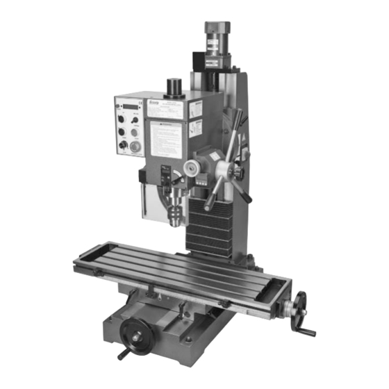
INTRODUCTION Manual Accuracy Contact Info your machine may not exactly match the manual Machine Description www.grizzly.com... - Page 5 Identification Figure 1.
- Page 6 MACHINE DATA SHEET MODEL G0720 HEAVY-DUTY BENCHTOP MILLING MACHINE...
-
Page 8: Section 1: Safety
SECTION 1: SAFETY For Your Own Safety, Read Instruction Manual Before Operating this Machine The purpose of safety symbols is to attract your attention to possible hazardous conditions. This manual uses a series of symbols and signal words intended to convey the level of impor- tance of the safety messages. - Page 9 DISCONNECTING POWER SUPPLY. FORCING MACHINERY. GUARDS & COVERS. APPROVED OPERATION. NEVER STAND ON MACHINE. STABLE MACHINE. DANGEROUS ENVIRONMENTS. AWKWARD POSITIONS. ONLY USE AS INTENDED. USE RECOMMENDED ACCESSORIES. UNATTENDED OPERATION. CHILDREN & BYSTANDERS. MAINTAIN WITH CARE. REMOVE ADJUSTING TOOLS. CHECK DAMAGED PARTS. SECURING WORKPIECE.
- Page 10 Additional Safety for Mills UNDERSTANDING CONTROLS. MACHINE CARE AND MAINTENANCE. SAFETY ACCESSORIES. WORK HOLDING. DISCONNECT POWER. CHUCK KEY SAFETY AVOIDING ENTANGLEMENT SPINDLE SPEEDS. BE ATTENTIVE. POWER DISRUPTION. TOOL HOLDING. STOPPING SPINDLE. CLEAN-UP. CUTTING TOOL INSPECTION. EXPERIENCING DIFFICULTIES. No list of safety guidelines can be complete. Like all machinery there is potential danger when operating this machine.
-
Page 11: Section 2: Power Supply
SECTION 2: POWER SUPPLY Availability Circuit Requirements Nominal Voltage ....... 110V/120V Cycle ............60 Hz Phase ........... Single-Phase Minimum Circuit Size ......20 Amps Electrocution, fire, equipment damage may occur if machine is not correctly grounded and connected to the power supply. - Page 12 Grounding & Plug Requirements Serious injury could occur if you connect Extension Cords the machine to power before completing the setup process. DO NOT connect to power until instructed later in this manual. GROUNDED 5-15 RECEPTACLE 5-15 PLUG Figure 2. Minimum Gauge Size ......12 AWG Maximum Length (Shorter is Better)..50 ft.
-
Page 13: Section 3: Setup
SECTION 3: SETUP Needed for Setup This machine presents serious injury hazards to untrained users. Read through this entire manu- al to become familiar with Description the controls and opera- tions before starting the machine! Wear safety goggles dur- ing the entire setup pro- cess! Unpacking This machine and its com-... - Page 14 Inventory Box 1: (Figures 3 & 4) Figure 4. NOTICE If you cannot find an item on this list, check the mounting location on the machine or the packaging materials. Sometimes parts are pre-installed for shipping, or they become hidden by packaging materials. Figure 3.
- Page 15 Cleanup Gasoline or products with low flash points can explode or cause fire if used to clean machin- ery. Avoid cleaning with these products. Many cleaning solvents are toxic if concentrat- ed amounts are inhaled. Only work in a well-venti- lated area.
- Page 16 Site Considerations Weight Load Physical Environment Machine Data Sheet Space Allocation Electrical Installation See below for required space allocation. Lighting Children or untrained people may be seriously injured by this machine. Only install in an access restricted location. Figure 6.
- Page 17 Mounting to Test Run Workbench Components and Hardware Needed: Troubleshooting Page 34 To mount the mill to the workbench: Note: For the best performance, make Before starting the machine, make sure you sure the cross feed and the longitudinal have performed the preceding assembly handwheels extend out beyond the edge of and adjustment instructions.
- Page 18 Lubrication SECTION 6: MAINTENANCE Page 30. Note: The drawbar cap has left-hand threads and loosens when turned clockwise. Spindle Break-In Figure 8 NOTICE Figure 8 Failure to follow start up and spindle break- in procedures will likely cause rapid dete- rioration of spindle and other related parts.
- Page 19 Spindle Break-In Note: When in tapping mode, the spin- dle speed is reduced by half automatically, and the speed range will be 50–800 RPM. Test Run Tapping requires lower speeds than other milling operations. DO NOT leave the area while break-in pro- cedure is under way.
-
Page 20: Section 4: Operations
WE STRONGLY REC- OMMEND that you read books, review industry trade magazines, or get formal training before beginning any projects. Regardless of the content in this section, Grizzly Industrial will not be held liable for accidents caused by lack of training. - Page 21 C. Main Power Switch: Controls D. Downfeed Handle: E. Handwheels: General Controls Figure 10 Control Panel Figure 11 Figure 11. POWER Lamp: G. UP/DOWN Buttons: H. RPM Dial: Spindle Speed Readout: Figure 10. MILLING & TAPPING Switch: A. Fine Feed knob: K.
- Page 22 Digital Spindle Height Gauge Mini Digital Protractor Figure Figure 13 Figure 12. Figure 13. M. Digital Spindle Height Display: Q. Tilt Arrows: R. Battery Life: N. ZERO Button: S. ON/OFF Button: O. mm/inch Button: OFF/ON Button: U. Calibrate: HOLD:...
- Page 23 Selecting Spindle Setting Spindle Height Figure 15 To change the spindle position: To determine the needed RPM: Figure 14 Tip: Use the fold-out lever ( Figure 15) for additional leverage to unlock the fine feed lock knob if the knob is too tight. Do not use the fold-out lever to tighten the knob.
- Page 24 Drill Chuck Installation & Removal Installation Figure 16. NOTICE DO NOT completely unscrew the drawbar before tapping it with the hammer in the next Step. You will damage the threads on the drawbar and the arbor. Note: Do not overtighten the drawbar. Overtightening makes arbor removal difficult and will damage the arbor and threads.
- Page 25 Removal R-8 Collet Installation & Removal LACERATION HAZARD! Leading edges of end mills and other cutting tools can be very sharp. Protect your hands with gloves or a shop towel when handling. Installation NOTICE DO NOT completely unscrew the drawbar before tapping it with the hammer in the next Step.
- Page 26 Headstock Travel Figure 20 (Z-Axis & Rotation) Note: When the headstock reaches a point of travel where the leadscrew has run out of thread, a stop block (see Figure 20) contacts either the upper or lower limit switch to stop the elevation motor from over running the physical limitations of the leadscrew length, which would cause damage.
- Page 27 Tilting Figure 22 Figure 21 CALIBRATE Note: The spring-loaded index pin serves only as a quick way to return or position the headstock close to zero, or 45 to the left or right. It is not intended to be an exact angle stop.
- Page 28 Table Travel (X-Axis & Y-Axis) Figure 23. X-Axis Figure 24 Figure 25 Figure 24. Y-Axis Figure 25 Figure 25.
- Page 29 Milling/Drilling Mode Tapping Mode Overloading the bit, tap, or cutter or using excessive spindle speeds may threaten operator safety from ejected parts or bro- ken tools Overloading the bit, tap, or cutter or using excessive spindle speeds may threaten To mill a workpiece: operator safety from ejected parts or bro- ken tools Controls...
-
Page 30: Section 5: Accessories
Grizzly. Note: To use this tapping attachment on the NOTICE Model G0720 mill, you must purchase the G1427 R-8/ MT #2 Morse Taper sleeve. Refer to the newest copy of the Grizzly Catalog for other accessories available for this machine. - Page 31 G9760—20-PC. 2 & 4 Flute TiN End Mill Set. G5641—1-2-3 Blocks G9815—Parallel Set Figure 29. Figure 32. G9765—9-PC. Ball End Mill Set G9324—Boring Head Combo Set Figure 30. H3022—Measurement Tool Set Figure 33. Figure 31.
-
Page 32: Section 6: Maintenance
SECTION 6: MAINTENANCE Monthly Always disconnect power to the machine before performing maintenance. Annually Failure to do this may result in serious person- al injury. Schedule Lubrication Ongoing Figure Daily, Before Operations Daily, After Operations Figure 34. - Page 33 Ball Oilers Figures 35 39 Figure 37 Items Needed: Figure 38 Figure 35 Figure 39 Figure 36...
- Page 34 Leadscrews Items Needed: Figure 40 To lubricate the leadscrews: Figure 41 Figure 40 Figure 41.
- Page 35 Digital Spindle Height Gauge Battery Replacement Items Needed: To replace the battery: Figure 43 Figure Figure 43. Mini Digital Protractor Items Needed: To replace the batteries: Figure 44 Figure 42. Figure 44.
-
Page 36: Section 7: Service
SECTION 7: SERVICE Troubleshooting... - Page 37 Gib Adjustment NOTICE When adjusting gibs, keep in mind that the goal of gib adjustment is to remove unnec- essary sloppiness from the slide without causing binding and excessive leadscrew nut wear. Figure 45 Table Gib Adjustment Figure 45 Figure 45.
- Page 38 Headstock Gib Adjustment Machine Storage Figure 46. To prepare your machine for storage: Figure 46. Figure...
-
Page 39: Section 8: Wiring
WIRE CONNECTIONS. CIRCUIT REQUIREMENTS. EXPERIENCING DIFFICULTIES. The photos and diagrams included in this section are best viewed in color. You can view these pages in color at www.grizzly.com. READ ELECTRICAL SAFETY READ ELECTRICAL SAFETY ON THIS PAGE! ON PAGE 37! - Page 40 Wiring Overview Component Locations Page 39 Figure 54 Page 40 Figure 54 Page 40 Figure 52 Page 40 Figure 51 Page 40 Figure 49 Page 40 Figure 50 Page 39 Figure 48 Page 39 Figure 47 Page 39 Figure 49 Page 39 Figure 49 System...
- Page 41 Wiring Diagram MAIN POWER SWITCH (both sides shown) Elevation Motor Elevation Travel Limit Switches To Control Panel (see Page 40) 110 VAC 5-15 Plug (As Recommended) READ ELECTRICAL SAFETY ON PAGE 37!
- Page 42 Wiring Diagram Digital Spindle Mini Digital Spindle Depth Unit Protractor Motor CONTROL PANEL (Viewed from behind) Electrical Panel (see Page 39) Chip Guard Spindle Safety Switch Direction Switch Halogen Work Lamp READ ELECTRICAL SAFETY ON PAGE 37!
- Page 43 Electrical Components Figure 48. Figure 47. Figure 49. READ ELECTRICAL SAFETY ON PAGE 37!
- Page 44 Figure 53. Figure 50. Figure 51. Figure 52. Figure 54. READ ELECTRICAL SAFETY ON PAGE 37!
-
Page 45: Section 9: Parts
SECTION 9: PARTS Head Breakdown... - Page 46 Head Parts List REF PART # DESCRIPTION REF PART # DESCRIPTION P0720001 DRAWBAR COVER P0720046 COMPRESSION SPRING 0.8 X 10 X 14 PCAP24M CAP SCREW M5-.8 X 16 P0720047 FLANGE PLASTIC P0720003 FLANGE PS59M PHLP HD SCR M3-.5 X 14 PCAP49M CAP SCREW M6-1 X 60 PS74M...
- Page 47 Head Parts List REF PART # DESCRIPTION REF PART # DESCRIPTION PS79M PHLP HD SCR M3-.5 X 8 120 PSTB005M STEEL BALL 10MM P0720092 HEAD FRONT COVER 121 PS74M PHLP HD SCR M4-.7 X 14 PS13M PHLP HD SCR M3-.5 X 20 122 P0720122 GEAR FLANGE P0720094 LOCK SCREW 123 P0720123 WORM GEAR...
- Page 48 Column Breakdown...
- Page 49 Column Parts List REF PART # DESCRIPTION REF PART # DESCRIPTION PS76M PHLP HD SCR M8-1.25 X 12 P0720236 STRAIN RELIEF LT PLW04M LOCK WASHER 8MM PW08M FLAT WASHER 16MM PW01M FLAT WASHER 8MM P0720238 TAPER PIN 10 X 45 204A P0720204A LEADSCREW W/NUT ASSEMBLY PCAP192M CAP SCREW M16-2 X 55 P0720204A ELEVATION LEADSCREW...
- Page 50 Table Breakdown...
- Page 51 Table Parts List REF PART # DESCRIPTION REF PART # DESCRIPTION PS08M PHLP HD SCR M5-.8 X 12 PK37M KEY 4 X 4 X 16 P0720302 CROSS WAY COVER PW01M FLAT WASHER 8MM PLUBE002M TAP-IN BALL OILER 8MM PLW04M LOCK WASHER 8MM P0720305 GIB SCREW PCAP58M...
- Page 52 MUST maintain the original location and readability of the labels on the machine. If any label is removed or becomes unreadable, REPLACE that label before using the machine again. Contact Grizzly at (800) 523-4777 or www.grizzly.com to order new labels.
- Page 53 WARRANTY CARD The following information is given on a voluntary basis. It will be used for marketing purposes to help us develop better products and services. Of course, all information is strictly confidential. Note: We never use names more than 3 times. _____________________________________________________________________ _________________________________________________________________________________ _________________________________________________________________________________...
-
Page 55: Warranty And Returns
WARRANTY AND RETURNS 1 year... - Page 56 ® Buy Direct and Save with Grizzly – Trusted, Proven and a Great Value! ~Since 1983~ Visit Our Website Today For Current Specials! ORDER 24 HOURS A DAY! 1-800-523-4777...
Need help?
Do you have a question about the G0720 and is the answer not in the manual?
Questions and answers