Table of Contents
Advertisement
Quick Links
Advertisement
Table of Contents

Subscribe to Our Youtube Channel
Related Manuals for ADDER AdderView Matrix


Summary of Contents for ADDER AdderView Matrix
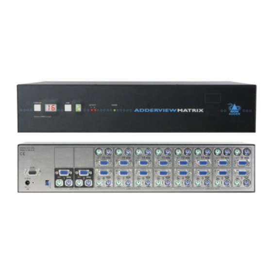
- Page 1 AdderView Matrix User Guide ...
-
Page 2: Table Of Contents
Creating power port groups..........27 How cascade connections operate........13 Logging access activity ............28 Addressing computers in a cascade ........14 Display Data Channel (DDC)..........28 Using cascaded computers..........15 Adder Port Direct..............29 Testing specific links to cascaded computers....15 Multiple video head connections ........16 Contents - page 2... - Page 3 RS232 serial mouse to PS/2 converter cable ....45 RS232 serial flash upgrade cable........45 RS232 serial synchronisation cable........45 AdderView Matrix to power switch cable .....46 Power switch to power switch daisy chain cable ...46 AdderView Matrix setup cable ........46 Other products in the Adder range..........47 Safety information ..............47...
-
Page 4: Welcome
Introduction sets. Alternatively, an AdderLink IP can be connected instead to Thank you for choosing the AdderView Matrix from provide remote control options. Adder Technology. This advanced switch (available in two sizes) allows you to control multiple host computers directly, or far more computers in combination with other similar switches. -
Page 5: What's In The Box
Master power switch for connection to AdderView Matrix or standalone Ethernet operation (part number: PSU-8MASTER) CD-ROM Slave power switches for connection to AdderView Matrix or master power switch (part number: PSU-8SLAVE) PS/2 to AT-style keyboard converter (part number: VSA3) PS/2 to 9-pin serial mouse converter... -
Page 6: Installation
• Power supply connection The AdderView Matrix can be used on a desktop or mounted within a 19” rack. There are also connections that can be made to achieve more advanced For desktop applications, attach the supplied self-adhesive feet to the underside configurations: to avoid damage to the desktop surface. -
Page 7: User Port Connections
User port connections Computer port connections to standard computers There are two user ports available at the rear of the AdderView Matrix. Each AdderView Matrix can be directly connected to a maximum of either eight port consists of three sockets to accommodate: a keyboard, a video monitor and (model AVM208) or sixteen (model AVM216) computer systems. -
Page 8: Computer Port Connections To Alternative Computers
2, 5 or 10 metres) allows Sun computers to be connected to the AdderView Matrix. To connect a Sun computer 1 Ensure that power is disconnected from the AdderView Matrix and the Sun computer to be connected. 2 At the end of the converter cable that has three plugs, connect the... -
Page 9: Connections To A Usb Port
AdderView Matrix. To connect a USB port computer Keypress equivalents 1 Ensure that power is disconnected from the AdderView Matrix and the The tables given here provide equivalent keypresses on a standard PC (PS/2- computer to be connected. -
Page 10: Power Supply Connection
Power supply connection The AdderView Matrix is supplied with a single power supply and an appropriate country-specific IEC power lead. The AdderView Matrix does not have an on/off switch so operation begins as soon as the power supply is connected. -
Page 11: Adderlink Ip Connections
7 Connect the IEC connector of the supplied country-specific power lead to sockets, of either of the two USER PORTS, at the rear of the AdderView Matrix. the socket of the power supply. Connect the power lead to a nearby main supply socket. -
Page 12: Power Switching Connections
Power switching connections To connect and address the switch boxes A key feature of the AdderView Matrix is its ability to remotely control the Note: The AdderView Matrix can be powered on during this procedure, power of the computers attached to it. The actual power switching process however, the switch boxes should be switched off. -
Page 13: Cascade Connections
Cascade connections The AdderView Matrix supports up to eight (model AVM208) or sixteen (model AVM216) directly connected computer systems, however, this is U se r U se r by no means the limit. Thanks to an intelligent communication system, called... -
Page 14: How Cascade Connections Operate
This is due to the Adder Port Direct communication system employed by most Adder switching products that allows them to locate each other and share information. The method of linking switches is the same regardless of the cascade level, or number of devices attached. -
Page 15: Addressing Computers In A Cascade
The group at level 2 is numbered 23 because it is a group of two, connected to 21 23 27 02 21 04 ports 5 and 6 on the AdderView Matrix. If it was connected to ports 7 and 8, then the group number would be 24. U se r... -
Page 16: Using Cascaded Computers
Configuration chapter for more details. When using the AdderLink IP in conjunction with the AdderView Matrix it may Tips for successful cascading be necessary to change the standard hotkeys for one of the devices as they both as their standard hotkeys. -
Page 17: Multiple Video Head Connections
Ensuring that the serial port is available Two or more AdderView Matrix units can be connected together so that The AdderView Matrix has a single RS232 COM port which is used to send/ they operate in a synchronised manner. Synchronised operation is useful for receive configuration data, control power switches and synchronise multiple applications that require multiple video signals to be switched together. -
Page 18: Configuration
• Unless a locally connected user is required to access timing characteristics. the computers, you do not need to configure Setup After all of the above steps are completed, the AdderView Matrix should be fully Options or Global Preferences, skip step 5. configured. -
Page 19: Configuration Menus
• Set individual and global settings for users, when following the instructions in this guide. • Run various functions, such as mouse restore operation, • Save and load AdderView Matrix configuration settings, and more. To access the Configuration menu Security... -
Page 20: Configuration Menus Layout
Keypad Controls To change the hotkeys Exclusive Use When using the AdderLink IP in conjunction with the AdderView Matrix it will Automatic Logout be necessary to change the standard hotkeys for one of the devices. They both as their standard hotkeys, so only the first one in the chain Edit Computer List (usually the AdderLink IP) will respond to your requests. -
Page 21: Registering Users
Note: The Adder Port Direct feature (which allows interconnected Adder 5 Press to display the ‘Edit Access Rights’ menu. Here you can determine KVM switches to talk to one another) ensures that users without access... -
Page 22: Autoscanning
• All PCs – This mode visits, in turn, each computer that is connected directly each computer is displayed, ranging from 2 seconds to 5 minutes. to the AdderView Matrix. This mode should be used with care due to the To define an autoscan list reasons given in the warning below. -
Page 23: Saving And Restoring Configuration Settings
Saving and restoring configuration settings The AdderView Matrix can store up to 512 computer names and 16 sets of To edit the configuration settings user access rights. Particularly in cascaded configurations, manually re-entering The saved XPRODATA.CSV file can be opened using a spreadsheet program such all computer names, port numbers and access rights can be a lengthy process. -
Page 24: What To Do If The Admin Password Has Been Forgotten
1 Power on the AdderView Matrix normally. 2 The ‘Functions’ option should be highlighted, press 2 Whilst the AdderView Matrix is powered on move switch 2 on the rear panel of the AdderView Matrix (labelled UPGRADE) to the ON (down) position. -
Page 25: Hot Plugging And Mouse Restoration
To restore mouse operation when hot plugging: It is strongly recommended that you switch off a computer before attempting to connect it to the AdderView Matrix. However, if this is not possible then you 1 Using a KVM cable set, carefully make the connections between the keyboard, monitor and mouse sockets of the computer and the required need to ‘hot plug’... -
Page 26: Resetting User Port Keyboards And Mice
Note: If a remote computer has mouse acceleration enabled and you need to 1 Press the USER key on the front panel of the AdderView Matrix to select the disable it remotely, then it can be difficult to accurately position the remote user port whose keyboard and mouse you wish to reset. -
Page 27: Power Switching Configuration
Power switching configuration Power switch configuration comprises three main steps: • Configure the serial port to the same settings used by the power switch boxes. • Configure a power ON string for each power port. • Configure a power OFF string for each port. The procedures used to achieve the latter two steps are almost identical. -
Page 28: Editing Power Strings
- other power switches may require different settings. Please four ports can be formed into a power port group. refer to Adder for advice on how to configure the AdderView Matrix to control To add/edit further power strings in order to switch extra ports other power switches. -
Page 29: Logging Access Activity
Technology website. 15” VGA monitor on user port 1 and a 17” multiscan monitor on user port 2. In such cases, it is important to ensure that the AdderView Matrix samples the 2 Follow the instructions in the section Saving and restoring configuration lower specified of the two monitors. -
Page 30: Adder Port Direct
This is termed ‘sideways movement’ and is thwarted by the Adder Port Direct feature because each unit is fully informed of each user’s precise access rights. -
Page 31: Powering On
Operation Powering on The AdderView Matrix does not have a power switch, so whenever power is applied via the supplied adapter, the unit is operational. A green indicator on the front panel (labelled ‘Power’) shows power input status. Note: Before applying power to the AdderView Matrix, ensure that the two option switches at the rear panel are both set to the OFF (up) position. -
Page 32: Using The Adderview Matrix
Using the AdderView Matrix Selecting a computer Note: When the AdderView Matrix is used in conjunction with an AdderLink IP To select a computer using the on-screen menu (and security is enabled), the AdderView Matrix will automatically enter a slave 1 Select the on-screen menu in one of three ways: mode. - Page 33 To awaken the monitor, simply select ‘hotkeys’ and they signal to the AdderView Matrix that you wish to control any fixed channel using any of the suggested it, rather than the computer. However, if these particular hotkeys clash with methods.
-
Page 34: Logging In And Out
Logging in and out 1 Select the on-screen menu by pressing the middle and right buttons of a The AdderView Matrix features a straightforward security system that helps to three button mouse. prevent unauthorised access to some, or all connected computers. -
Page 35: Selecting Cascaded Computers
Selecting cascaded computers The reminder banner The AdderView Matrix is not limited to sharing just sixteen (or eight) computers. As many computer screen layouts can appear very similar, the AdderView Matrix By joining numerous AdderView Matrix products together in a tree-like or... -
Page 36: Routing Status
‘Exclusive’ access. For this purpose the AdderView Matrix provides reset computers that are failing to respond. -
Page 37: Further Information
Poor video quality with smearing, fuzziness or ripple If you are still experiencing problems after checking the list of solutions in the • Use coaxial video cables to connect your devices to the AdderView Matrix. Troubleshooting section then we provide a number of other solutions: When power switching, the selected computer does not power on or off •... -
Page 38: Appendices
-Down Esc-Quit Settings: ENABLED, DISABLED The key controls on the front of the AdderView Matrix may be disabled so that it is only possible to select the special channels “o” and “0” (the on-screen menu and the non-existent channel zero). -
Page 39: Global Preferences
2 Press to select ‘More menus’. ADDERVIEW MATRIX with exclusive use. The AdderView Matrix has the facility to allow users to select 3 Highlight ‘Global Preferences’ and press Global Preferences exclusive use of computers but this facility should be used with care. When... - Page 40 When two users are connected to the same computer only one can have access Matrixs. If you wish to scan the ports on the current AdderView Matrix then at any one time. When no keyboard or mouse data has been received from the...
-
Page 41: User Preferences
3 Highlight ‘User Preferences’ and press 4 Use the following keys: Reminder Colour ADDERVIEW MATRIX to highlight required options. Settings: BLUE/TRANS, PINK/TRANS, BLUE/WHITE, WHITE/RED User Preferences to change option values. You may select the colour of the reminder banner. The BLUE/TRANS and PINK/... - Page 42 This option is used to save AdderView Matrix configuration information to a specially connected computer. A temporary link must be made using the serial port at the rear of the AdderView Matrix and the computer must run a custom Enter-Run Function routine available from www.adder.com.
-
Page 43: Advanced Options
When enabled, the RS232 COM port can be used only to send commands to When enabled, the AdderView Matrix can discover the capabilities of a user port optional power control modules connected to it. When disabled, it may be used... -
Page 44: Appendix 2 - Firmware Upgrade
Connect the serial port of the computer to the port marked COM on the • Optional serial upgrade cable available from Adder (p/n: CAB-9M/9F-2M) rear panel of the AdderView Matrix. You do not need to set the serial baud (see Appendix 3 for pin-out specifications). - Page 45 7 - Switch the UPGRADE key to the OFF position and cycle the power Switch the switch 2 on the rear of the AdderView Matrix to the OFF position and disconnect the power. When the power is re-applied the AdderView...
-
Page 46: Appendix 3 - Cable And Connector Specifications
MASTER end SLAVE end female female 9pin D-type male 9pin D-type male Use this cable when two AdderView Matrix devices are being synchronised. MASTER end SLAVE1 end 9pin D-type male 9pin D-type male Use this cable when three AdderView Matrix devices are being synchronised. -
Page 47: Adderview Matrix To Power Switch Cable
AdderView Matrix setup cable 9pin D-type female 9pin D-type female AdderView Matrix to power switch cable 9pin D-type female 4pin RJ9 Power switch to power switch daisy chain cable 4pin RJ9 4pin RJ9... -
Page 48: Other Products In The Adder Range
• AdderLink Gold receiver (part code: ALGRX) • If you use a power extension cord with the AdderView Matrix, make sure • AdderLink Silver receiver (part code: ALSRX) the total ampere rating of the devices plugged into the extension cord does •... -
Page 49: Radio Frequency Energy
Radio Frequency Energy A Category 5 (or better) twisted pair cable must be used to connect the AdderLink units in order to maintain compliance with radio frequency energy emission regulations and ensure a suitably high level of immunity to electromagnetic disturbances. All other interface cables used with this equipment must be shielded in order to maintain compliance with radio frequency energy emission regulations and ensure a suitably high level of immunity to electromagnetic disturbances. - Page 50 © 2006 Adder Technology Limited All trademarks are acknowledged. Release 1.1e January 2006 Part No. ADD0061 Adder Corporation, Adder Technology Limited, 29 Water Street, Technology House, Newburyport, Trafalgar Way, Cambridge, CB3 8SQ, MA 01950, United Kingdom United States of America...
-
Page 51: Index
31 Sun computer 7,8 AdderLink IP forgotten 23 Configuration connections 10 Port Direct 29 power switching 26 Adder Port Direct 29 Powering on 30 codes for switching 27 saving and restoring 22 Testing Addressing Power control Hotkey Configuration menus 37...
Need help?
Do you have a question about the AdderView Matrix and is the answer not in the manual?
Questions and answers