
Related Manuals for Campbell DCP-Intelimax


Summary of Contents for Campbell DCP-Intelimax
- Page 1 DCP-Intelimax Modem Kit Revision: 05/15 C o p y r i g h t © 0 0 0 0 - 0 0 0 0 C a m p b e l l S c i e n t i f i c ,...
-
Page 2: Table Of Contents
Table of Contents Table of Contents PDF viewers: These page numbers refer to the printed version of this document. Use the PDF reader bookmarks tab for links to specific sections. 1. Introduction ..............1 2. Getting Started ............1 3. Network Coverage ............1 4. - Page 3 9.4.1 Configuring Logger for RS-232 over Control Ports ....20 Connection via RS232 port ..............22 Connection via CPI Port ..............23 10. Power Considerations ..........23 10.1 Current Requirements ................ 23 10.2 Switched Power ................. 24 10.2.1 SW12 and Remote Program Upload ........... 24 11.
- Page 4 Table of Contents FIGURE 9-4. Modem connection to data logger control port ...... 19 FIGURE 9-5. Connecting with Device Configuration Utility ....... 20 FIGURE 9-6. ComPorts Settings ..............21 FIGURE 9-7. Modem connection to data logger RS232 port ...... 22 FIGURE 9-8 CR6 Data Logger ..............
-
Page 5: Introduction
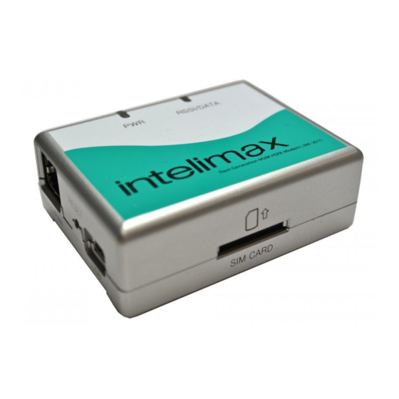
DCP-Intelimax Digital Cell Phone Kit Introduction The DCP-Intelimax Digital Cell Phone Kit is Campbell Scientific Australia’s industrial cell phone kit for use with 2G and 3G networks. Suitable for use throughout Australia and capable of automatically detecting local communications frequencies and accepting an appropriate local SIM across the world. -
Page 6: Specifications
Appendix Title Though this manual focuses on use of the Intelimax modem kit with Telstra’s NextG service, the Intelimax is compatible with all 3G and GSM frequency bands including those used by Optus, Vodafone and their resellers. Coverage maps are available from the service providers. Please note however that even though an area is shown as covered on the map, it is important to check the signal strength on site. -
Page 7: Circuit Switched Data
If the unit is set up with a security code or PIN number, it should be disabled before use with the Campbell Scientific data logger. The security code or PIN number can be disabled by putting the SIM card into a normal digital mobile phone and select the security menu. -
Page 8: Modem Overview
Appendix Title Some users may have experienced reliability problems when calling a NextG modem on the Telstra network from a non-Telstra telephone line. Please see Troubleshooting for more information. Modem Overview The Intelimax modem is a powerful communications product which employs a quad-band HSUPA/HSDPA/WCDMA/GPRS/EDGE modem module (HUAWEI EM820) with an internal ARM9 processor. -
Page 9: Operation Modes
PPP WAN modes, as shipped from Campbell Scientific Australia, the modem is configured for use as a normal serial modem. PPP WAN mode is not supported by Campbell Scientific Australia at this time. Serial Modem In this mode, the Intelimax’s extra features are disabled and the modem acts as any other serial modem. -
Page 10: Modem Configuration
AT commands to the modem and by using the modem’s configuration software (the GUI). Modems purchased from Campbell Scientific Australia will be pre-configured with the correct settings to interface with our CR800, CR1000, CR3000 and CR6 data loggers. Some configuration will be necessary for correct use with our CR200X, CR510X, CR10X and CR23X loggers. -
Page 11: Figure 8-1. Usb Network Interface
When installing on Windows 7 or later, the drivers should install automatically when the modem is connected to a PC via USB. When connecting the modem to the GUI, the mini USB must be connected as well as the serial cable to provide power. Use of the GUI requires both serial power and USB –... -
Page 12: Figure 8-2. Connection Properties
Appendix Title The following window will appear. FIGURE 8-2. Connection properties Select Internet Protocol Version 4 (TCP/IPv4) and click Properties. -
Page 13: Intelimax Gui
FIGURE 8-3. IPv4 Settings Fill out the details for the connection as above and select OK. The connection is now properly configured. The Intelimax manual (available from http://www.maxon.com.au) describes the process to connect to the modem using the GUI in the section titled “Connecting to the Intelimax”. -
Page 14: Configuring The Modem For Serial Modem Operation
Appendix Title Connect both power and USB to the modem. Start the GUI software. If the USB drivers are properly installed and configured, “Device found” will appear in the Ouptut Info window. Although some limited functions are available via a serial connection, USB is strongly recommended. -
Page 15: Configuring The Modem For Ip Stack Operation
The Intelimax may be configured using the GUI. AT commands are not typically required in configuration, operation or troubleshooting. Campbell Scientific Australia offers professional training courses on a broad range of topics related to data logging, measurement and communications. Our Communications training course provides hands-on training in the use of many communications peripherals, including the use of AT commands with modems. -
Page 16: Data Logger Connection
Section 2 of your Communications training manual. Data Logger Connection Different models of Campbell Scientific data loggers have a CS I/O port and/or RS232 communication port(s). The Intelimax can be connected to either port. However, the hardware configuration for connection to each port differs. -
Page 17: Datalogger I/O Ports For Modem Connection
Retired CR9000 Retired CR200(X) Active Y(9600 baud) CR800 Active Series CR1000 Active CR3000 Active CR5000 Retired CR9000X Active Active Requires 31056 adaptor Note: All Campbell Scientific data loggers have control ports however older models cannot use them for RS-232 connection. -
Page 18: Connection Via Cs I/O Ports
Appendix Title Connection via CS I/O Ports FIGURE 9-1. Modem connection to data logger CS I/O port TABLE 9-2. Parts Supplied with CS I/O Modem Kit Part number Description 14162 Enclosure mounting kit for modem CSIO-INTELIMAX-CBL DCE RS-232 female to RJ45 cable MA-2015 Intelimax modem SC932A... -
Page 19: Sc105 Interface
In order for the SC105 to work effectively with the Intelimax modem, the SC105 default settings will need to be slightly modified. To change these settings, we recommend using Campbell Scientific’s Device Configuration Utility, available from https://www.campbellsci.com/downloads. If desired, configuration changes can also be made using a terminal emulator package and... -
Page 20: Sc1105 Configuration Using Device Configuration Utility
Appendix Title 9.3.2 SC1105 Configuration using Device Configuration Utility FIGURE 9-2. SC105 connection via Device Configuration Utility... -
Page 21: Figure 9-3. Sc105 Deployment Configuration
To configure the SC105 using Device Configuration Utility, first connect the female-female null modem cable supplied with the SC105 to your PC’s serial port and the Modem connector on the SC105. Next, provide power to the SC105 by connecting the SC12 cable supplied to the SC105’s Datalogger connector and the CS I/O port of a datalogger. -
Page 22: Configuring The Sc105 Using Hyperterminal
Settings Editor Tab. Change the RS-232 Auto Power Down setting to “RS-232 Always Active to power RS-232 devices” and click Apply again. Your SC105 is now configured for use with a DCP-INTELIMAX-CSIO modem kit. 9.3.3 Configuring the SC105 using Hyperterminal... -
Page 23: Connection Via Control Ports
Connection via Control Ports FIGURE 9-4. Modem connection to data logger control port TABLE 9-4. Parts Supplied with CPORT Modem Kit Part number Description 14162 Enclosure mounting kit for modem CPORT-INTELIMAX-CBL Control port to RJ45 cable MA-2015 Intelimax modem ANT-ADAPTER-INTELIMAX FME to SMA adaptor To connect a new control port modem kit to a data logger, follow these steps: Connect the CPORT-INTELIMAX-CBL’s RJ45 connector to the socket on the modem. -
Page 24: Configuring Logger For Rs-232 Over Control Ports
Appendix Title Connect the black and red wires on this cable to the data logger. The red wire connects to 12V and the black wire to the G terminal. The SW12 terminal can be used instead of 12V however as it is a switched supply it needs to be enabled in the datalogger program to function correctly. - Page 25 FIGURE 9-6. ComPorts Settings To complete configuring the logger for RS-232 over the control ports: Go to the ComPorts Settings tab. Select the COM port that you have wired the modem into. Click Apply.
-
Page 26: Connection Via Rs232 Port
Appendix Title Connection via RS232 port FIGURE 9-7. Modem connection to data logger RS232 port TABLE 9-5. Parts Supplied with RS232 Modem Kit Part number Description 14162 Enclosure mounting kit for modem RS232-INTELIMAX-CBL DTE RS-232 male to RJ45 cable MA-2015 Intelimax modem ANT-ADAPTER-INTELIMAX FME to SMA adaptor... -
Page 27: Connection Via Cpi Port
FIGURE 9-8 CR6 Data Logger With the addition of a 31056 CPI-RS-232 adaptor, connection of the CR6 to the DCP-INTELIMAX-RS232 is identical to that described in Section 9.5 with the 31056 adapator serving as the RS-232 port. 10. Power Considerations 10.1 Current Requirements... -
Page 28: Switched Power
Appendix Title Use the current consumption numbers in the Specifications section to calculate the power consumption of your modem and the size of battery, solar panel and charging regulator that you will require. 10.2 Switched Power In order to reduce the current consumption of the modem, power to the modem can be switched on and off at different times or under certain circumstances by utilizing the Switched 12V supply or by using an external relay circuit. -
Page 29: Antenna And Surge Protection
1.75dB. An external antenna is a risk to sensitive electronics within an enclosure if a lightning strike hits the station. Campbell Scientific Australia has a surge protector available suitable for bulkhead mounting with an FME to N-Type... -
Page 30: Serial Vs Tcp/Ip
The Intelimax modem is capable of sending and receiving SMS messages in two modes: Serial Modem mode and PPP WAN mode. PPP WAN mode is not supported by Campbell Scientific Australia at this time. 12.1.1 Serial Modem Mode In Serial Modem mode, the modem acts as any other Hayes modem and can send or receive Circuit Switched Data (CSD) calls. - Page 31 ' This program demonstrates how to use the CR1000 serial instructions to send an SMS ' using a Intelimax modem ' === WIRING ========================================================================== ' ComRS232 Intelimax ' 1H Thermocouple +, (red stripe) ' 1L Thermocouple -, (blue wire) ' === DECLARATIONS ==================================================================== ' -- Constants ------------------------------------------------------------------------ Const COMPORT = ComME ' Comport Used for Serial I/O...
-
Page 32: Advanced Communications
For more information including costs and course schedules, see https://www.campbellsci.com.au/training. 14. Troubleshooting Campbell Scientific Australia’s modem kits are designed to for ease of use and simplicity. Even so, there are sometimes issues when installing, especially for the first time. -
Page 33: Power
14.1.6 Baud Rate The default for the modem is to communicate at 115200 to any device. For some Campbell Scientific data loggers, such as the Array-Based data loggers, the maximum baud rate is 9600. Please check the data logger manual for... -
Page 34: Sim Pin
Bearer Code 2620 – see Section 3. This is the number that the modem must be called on. If you have difficulty getting a data number activated on your SIM, contact Campbell Scientific. - Page 35 • info@campbellsci.com.cn • info@campbellsci.de www.campbellsci.com www.campbellsci.de Campbell Scientific do Brasil Ltda. (CSB) Campbell Scientific Spain, S. L. (CSL Spain) Rua Apinagés, nbr. 2018 ─ Perdizes Avda. Pompeu Fabra 7-9, local 1 CEP: 01258-00 ─ São Paulo ─ SP 08024 Barcelona...
Need help?
Do you have a question about the DCP-Intelimax and is the answer not in the manual?
Questions and answers