Garmin TR-1 GOLD 906-2000-00 Owner's Manual
Garmin fish finder - electronic fish finder user manual
Hide thumbs
Also See for TR-1 GOLD 906-2000-00:
- Basic operation manual (9 pages) ,
- Mounting instructions (7 pages) ,
- Installation instructions (4 pages)
Table of Contents
Advertisement
Advertisement
Table of Contents

Related Manuals for Garmin TR-1 GOLD 906-2000-00


Summary of Contents for Garmin TR-1 GOLD 906-2000-00
- Page 1 TR-1 Gold Owner’s Manual 906-2000-00 RevH 101507...
-
Page 2: Table Of Contents
Your purchase of this TR-1 Gold outboard management system enters you in the prestigious fraternity of anglers who count on TR-1 to control their outboard kickers. TR-1 Autopilots is dedicated to creating the finest controls and guidance systems for the best in boating and fishing. -
Page 3: Safety & Cautions
You are responsible for the safe and prudent operation of your vessel. Your TR-1 Gold Autopilot is a tool that will enhance your capability to operate your boat and catch fish. It does not relieve you from the responsibility for safe operation of your vessel. You must avoid hazards to navigation and never leave the helm unattended. -
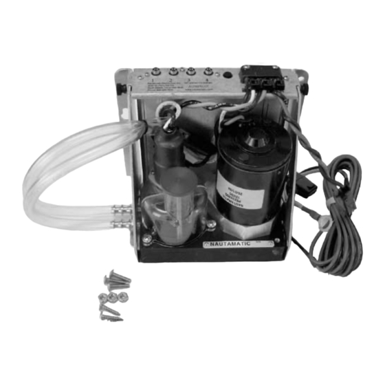
Page 4: Parts List
TR-1 Gold Autopilot System Parts List Electro-Hydraulic unit……………….……. 120-2100-00 Kinked tubing with tie wrap………………. 3 ea. Truss head machine screws #8-32x 3/4 3 ea. Lock washer nuts #8-32……………… 3 ea. Truss head sheet metal screws #8 x 3/4 Sensor Ball Unit……………………………….…….. 120-2200-00 Sensor Ball Bracket …………………………………. - Page 5 Handheld/Remote Unit...…………………………. 120-2020-00 Cylinder Mounting Kit………………… (Motor Specific) 18 feet Hydraulic Hose………………………………… 120-0013-01 Steering Cylinder………………………………………... 120-0900-00 Throttle Actuator ( Motor Specific)………………………. 1 pt. Hydraulic Fluid 120-0001-01(Bio-Soy)………………………………...
-
Page 6: Specifications
E-H unit Sensor Ball Remote Deckmount/Tach Battery Cable Fluid Supply Voltage Maximum Current Inline Fuse Operating Ambient Temperature This manual comprises two major sections. The first section is a guide to installation of the “onboard” components of the autopilot system on your boat. The second section is a guide to adjusting and operating your system. - Page 7 Access The Electrohydraulic Unit is the place where all the components connect together and the place where fluid is added and fluid level is checked. Leave room for service loops in the cables and hoses. The Deckmount switch should be easy to reach with your free hand when your other hand is on the kicker tiller.
-
Page 8: System Layout
Throttle Actuator Mounts on carburetor on motor. Tach sensor wire:Attaches to spark plug wire on kicker. Deckmount On/Off switch: Mounts near kicker motor, near transom. System Layout Handheld/Remote Cylinder Cylinder Mounting Bracket: Mounts on Motor lower end. Sensor Ball: Mount in front 1/2 of boat. -
Page 9: Tools
You should gather the following tools before beginning installation. See throttle and cylinder supplements for any additional tools that may be needed for your application. Tools Power Drill #1 Phillips screw driver .125 (1/8) or 3.17 mm dia. drill .469 (15/32) or 11.90 mm dia. drill Roll of masking tape Rags Knife... - Page 10 Fig. 6 Fig. 7 You may run the red and black wires to the battery box now, but do not connect to the battery yet. Mounting Hydraulic Unit Step Two (Locking unit in place) Floor Mount: Set the unit on the floor in front of screws.
-
Page 11: Installation Of Sensor Ball (Compass)
Installation of the Sensor Ball The Sensor (Compass) Ball needs to be mounted forward of the center of your boat. Make sure you mount it away from magnetic disturbances (stereo speakers, wiper motors, anchors). You will need to calibrate your compass on the water after installation of system and before you use the autopilot. - Page 12 Fig. 9-A Fig. 10-a Fig. 10-b Run the wire back to the E-H unit. The wire connector from the Sensor Ball is labeled number 4. It connects to the E-H unit at connector 4, as shown in fig.10-a or 10-b. (this will depend on your ECU wiring configuration).
-
Page 13: Installation Of Deckmount/ Tach
Installation of the Deckmount and Tach Fig. 11 Fig. 11-A Step One: (Deckmount) If the material you wish to mount the Deckmount switch in is less than ¼” thick: Drill a hole 15/32 Diameter perpendicular to the surface. Unscrew the bezel from the switch and leave one washer on the neck. -
Page 14: Installation Of Handheld/Remote
Installation of the Handheld/Remote Fig. 12 Installation of the Cylinder Kit and Throttle Actuator Refer to the manuals supplied with the throttle and steering cylinder kits, and install these parts before continuing with the procedures that follow. If you do not use the throttle actuator, it is recommended that you coat #2 pico connector with a grease to protect it from corrosion. -
Page 15: Connect & Fill Hydraulic System
Before you start……… As with all hydraulic systems, it is very important to keep any dirt or debris from entering the system. If you haven’t already, loosen the steering tension adjustment on your motor to the minimum setting. The motor should turn very easily. (If necessary refer to your outboard motor’s owner’s manual). - Page 16 Step Three Arrange the hose at the cylinder end so that none will kink and they are hanging free. Put a piece of tape on the right hose at the cylinder end to identify it. You will need to know this when it’s time to connect the hose to the cylinder.
- Page 17 Fig. 16 Slide the rod into the cylinder as far as it will go. Now remove the short clear hose from the cylinder and drain the fluid from the tubing into the bottle. Be sure both cylinder fittings are full to the top. Point the rod end of the cylinder toward the pin that engages it but leave it pushed into the cylinder.
-
Page 18: Gps Connections
Step Eight (Check hose fit) Check to see that the hose is free to move back and forth with motor. Tie wrap as necessary to hold hose in place. See Fig. 18 Step Nine (Hose Clamp) Place hose clamps over hose and fittings at cylinder end. Fig. 18-a Step Ten (Top off the system) Manually turn the motor back and forth several times. -
Page 19: System Functions And Features
Introduction to Operation and Adjustments This section of this document provides you with information that will let you take advantage of your TR-1 Gold autopilots' capabilities. We have made every effort to minimize the pain in getting you up to speed as a user of the TR-1, however, programmable devices such as your TR- 1, are often difficult to learn to use and to program. -
Page 20: Operating The System
6. Man Overboard. The autopilot will execute a turn to the reciprocal course and pass near the maneuver initiation point. 7. GPS steering. (Some GPS units may not support these features.) 7a. The autopilot will steer to a waypoint or series of waypoints. 7b. -
Page 21: Power On/Off (Deckmount)
Turn power on by pressing and releasing the Deckmount switch. Turn the power off by pressing and holding the switch down until the Deckmount switch light has extinguished (about four seconds). Power on is indicated by illumination of the Deckmount switch button and the STBY LED on the Hand Held. -
Page 22: Change Heading With Rcah (Changing Heading While In Autopilot)
Change Heading with RCAH Change Heading While in Autopilot (RCAH) You can steer to a new heading with the Straight Right Arrow and Straight Left Arrow buttons. Momentary presses of either of these buttons will cause the pilot to alter the heading by one degree per press. -
Page 23: Gps Steering
GPS Steering The GPS steering functions are not guaranteed to work with all GPS systems. Each manufacturer of GPS equipment puts his own spin on how to assemble the data on the NMEA data bus. Sometimes the data on the bus will not conform to the needs of the autopilot. -
Page 24: Steer To Waypoint
Steer To Waypoints (GPS Steering) If you press and release the GPS (Select Load) button when the autopilot is in heading hold and the GPS has an active route, the pilot will steer to the selected waypoint. If you are more than 1000 ft. off the courseline the pilot will steer directly at the waypoint and not try to remove crosstrack error. -
Page 25: Search Pattern
Search Pattern (GPS Steering) To do an outward spiraling search from a waypoint, setup the special function buttons for search patterns. (See page 28 Selecting Special Functions) When you are near the waypoint you want to search from, select “go to” this waypoint on your GPS. With the pilot in heading hold, press and release the GPS (Select Load) button and then press and release one of the Bent Arrow buttons. -
Page 26: Step Turns, Change Heading With
The autopilot will attempt to perform any of its steering functions when the boat is backing in reverse gear. To engage the system in reverse: 1) Start from Standby. 2) Press and hold the GPS (REV) button. 3) Press and release the Auto/Stby button. 4) Release the GPS (REV) button. If you program the Bent Right Arrow and Bent Left Arrow buttons for Circles, pressing the Bent Right Arrow button will cause your boat to be driven in a clockwise (from above) circle with a lap time between 1 and 90 minutes (programmable). -
Page 27: Idle/Resume
Throttle Up/Down Increase throttle by pressing the Up Arrow button. Decrease throttle by pressing the Down Arrow button. The electric throttle runs in parallel with the tiller throttle, this means that you can't reduce the RPM with the electric throttle if the tiller throttle is set high. It is best to always run with the tiller throttle set to idle. -
Page 28: Selecting Special Functions
When you select special functions, by the methods described below, you are simply choosing which function is to be executed by the pilot when you push one of the tree special function buttons. The Idle/Resume button is programmable to provide either Idle/Resume or MOB or Zigzags (other). The Bent Left Arrow button is programmable to provide either Steps or Circles or Remote Steer. -
Page 29: Setup, How To Make Changes With
How to Make System Changes with Setup 1. Autopilot must be in Heading Hold or Standby Mode before selection process can start. (AUTO LED solid on or STBY LED solid on. No other LED's on.) 2. Press and release the Setup Button. The Setup LED will illuminate to indicate the system is ready to take setup commands (button pushes). -
Page 30: Setup Codes, Table Of
Tachometer Codes Setup Action Code # Stby Safety Monitor Tach on/off Show RPM Throttle Codes Throttle Speed Throttle Delay Hydraulic Codes Reverse Hoses Automated Setup Codes Calibrate Compass Load Factory Compass Load Factory Pilot Special Function Setup Codes Degrees per Step Circle Time Zig-Zag Amplitude Zig-Zag Period... -
Page 31: Explanation Of Codes
Setup Action Setup Action Navigation Gain Navigation Function Codes Navigation Gain Navigation Trim Gain Navigation Trim Gain Use Synthetic XTE Setup Action Use Synthetic XTE Change Sign of XTE Navigation Gain Change Sign of XTE Use Magnetic North Navigation Trim Gain Use Magnetic North Set North Use Synthetic XTE... - Page 32 Code 35. Since the boat dynamics change with RPM the autopilot retunes itself as it sees the RPM change. Most boats will work well with the mild setting. The easiest way to set the speed schedule is to first get tuned up and working well at low speed, then run at high speed. 1) If steering response is sluggish, increase code 35.
-
Page 33: Adjusting Your Autopilot (Tuning And Setup) Pages
Compass Calibration and Tuning your Autopilot Your autopilot needs to be “tuned” to your boat and motor configuration. This is the most difficult part of getting your pilot running the best it can. Have patience and don’t even try to do this until you have some time on a nice calm day. - Page 34 3. Tune the feedback gains. Start from [Standby] mode. (The STBY light should be lit on the handheld.) • Press the [Setup] button and press and light up code 2 (Number 2 LED on the handheld) - this is the rudder gain adjustment code. Run your boat in a straight line at 1/3 to 1/2 full speed and engage the pilot by pressing the Auto/Stby button.
-
Page 35: Rudder And Counter Rudder Gain Pages
4. Set North: You must do this, if the autopilot is connected to the GPS. To run a GPS course requires that the autopilot compass is in agreement with the GPS’s course estimate. You need to set North with the pilot in standby mode. Do not set North except in calm sea’s and un-accelerated conditions. You should be running at a reasonably high speed, it won’t hurt to be running on plane with your main engine. - Page 36 Well Tuned Response The objective of tuning is to set the gains so as to elicit a response with a shape like this that reaches the 5 degree heading in as short of a time interval as possible. You know that you have reached this tune when attempts to increase the Rudder Gain or Decrease the counter rudder gain results in oscillations in heading.
- Page 37 Rudder Gain Effects The Rudder Gain Effects plot shows that too low a Rudder Gain will make the heading response slow and sloppy, if the Rudder Gain is turned down much lower the heading response will become unstable (do everything but hold heading). The plot also shows, when the Rudder Gain is set too high, that the heading oscillates with a high frequency, the rudder will be seen to be oscillating with large amplitude and high frequency as the Rudder Gain becomes "too much."...
-
Page 38: Limited Warranty
(if applicable), your return shipping address, and a daytime telephone number. Phone: 1-866-559-0229 e-mail: autopilot.support@garmin.com After you receive the RMA number, securely package the unit and ship it (insured) to the following address: Garmin International, Inc. 1200 E. 151 Street RMA number (insert your RMA number here)
Need help?
Do you have a question about the TR-1 GOLD 906-2000-00 and is the answer not in the manual?
Questions and answers