Garmin GHP 10 Marine Autopilot System Installation Instructions Manual
Hide thumbs
Also See for GHP 10 Marine Autopilot System:
- Declaration of conformity (1 page) ,
- Reference (1 page) ,
- Installation instructions manual (48 pages)
Table of Contents
Advertisement
Quick Links
GHP
10 Installation Instructions
™
To obtain the best possible performance and to avoid damage to your
boat, install the Garmin
GHP 10 marine autopilot system according
®
to the following instructions. Professional installation of the autopilot
system is highly recommended.
Read all installation instructions before proceeding with the
installation. If you experience difficulty during the installation, contact
Garmin Product Support.
NOTE: There is an installation checklist on the last page of these
instructions. Remove the last page and refer to the checklist as you
proceed through the GHP 10 installation.
Registering Your Device
Help us better support you by completing our online registration today.
• Go to http://my.garmin.com.
• Keep the original sales receipt, or a photocopy, in a safe place.
For future reference, write the serial number assigned to each
component of your GHP 10 system in the spaces provided on
The serial numbers are located on a sticker on each component.
Contacting Garmin
Contact Garmin Product Support if you have any questions while using
your GHP 10.
In the USA, go to www.garmin.com/support, or contact Garmin USA
by phone at (913) 397.8200 or (800) 800.1020.
In the UK, contact Garmin (Europe) Ltd. by phone at 0808 2380000.
In Europe, go to
www.garmin.com/support
for in-country support information, or contact Garmin (Europe) Ltd. by
phone at +44 (0) 870.8501241.
GHP 10 Installation Instructions
page
3.
and click Contact Support
Important Safety Information
WaRnInGS
You are responsible for the safe and prudent operation of your
vessel. The GHP 10 is a tool that will enhance your capability to operate
your boat. It does not relieve you from the responsibility of safely
operating your boat. Avoid navigational hazards and never leave the
helm unattended.
Always be prepared to promptly regain manual control of your boat.
Learn to operate the GHP 10 on calm and hazard-free open water.
Use caution when operating the GHP 10 near hazards in the water, such
as docks, pilings, and other boats.
See the Important Safety and Product Information guide in the product
box for product warnings and other important information.
CautIon
Equipment to be connected to this product should have a fire enclosure
or be provided with a fire enclosure.
Always wear safety goggles, ear protection, and a dust mask when
drilling, cutting, or sanding.
When drilling or cutting, always check the opposite side of the surface.
Be aware of fuel tanks, electrical cables, and hydraulic hoses.
Notice
1
Advertisement
Table of Contents

Related Manuals for Garmin GHP 10 Marine Autopilot System


Summary of Contents for Garmin GHP 10 Marine Autopilot System
-
Page 1: Ghp ™ 10 Installation Instructions
GHP 10. In the USA, go to www.garmin.com/support, or contact Garmin USA by phone at (913) 397.8200 or (800) 800.1020. In the UK, contact Garmin (Europe) Ltd. by phone at 0808 2380000. In Europe, go to www.garmin.com/support for in-country support information, or contact Garmin (Europe) Ltd. by phone at +44 (0) 870.8501241. -
Page 2: Table Of Contents
10 Installation Instructions ...1 ™ Registering Your Device ... Contacting Garmin... Important Safety Information ... GHP 10 Package Contents and tools needed . Main Components ..3 ...3 Hydraulic Pump and Motor ...3 Shadow Drive ...3 GHC 10 ...3 Cables and Connectors ... CCU/ECU Interconnect Cable ...4 Alarm...4 ECU Power Cable ...4... -
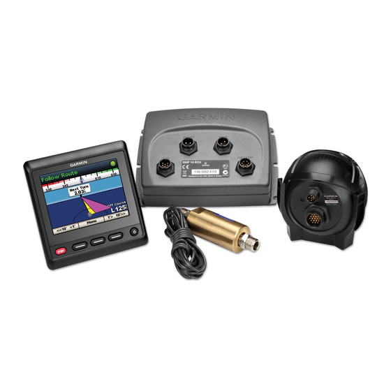
Page 3: Ghp 10 Package Contents And Tools Needed
All the components, except the hydraulic pump, are included in the GHP 10 core box. If any parts are missing, contact your Garmin dealer immediately. Record the serial number of each component in the space provided. -
Page 4: Cables And Connectors
CCU to the alarm and to the yellow wire from the GHC 10. CCu/ECu Interconnect Extension Cables When installing the GHP 10 system, you may need to mount the CCU farther than 16 ft. (5 m) from the ECU. Garmin offers optional replacement or extension cables for purchase if this is necessary. type... -
Page 5: Installation Preparation
• Ensure the appropriate pump has been correctly installed on your boat. NOTE: If you have questions about the appropriate pump for your boat, contact your local Garmin dealer or Garmin Product Support for more information. • If possible, use larger inside diameter hydraulic hoses on your steering system. -
Page 6: Nmea 2000 Connection Considerations
GHC 10 data cable Speed Source Connection Considerations For optimal performance in all conditions, Garmin recommends connecting to a NMEA 2000 or analog tachometer speed source. Each speed source in the table is listed in order of best to least in terms of autopilot performance. -
Page 7: General Connections Diagram
General Connections Diagram Refer to this diagram for component-interconnection reference only. Follow the detailed installation instructions for each component. ➌ Item Description Important Considerations GHC 10 ➊ GHC 10 data cable In order for the autopilot to turn on, the yellow wire from this cable must be connected to the yellow wire from ➋... -
Page 8: Single-Helm Layout Guidelines
Single-helm Layout Guidelines ➎ NOTE: This diagram is for planning purposes only. Specific connection diagrams are included in the detailed installation instructions for each component. Hydraulic connections are not shown in this diagram. Item Description Important Considerations GHC 10 In order for the autopilot to turn on, the yellow wire from the GHC 10 data cable must be connected to the yellow wire ➊... -
Page 9: Dual-Helm Layout Guidelines
Dual-helm Layout Guidelines ➎ NOTE: This diagram is for planning purposes only. Specific connection diagrams are included in the detailed installation instructions for each component. Hydraulic connections are not shown in this diagram. Item Description Important Considerations GHC 10 In order for the autopilot to turn on, the yellow wire from the GHC 10 data cable must be connected to the yellow wire ➊... -
Page 10: Installation Procedures
Installation Procedures After you have completely planned the GHP 10 installation on your boat, and have satisfied all the hydraulic, mounting, and connection considerations for your particular installation, you can begin mounting and connecting the components. Shadow Drive Installation To install the Shadow Drive, connect it to the hydraulic steering line of your boat and connect it to the CCU/ECU interconnect cable. -
Page 11: Securing The Ccu In The Ccu Bracket
Stainless-steel screws may bind when screwed into fiberglass and overtightened. Garmin recommends applying an anti-galling, stainless Ground anti-seize lubricant to the screws before installing them. Before you can mount the GHC 10, you must select a mounting location... -
Page 12: Connecting The Ghc 10
To use advanced features of the GHP 10, optional NMEA 2000-compatible devices, such as a GPS device, can be connected to the NMEA 2000 network. For more information on NMEA 2000, go to www.garmin.com. Connecting the GHC 10 to an Existing nMEa 2000 network 1. Determine where to connect the GHC 10 ➊ to your existing NMEA 2000 backbone ➋... -
Page 13: Connecting The Ccu To An Existing Nmea 2000 Network
7. Connect the drop cable to the T-connector you added in step 3, and to the GHC 10. NOTE: In order for the autopilot to turn on, the yellow wire from the GHC 10 data cable be connected to the yellow wire from the CCU/ECU interconnect cable, and the black wire from the GHC 10 data cable must be connected to the same ground as the ECU (page... -
Page 14: Connecting Optional Devices To The Ghp 10 Autopilot
Connecting optional Devices to the GHP 10 autopilot System To use advanced features of the GHP 10, optional NMEA 2000-compatible or NMEA 0183-compatible devices, such as a GPS device, can be connected to the NMEA 2000 network or to the GHC 10 through NMEA 0183. nMEa 0183 Connection Considerations • To identify the Transfer (Tx) A(+) and B(-) wires for your NMEA 0183-compatible device, consult the installation instructions for your device. -
Page 15: Selecting The Speed Source
• If you did not connect a speed source, select None. ◦ If the autopilot does not perform well using None as the speed source, Garmin recommends connecting a tachometer or GPS as the speed source. Verifying the tachometer This procedure does not appear if GPS or None is selected as the speed source. -
Page 16: Calibrating The Compass
Calibrating the Compass 1. Drive your boat at cruising speed in a straight line. 2. Select Begin, and continue to drive in a straight line. 3. When instructed, turn the boat slowly clockwise, taking care to make the turn as steady and flat as possible. Turn slowly so that the boat DOES NOT list. -
Page 17: Adjusting The Autopilot Gain Settings
adjusting the autopilot Gain Settings NOTE: When you manually adjust the rudder gain (or counter gain), make relatively small adjustments, and adjust only one value at a time. Test the change before making additional adjustments. 1. Enable the advanced configuration procedure 2. On the GHC 10, select Menu > Setup > Dealer Autopilot Configuration >... -
Page 18: Appendix
appendix nMEa 0183 Connection Diagrams The following three connection diagrams are examples of different situations you may encounter when connecting your NMEA 0183 device to the GHC 10. Example one of three: two-way nMEa 0183 Communication ➋ ➌ ➊ ➌ > ➍ > > ➎ > ➏ GHC 10 ➊ NMEA 2000 network (provides power to the GHC 10) ➋... -
Page 19: Nmea 2000 Pgn Information
Device Specification Measurement Dimensions in. diameter (91.4 mm) Weight 5.6 oz. (159 g) Temperature From 5°F to 140°F (from -15°C to 55°C) range Case material Fully gasketed, high-impact aluminum alloy, waterproof to IEC 529 IPX7 standards CCU/ECU 16 ft. (5 m) interconnect cable length NMEA 2000... -
Page 20: Nmea 0183 Information
nMEa 0183 Information When connected to optional NMEA 0183-compatible devices, the GHC 10 uses the following NMEA 0183 sentences. type Sentence Receive grme Transmit GHP 10 Configuration Settings Although all of the configuration is typically completed automatically through wizards, you can manually adjust any setting NOTE: Depending upon the configuration of the autopilot, certain settings may not appear. - Page 21 Category Setting Rudder Gains High Speed Gain Rudder Gains High Speed Counter NMEA Setup NMEA Checksum NMEA Setup Reversed XTE If the connected NMEA 0183 Navigation Setup Navigation Gain Navigation Setup Navigation Trim Gain GHP 10 Installation Instructions Description Category Allows you to set the rudder Steering System gain for high speeds.
-
Page 22: Error And Warning Messages
Error and Warning Messages Error Message Cause ECU voltage is low The ECU supply voltage goes below 10 Vdc for longer than 6 seconds. Autopilot is not The autopilot is no receiving navigation longer receiving valid data. Autopilot placed navigation data. in heading hold. This message will also be shown if navigation is stopped... -
Page 23: Ccu Mounting Template
ECU Mounting Template CCu Mounting template Up, when installing on a ➊ vertical surface GHP 10 Installation Instructions ➊... -
Page 25: Ghp 10 Installation Checklist
GHP 10 Installation Checklist Detach this checklist from the installation instructions and use it during the GHP 10 installation process. Read all installation instructions before installing the GHP 10. Contact Garmin Product Support if you have any questions during the installation process. Refer to the diagram on... - Page 26 All rights reserved. Except as expressly provided herein, no part of this manual may be reproduced, copied, transmitted, disseminated, downloaded or stored in any storage medium, for any purpose without the express prior written consent of Garmin. Garmin hereby grants permission to download a single copy of this manual onto a hard drive or other electronic storage medium to be viewed and to print one copy of this manual or of any revision hereto, provided that such electronic or printed copy of this manual must contain the complete text of this copyright notice and provided further that any unauthorized commercial distribution of this manual or any revision hereto is strictly prohibited.
Need help?
Do you have a question about the GHP 10 Marine Autopilot System and is the answer not in the manual?
Questions and answers