Table of Contents
Advertisement
Quick Links
This .pdf document is bookmarked
Operating Instructions and Parts Manual
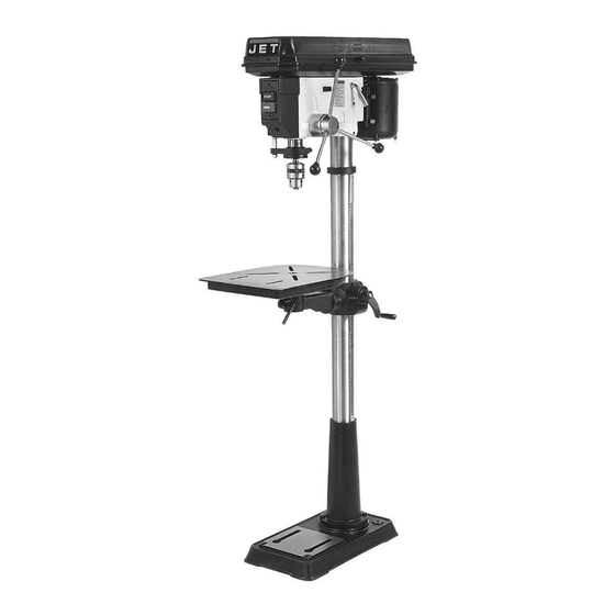
Drill Press
Models JDP-15M/MF
WALTER MEIER (Manufacturing) Inc.
427 New Sanford Road
LaVergne, Tennessee 37086
Part No. M-354165
Ph.: 800-274-6848
Revision A1 04/2010
www.waltermeier.com
Copyright © 2010 Walter Meier (Manufacturing) Inc.
Advertisement
Table of Contents

Related Manuals for Jet DP-15M


Summary of Contents for Jet DP-15M
- Page 1 This .pdf document is bookmarked Operating Instructions and Parts Manual Drill Press Models JDP-15M/MF WALTER MEIER (Manufacturing) Inc. 427 New Sanford Road LaVergne, Tennessee 37086 Part No. M-354165 Ph.: 800-274-6848 Revision A1 04/2010 www.waltermeier.com Copyright © 2010 Walter Meier (Manufacturing) Inc.
-
Page 2: Warranty And Service
Walter Meier is consistently adding new products to the line. For complete, up-to-date product information, check with your local Walter Meier distributor, or visit waltermeier.com. WARRANTY JET products carry a limited warranty which varies in duration based upon the product (MW = Metalworking, WW = Woodworking). WHAT IS COVERED? This warranty covers any defects in workmanship or materials subject to the exceptions stated below. -
Page 3: Table Of Contents
Table of Contents Table of Contents ..........................3 Warnings............................4 Specifications .............................6 Shipping Contents ..........................7 Required Tools ...........................7 Assembly ............................8 Before Assembly ..........................8 Column Assembly ...........................8 Table Bracket ..........................8 Crank Handle and Table Lock Handle....................8 Column Lock Handle ........................9 Table Installation ..........................9 Head Assembly ..........................9 Chuck and Arbor Installation ......................9 Chuck and Arbor Removal ...................... -
Page 4: Warnings
Warnings 1. Read and understand the entire owners manual before attempting assembly or operation. 2. Read and understand the warnings posted on the machine and in this manual. Failure to comply with all of these warnings may cause serious injury. 3. - Page 5 20. Keep visitors a safe distance from the work area. Keep children away. 21. Make your workshop child proof with padlocks, master switches or by removing starter keys. 22. Give your work undivided attention. Looking around, carrying on a conversation and “horse-play” are careless acts that can result in serious injury.
-
Page 6: Specifications
Specifications Model Number ............JDP-15M........... JDP-15MF Stock Number .............. 354165..........354166 Swing.................. 15”............15" Type ................Bench............ Floor Drilling Capacity..............5/8”............5/8” Chuck Size ................. 5/8”............5/8” Spindle Travel ..............3-1/8”........... 3-1/8” Spindle Distance to Base ..........16-1/2”............48" Spindle Distance to Table (max.) .......... 24”............29" Table Size (Length x Width) ........16-1/2"... -
Page 7: Shipping Contents
Shipping Contents Unpack the carton and verify that all parts listed below are included. Other Material Main Parts 1 ea Owner’s Manual 1 ea Head Assembly 1 ea Warranty Registration Card 1 ea Table 1 set Column and Table Bracket Assembly 1 ea Base Required Tools... -
Page 8: Assembly
1. Remove the contents from the shipping container. 2. Compare the contents of the shipping container with the list found above. Report any shortages or damage to your JET distributor. 3. Clean all rust protected surfaces with kerosene or a light solvent. -
Page 9: Column Lock Handle
Head Assembly Referring to Figure 7: 1. With the aid of a second person, carefully lift the head onto the column top and slide it down into position Figure 4 The head assembly is heavy! Use care when lifting onto the column! Column Lock Handle 2. -
Page 10: Chuck And Arbor Removal
1. Use a pencil to mark the depth the bit will drill into the workpiece. 2. With the drill bit in the chuck, lower downfeed handle to advance bit to your mark (A). 3. With your other hand, advance the lock nuts (B) on the depth stop rod until they are snug to the seat (C). -
Page 11: Return Spring Adjustment
6. Tighten two bar knobs (E, Fig. 11). Belts are properly tensioned when finger and thumb pressure midway between the two pulleys causes approximately ½” deflection. Figure 11 Figure 12 Return Spring Adjustment The return spring is adjusted at the factory and should need further... -
Page 12: Work Light
Work Light Install a light bulb, no larger than 60 watts into the socket accessed from beneath the head. The rocker switch controls the light switch (D, Fig. 13). IMPORTANT: If the drill press is connected to 230 volt power, you must install a bulb rated for 230 volt. -
Page 13: Maintenance
UL/CSA listed plug suitable for 230V operation (D). Contact your local Authorized All of the ball bearings are packed with grease at JET Service Center or qualified electrician the factory. They require no further lubrication. for proper procedures to install the plug. -
Page 14: Grounding Instructions
Grounding Instructions Extension Cords Make sure your extension cord is in good condition. When using an extension cord, be This tool must be grounded while in use to sure to use one heavy enough to carry the protect the operator from electric shock. current your machine will draw. -
Page 15: Troubleshooting
Troubleshooting Trouble Probable Cause Remedy Drill press unplugged from wall, or Check all plug connections. motor. Drill press will not Fuse blown, or circuit breaker tripped. Replace fuse, or reset circuit breaker. start. Cord damaged. Replace cord. Starting capacitor bad. Replace starting capacitor. -
Page 16: Replacement Parts
Troubleshooting (cont.) Trouble Probable Cause Remedy Bent drill bit. Replace drill bit. Excessive drill bit Worn spindle bearings. Replace spindle bearings. runout, or wobble. Bit, or chuck not properly installed. Reinstall the bit, or chuck properly. Adjust spring tension. See the Return Quill returns too slow, Spring has improper tension. -
Page 17: Exploded View Drawing Jdp-15M/Mf
Exploded View Drawing JDP-15M/MF... -
Page 18: Parts List Jdp-15M/Mf
Parts List JDP-15M/MF Index No. Part No. Description Size 1A.... 10600110 ....Base for JDP-15M ................1 1B.... 10800101 ....Base for JDP-15MF ................1 2A.... JDP15-1002A ..Column Holder for JDP-15M ..............1 2B.... 10600204 ....Column Holder for JDP-15MF .............. 1 3 ....TS-2279121 ....Hex Socket Set Screw ........M10-12 ...... 3 4A.... -
Page 19: Parts List Jdp-15M/Mf
Parts List JDP-15M/MF Index No. Part No. Description Size 59 .... 2001ZZ6204 ....Ball Bearing..................1 61 .... 2001ZZ6203 ....Ball Bearing..................1 62 .... TS-2360161 ....Washer ............M16 ......1 63 .... 10606301 ....Nut Lock .................... 1 64 .... 10606401 ....Spindle Nut ..................1 65 .... -
Page 20: Parts List Jdp-15M/Mf
Parts List JDP-15M/MF Index No. Part No. Description Size 166 ..JDP15-1166 ....Speed Diagram .................. 1 169 ..JDP15-1169 ....Trade-Mark Label ................1 170 ..2658MZDU36 ..Drive Screw............Φ 2.3-5 ...... 6 601 ..TS-2245082 ....Cr. Re. Pan Head Screw ........M5-8 ......4 602 .. -
Page 21: Wiring Diagram
Wiring Diagram JDP – 15M/MF – 115V JDP – 15M/MF – 230V... - Page 22 NOTES...
- Page 23 NOTES...
- Page 24 WALTER MEIER (Manufacturing) Inc. 427 New Sanford Road LaVergne, Tennessee 37086 Phone: 800-274-6848 www.waltermeier.com...
Need help?
Do you have a question about the DP-15M and is the answer not in the manual?
Questions and answers