Furuno FM-8500 Installation Manual
Vhf radiotelephone
Hide thumbs
Also See for FM-8500:
- Operator's manual (99 pages) ,
- Operator's manual (2 pages) ,
- Manual (493 pages)
Table of Contents
Advertisement
Quick Links
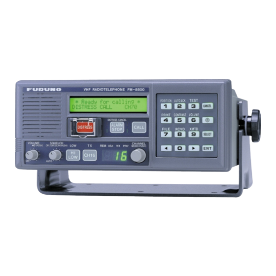
VHF RADIOTELEPHONE FM-8500
This manual provides the information necessary
for the installation of the FURUNO FM-8500
VHF Radiotelephone. For best performance
please follow the recommended procedures.
R
INSTALLATION MANUAL
Table of Contents
1. System Configuration ........... 1
2. Equipment Lists .................... 2
3. Mounting .............................. 8
4. Connections......................... 14
5. Initial Settings ...................... 21
Outline Drawings ....................D-1
Interconnection Diagram ....... S-1
Schematic Diagrams .............. S-2
Page
Advertisement
Table of Contents

Related Manuals for Furuno FM-8500


Summary of Contents for Furuno FM-8500
-
Page 1: Installation Manual
VHF RADIOTELEPHONE FM-8500 This manual provides the information necessary for the installation of the FURUNO FM-8500 VHF Radiotelephone. For best performance please follow the recommended procedures. INSTALLATION MANUAL Table of Contents 1. System Configuration ... 1 2. Equipment Lists ... 2 3. - Page 2 9 - 5 2 , A s h i h a r a - c h o , N i s h i n o m i y a , J a p a n T e l e p h o n e : 0 7 9 8 - 6 5 - 2 1 1 1 T e l e f a x : 0 7 9 8 - 6 5 - 4 2 0 0...
- Page 3 "NOTICE", "CAUTION" and "WARNING" notices appear throughout this manual. It is the responsibility of the installer of the equipment to read, understand and follow these no- tices. If you have any questions regarding these safety instructions, please contact a FURUNO agent or dealer. WARNING CAUTION...
- Page 4 WARNING Hazardous voltage. Can shock, burn or cause serious injury. Do not work inside the equip- ment unless totally familiar with electrical circuits. Turn off the power at the mains switch- board before beginning the installation. Post a warning sign near the switchboard to indicate that power should not be applied while the equipment is being installed.
-
Page 5: System Configuration
Ship’s Mains 100/220 VAC AC/DC 50/60 Hz, 1 Power Supply Unit Radio Battery PR-300 24 VDC 1. System Configuration Antenna DSC Antenna TRANSCEIVER UNIT FM-8500 Navigation Device Distress Message Controller DMC-5 Remote Station DB-700 or Distributor DB-500 Printer Printer Interface... - Page 6 Standard Supply l l a i t a 2. Equipment Lists *: Version number...
-
Page 7: Optional Equipment
Optional Equipment i x i l a i l a i i t a r t s t s i r e t e r t r e l r e t r e t ) t e ) t e... -
Page 12: Transceiver Unit
Standard compass: 1.6 m Steering compass: 1.2 m Note: Take great care not to press the DISTRESS switch during the installation. If you accidentally press the switch, immediately turn off the equipment and contact appropriate authority by telephone. 3. Mounting... - Page 13 Overview of mounting methods Tabletop Overhead Bulkhead Flush Mount Figure 1 Overview of mounting methods...
- Page 14 Mounting procedure for tabletop, overhead and bulkhead mounting 1. Using the hanger as a template, mark fixing holes in the mount- ing location. 2. Fix the hanger to the mounting location with wood screws and washers (supplied). (For added support, use nuts, bolts and wash- ers instead of wood screws.) 3.
-
Page 15: Mounting Considerations
• The higher the antenna is mounted above the horizon, the further the communications range. Mounting procedure The basic mounting procedure for antennas supplied by FURUNO is as follows, however consult appropriate outline drawing for details. 1. Fasten the antenna bracket to the stanchion. - Page 16 For Convention vessels, both AC and DC power must be fed to the FM-8500, via an AC/DC power supply. When AC input fails, DC power is supplied. FURUNO can supply an AC/DC power supply unit, the PR-300.
- Page 17 Printer Interface (option) Printer (option) Mounting Fixture External Loudspeaker (option) Printer Interface IF-8500 is connected between the printer PP-510 and the transceiver unit. See outline drawing on page D-11. Refer to the printer outline drawing on page D-12 for mounting dimensions.
- Page 18 Message Controller Interface IF-8500. DMC-5. Figure 5 FM-8500, rear view Convention vessels, 100/220 VAC ship’s mains Convention vessels must supply both AC and DC power to the FM- 8500, via an AC/DC power supply unit. Both AC and DC are sup- plied by the AC/DC power supply unit, and when AC input fails DC power is activated.
- Page 19 Connection of VHF Antenna Radio battery (24 VDC) Attach the connector supplied to the power cable and plug it into the 24VDC connector at the rear of the transceiver unit. Connect the wire ends to the radio battery line. The VHF antenna is connected to the transceiver unit with a 50 ohm coaxial cable, type 5D-2V.
- Page 20 Connection of DSC Antenna Connection of Handset Grounding the Transceiver Unit Connection of AC/DC Power Supply Unit PR-300 (option) 100V 100VAC SHIP'S MAINS 110VAC SHIP'S MAINS The DSC antenna is connected to the transceiver unit with a 50 ohm coaxial cable, type 5D-2V. Attach an M-type plug to the cable (if necessary) as shown in Figure 6.
- Page 21 Figure 8 AC-DC power supply unit PR-300, rear view Ground Connect a ground wire between ship’s superstructure and a fixing screw on the PR-300. Lamp (green) FURUNO DC IN DC OUT CAUTION Ground the equipment to prevent electrical shock and mutual interference.
- Page 22 The following equipment can be connected to the FM-8500: • Distress Message Controller DMC-5 • Remote Station RB-700 (or Distributor DB-500) • Navigator : the FM-8500 can receive the following data sentences in NMEA format (Ver. 1.5). GLL: Latitude and longitude RMC: Generic navigation information RMA: Loran C data (L/L, LOPs, etc.)
- Page 23 Cables required i t a r t s t s i Wing handset Two types of wing handsets are available: HS-6000FZ6 (carbon MIC) and HS-6000FZ5 (dynamic MIC). Change jumper connections on the CONTROLLER Board as shown in Figure 9 according to hand- set connected.
- Page 24 Procedure 1. Release write protection, referring to service manual for the procedure. TEST display appears. TEST VHF ch70 manual Figure 10a Test display 2. Press SELECT key, 9 key, RT key, and then press ENT key four times. RT4-TxAF MONITOR OFF[1] ON[2] Figure 10b TxAF monitor screen 3.
- Page 25 Printer Interface Refer to page S-1. Figure 10e...
-
Page 26: Initial Settings
Overview Entering Ship's ID This chapter provides the information necessary for setting up the following: 1) Ship's ID number 2) DSC block 3) VHF block 4) Channel system 5) Protection (Lock initial settings) Procedure 1. Rotate the VOLUME knob clockwise to turn on the equipment. “TEST”... - Page 27 Sub (VHF). The default setting is “CH70” as main unit. For sub unit, do the following. Procedure 1. Rotate the VOLUME knob on the sub FM-8500 clockwise to turn it on. 2. Press the SELECT and 9 keys to display the System menu.
- Page 28 3. Disable or enable the USA/WX mode. 4. Press the ENT key. The following menu appears. RT 1-Mode:private< OFF > OFF[1] ON[2] Figure 17 5. Disable or enable the PRIVATE channel mode. 6. Press the ENT key. RT 2-Hook work:CH16< ON > ON[1] OFF[2] Figure 18...
- Page 29 RT 5-Auto 1W< ON > ON[1] OFF[2] Figure 22 15. Disable or enable automatic power reduction (to 1 W) after a long transmission. 16. Press the ENT key. RT 6-Dual watch< ON > ON[1] OFF[2] Figure 23 17. Disable or enable dual watch. 18.
- Page 30 Setting Channel System 25. Enter squelch hold time in two digits, by following the formula below. Setting value x 20 (msec) = Time desired 26. Press the ENT key. The display changes to the System menu. Procedure 1. Press the right arrow key to select CH. 2.
- Page 31 For private channels mode 10. Press the CHANNEL knob to select private channel mode. P01/CH123<TX SIMP LOW> PRIV No.SELECT:[<][>]key Figure 29 11. Press the arrow keys to select private channel (P01 to P20) to set. P02/CH---<-- ---- ----> PRIV No.SELECT:[<][>]key Figure 30 12.
- Page 32 Locking Initial Settings Do the following to lock initial settings and enable normal operation. 1. Press the right arrow key to select P. 2. Press the ENT key. The following appears. Protection< OFF > Figure 35 3. Press the left arrow key to select ON. 4.
Need help?
Do you have a question about the FM-8500 and is the answer not in the manual?
Questions and answers