Table of Contents
Advertisement
Advertisement
Table of Contents

Related Manuals for Furuno FM-2721


Summary of Contents for Furuno FM-2721
- Page 1 Back MARINE VHF RADIOTELEPHONE FM-2721...
- Page 2 *00080897300* *00080897300* *00080897300* *00080897300* ( ( HIMA HIMA ) ) FM-2721 FM-2721 * 0 0 0 8 0 8 9 7 3 0 0 * * 0 0 0 8 0 8 9 7 3 0 0 * *OME56163E00* *OME56163E00*...
-
Page 3: Distress Call Procedure
DISTRESS Call Procedure Do the following when a life endangering situation 5. When you receive the distress acknowledgement arises on your vessel: call, you are automatically connected to CH16. Hook off the handset if it is not already off hook. Press the 1. -
Page 4: Receiving Distress Alert From Other Ship
Receiving Distress Alert from Other Ship General When the FM-2721 receives a distress alert from other vessel the LED (Red) lights and I N T L S I M P 2 5 W the FM-2721 sounds the distress alarm. L a t : 4 5 . 2 3 N 1. - Page 5 Should I transmit DIST ACK by voice or not? Distress alert received. Press the [Cancel] key to silence alarm. Read DISTRESS message. Acknowledge received from coast station? (Wait 3 mins.) If you can assist the vessel your vessel in distress, transmit near vessel in acknowledge by voice to Press the [Cancel] key...
-
Page 6: Safety Instructions
SAFETY INSTRUCTIONS For the operator CAUTION CAUTION Do not open the equipment. Handle the handset carefully. Only qualified personal should work Rough handling may affect its inside the equipment. watertight integrity. Do not disassemble or modify the equipment. Fire, electrical shock or serious injury can result. - Page 7 For the installer WARNING WARNING ELECTRICAL SHOCK HAZARD Be sure that the power supply is Do not open the equipment compatible with the voltage rating of the equipment. unless totally familiar with electrical circuits and Connection of an incorrect power supply service manual.
-
Page 8: Table Of Contents
Table of Contents DISTRESS Call Procedure........ i 3.5 Selecting Channel ..........15 3.6 Adjusting Squelch ..........15 Receiving Distress Alert from Other Ship..ii 3.7 Adjusting Loudspeaker Volume ......16 3.8 Muting the Loudspeaker ........16 SAFETY INSTRUCTIONS........ iv 3.9 Setting Transmitter Power ......... 16 System Configuration ........ - Page 9 4.9 Manual Entry of Position and Time....28 PRIVATE CHANNELS (NORDIC)......47 4.10 Storing IDs ............29 PRIVATE CHANNELS (NETHERLANDS-INLAND). 47 4.11 Storing Telephone Numbers ......30 General Notes on Operating Marine VHF..48 4.12 Storing Messages ........... 31 Rules and Manners ..........48 4.13 Message Log...........
-
Page 10: System Configuration
System Configuration VHF & CH70 RX ANT CH70 RX ANT (OPTION) (OPTION) 12V DC GROUND SPEAKER TRANSCEIVER 12VDC UNIT CH70 RX ANT SPKR FM-2721 (OPTION) IEC61162-1(NMEA) REMOTE 1 REMOTE 2 (SEM-21Q) MAX 50m GGA,RMC,GLL,ZDA (OPTION) (IEC61162-1) (HS-2721) (RB-2721A) (HS-2721) (RB-2721B) -
Page 11: Equipment Lists
Equipment Lists Standard Supply Name Type Code No. Remarks Handset HS-2721 Transceiver Unit FM-2721 Bracket RB-2721A For handset Installation CP05-08000 000-057-744 1 set Materials Spare Parts SP05-01600 004-542-060 1 set 10A Fuse: 2 pcs... - Page 12 Optional Supply (cont.) Name Type Code No. Remarks Bracket RB-2721B 000-057-738 1 set RB-2721A 000-057-737 1 set Handset HS-2721 000-057-736 1 set Antenna Kit AP05-00810 000-057-722 1 set RA106 Antenna Kit AP05-00820 000-057-723 1 set 150M-W2VN Antenna Kit AP05-00900 000-057-739 1 set 396-1 Loudspeaker...
-
Page 13: Introduction
Introduction A Word to the Owner of the FM-2721 Congratulations on your choice of the FURUNO FM-2721 Marine VHF Radiotelephone. We are confident that you will enjoy many years of trouble-free operation with this fine piece of equipment. For more than 50 years FURUNO Electric Company has enjoyed an enviable reputation for quality and reliability throughout the world. - Page 14 Features Conforms to the following regulations 25 W radiotelephone with control in palm European Standard EN 301 025 (VHF with Class D Intercom facility DSC) Compact transceiver unit allows installation where European Standard EN 300 698 (VHF used on space is limited inland waterways) ATIS (Automatic Transmitter Identification System) ITU Radio Regulations Appendix 18: Table of...
-
Page 15: Installation
1. Installation 1.1 Mounting Standard Steering Transceiver unit Transceiver unit 0.95 m 0.65 m The transceiver unit can be mounted on the overhead, Handset and Bracket 2.05 m 1.40 m a desktop or on a bulkhead. Select the mounting Loudspeaker (option) 2.20 m 1.50 m location considering the following:... - Page 16 bulkhead, and screw slots of the unit. Then fasten For bulkhead mounting, tighten upper tapping upper screws and washers. screws (supplied) and washers so there is 5 mm clearance between bottom of screw head and 4- 5 Fixing Hole Transceiver unit, top and side view...
- Page 17 Handset (Hanger) The length of the hanger cable is 5 m (optional HS-2721/RB-2721B: 50 m), so locate the handset hanger within 5 m of the transceiver unit. (77) 4.5 Fixing hole Remove six screws to remove the hanger cover, and fasten the hanger with two tapping screws (supplied) on the desktop or bulkhead.
- Page 18 Antenna Connection (option) Provide a location as high and clear as possible, free from the influence of nearby antenna, rigging and masts. However, any good quality antenna, complying with the following requirements, may be arranged locally. A high-gain antenna is preferable. If you are not sure, consult with your dealer. Frequency range: 155 MHz to 164 MHz Impedance: 50 ohms...
-
Page 19: Transceiver Connections
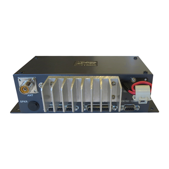
1.2 Transceiver Connections HS-2721 RB-2721A CH70 RX ANT Connect the optional antenna. Connect the optional CH70 RX antenna. Ground Transceiver Unit FM-2721 SPKR Connect the optional 12 VDC CH70 RX ANT IEC61162-1 (NMEA) SPKR REMOTE 1 REMOTE 2 IEC61162-1(NMEA) loudspeaker. - Page 20 While special grounding is not generally required for VHF radiotelephones, it is a good practice to properly ground all electronic equipment to the ship’s ground system. The FM-2721 can be connected to ground by attaching a wire to the ground screw on the transceiver unit’s rear panel and then to the nearest ship’s ground connection point.
- Page 21 Lay the coaxial cable and attach an M-type plug (if necessary) to the cable as right. 1. Remove the sheath by 30 mm. 2. Bare 23 mm of the center conductor. Trim braided shield by 5 mm 30 mm Sheath and tin.
- Page 22 Connect the optional CH70 RX antenna kit. For detail, ask your dealer. SPKR Connect the optional loudspeaker here. IEC61162-1 (NMEA) Connects navigator here. The FM-2721 can input/output the following sentences in NMEA/IEC61162-1 format. Use the 17JE-23090 connector (option) and interconnection cable type EV-SA7/0.16TAx2P (local supply). (Input): GLL: Latitude and longitude...
-
Page 23: Handset Connection
1.3 Handset Connection Take appropriate measures to ensure water does not leak through hole in bulkhead made for handset cable. 10P cable between the hanger and transceiver unit 10P cable (supplied, 5 m) should be fabricated as below. GRN/ BLU/ ORG/ YEL/ BRW RED ORG YEL... -
Page 24: Controls
2. Controls 2.1 Controls, Indications, LEDs Earpiece Alarm LED Alarm Keys DISTRESS button PTT Switch POWER switch Monitor Loundspeaker Microphone HANDSET HANGER... - Page 25 Control, LED description [Scan] key: Starts/stops scanning. Press this key over POWER switch (in hanger): Turns the system on/off. one second. DISTRESS button (in hanger): Sends the distress [H/L key]: Alternately selects transmitter output power alert when pressed more than three seconds. of 1 W or 25 W.
- Page 26 Indications Off hook state C h a n n e l M o d e C h a n n e l D i s p l ay ( I N T L , U S A , W X , Tra n s m i t t e r Powe r ( S i m p l ex o r D u p l ex ) AT I S * o r P R I V )
- Page 27 On hook state C h a n n e l M o d e C h a n n e l D i s p l ay Tra n s m i t t e r Powe r ( I N T L , U S A , W X , ( S I M P o r D U P ) ( 1 W o r 2 5 W ) AT I S * o r P R I V )
-
Page 28: Vhf Telephone Operation
3.3 Adjusting the Dimmer, Contrast 1. Press the [ ] key over one second to show the To turn on the FM-2721 press the [POWER] switch in the hanger. The illumination LED in the [POWER] display for adjustment of dimmer. -
Page 29: Selecting Usa, Int, Wx Channel
Setting channel 16 3.4 Selecting USA, INT, WX Channel 2. Press the [CH16] key. Press the [CH /INT/USA] key over three seconds to show INTL, USA, WX or ATIS (for inland waterways) at 3.6 Adjusting Squelch the top of the display. Mode sequence is depending on the initial setting. -
Page 30: Adjusting Loudspeaker Volume
PTT switch is pressed, provided the d) Over. speaker is active, and then reactivates the Example: Voyager, This is FURUNO, Channel 06, loudspeaker when the PTT switch is released. Over 2. To mute the loudspeaker, press the [ ] key over one second to show “OFF”... -
Page 31: Making A Telephone Call
CH16 the receiver locks on CH16 and ignores other Example: Voyager, Voyager, Voyager. This is channels. After the signal has gone, the receiver stays FURUNO, FURUNO, FURUNO, Over. on CH16 until the signal goes away, and then reverts to 4. Release the PTT switch to listen. -
Page 32: Intercom
3.14 Intercom 3.15 Keyboard Lock The intercom facility enables communication between Some keys can be locked to avoid accidental channel two handsets on board your ship. changes during telephone operation. When the keyboard is locked the only functions which can be Press the [IntC] key over one second to turn the operated are [CH16] and [DISTRESS] keys. -
Page 33: Dsc Operation
4. DSC Operation D i s t r e s s This chapter shows you how to set up and send DSC b u t t o n calls. For each type of call the display shows the p r e s s e d ! ! N a t u r e : message “XXX call in progress”... -
Page 34: Distress Call By [Call] Key
Do nothing until you receive the distress 4.2 Distress Call by [Call] Key acknowledge call. If the call is not acknowledged, This method of sending the distress call allows you to this sequence is repeated. The distress call can be specify nature of distress. -
Page 35: Sending Dsc Call To A Ship
4. Scroll the display with [ ] or [ ] to select appropriate Manual input nature of distress among Undesignated, Fire, Key in Ship ID with the numeric keys and press the Flooding, Collision, [Enter] key. Grounding, Listing, Sinking, Abandoning, Piracy, S e n d m e s s a g e and Man Overboard. -
Page 36: Sending Dsc Call To A Coast Station
C o m c h a n n e l : C o a s t I D : 8. Press the [Call] key to send the call. After transmitting a ship’s call, FM-2721 goes to the Manual entry waiting condition, and then the following message may A d d r . -
Page 37: Sending Pstn Call To A Shore Station
Manual input 4.5 Sending PSTN Call to a Shore Key in Coast ID with the numeric keys and press the Station [Enter] key. To connect to a office or home via a PSTN (Public Switched Telephone Network), do the following: Automatic input 1. - Page 38 S e n d m e s s a g e S e n d m e s s a g e C a l l t y p e : C a l l t y p e : P S T N C A L L P S T N C A L L C o a s t I D :...
-
Page 39: Sending A Group Dsc Call
S e n d m e s s a g e 4.6 Sending a Group DSC Call C a l l t y p e : G R O U P C A L L To send a group DSC call, do the following: G r o u p e I D : 1. -
Page 40: Sending An All Ships Call
C o m c h a n n e l Sending an All Ships Call 7 3 N o I N F O 0 8 6 9 When an urgent but not life threatening situation arises 1 0 6 7 M A N U A L 1 3 7 7 on your ship, for example, engine trouble, send an all 0 9 1 5 C H B u s y... -
Page 41: Receiving Dsc Calls
Note: When selecting “UNABLE”, you can select 4.8 Receiving DSC Calls channel in available and transmit individual call. When your FM-2721 receives the DSC call, follow the 5. Press the [Call] key to send acknowledgement. steps shown below. 6. Start communications with designated channel. -
Page 42: Manual Entry Of Position And Time
5. Press the [ ] key to clear digits. Each pressing Manual Entry of Position and Time crears a digit from the right. Position and time data are required when sending a P o s i t i o n I n p u t : M A N U A L distress alert call, either automatically by a navigation L a t... -
Page 43: Storing Ids
& T e l . N O . e n t r y P o s i t i o n To enter FURUNO as the name, for example, do the T e s t following. S y s t e m a) Press the [3 (DW, DEF)] key four times to enter “F”. -
Page 44: Storing Telephone Numbers
S t a t i o n t y p e 2. Press [ ] to select Tel. NO. entry and press the [Enter] key. C O A S T S H I P T E l . N o . E n t r y G R O U P 0 1 : F U R U N O O F F I C E... -
Page 45: Storing Messages
4. Enter the message name with alphanumeric keys 4.12 Storing Messages ([ ] [ ]keys for cursor movement) and press the You previously learned how to send various DSC calls. [Enter] key. For example, enter “ABC”. In this section you will learn how to prepare, store and 5. - Page 46 M e s s . e n t r y 8. Confirm that Com channel is selected, and then 1 2 : A B C C a l l t y p e : press the [Enter] key. S H I P C A L L C o m c h a n n e l S h i p I D : 7 3 N o I N F O...
-
Page 47: Message Log
4.13 Message Log Sending stored messages The message log stores 50 each of the latest received routine messages (other than Distress), received Selection by cursor distress messages, and transmitted messages, each type in its own memory. When a message log memory 1. - Page 48 R C V D M E S S A G E R C V D . O R D I N A R Y S H I P C A L L 0 1 . S h i p C a l l R O U T I N E 2 3 - 1 2 : 4 0 M M S I 1 2 3 4 5 6 7 8 9...
-
Page 49: Maintenance
5. Maintenance The FM-2721 is designed to provide years of trouble- Fuse Replacement free operation. It is, however, recommended to inspect A 10A fuse in the snap-in fuse holder on the power and maintain the following points to minimize the... -
Page 50: Troubleshooting
6. Troubleshooting 6.1 Easy Troubleshooting Most VHF troubles are caused not by the transceiver itself but by the ANT/feeder or power supply system. The list below provides simple troubleshooting that can be done by the operator. DO NOT ATTEMPT TO CHECK INSIDE THE EQUIPMENT. - Page 51 (Continued from previous page) Symptom Possible Cause Remedy LCD looks normal but no sound. Squelch setting too high. Lower squelch. Loudspeaker volume too low. Raise loudspeaker. Noise but no or poor signal ANT connector (on transceiver Fasten ANT connector tightly. reception.
-
Page 52: Diagnostics
6.2 Diagnostics A diagnostic test facility checks the equipment for proper operation. 1. Press the [Setup] key to display the Setup menu. S e t u p m e n u M e s s a g e e n t r y A d d r . -
Page 53: Self Check Messages
6.3 Self check Messages The display shows the following messages to alert to possible equipment trouble. INTL SIMP INTL SIMP INTL SIMP SCAN SCAN SCAN VOL:08 SQ:03 VOL:08 SQ:03 VOL:08 SQ:03 EPFS Error PLL unlock Remote Remote Error (Handset Priority) PLL unlock Position Error Press the [Cancel] key,... -
Page 54: Menu Tree
6.4 Menu Tree [Setup] key Message entry Addr. entry Tel. No. entry Position Test System MMSI Key click Auto revert (ON/OFF) Program ver. (FM-2721:05502031XX, HS-2721:05502041XX) -
Page 55: Appendix
Appendix How to fabricate the cable for optional connector 17JE-23250-02/17JE-23090-02 When connecting the optional handset for REMOTE2 and/or navigational equipment to port IEC 61162-1 (NMEA), optional connector 17JE-23250-02 (for handset)/17JE-23090-02 (for NMEA) and appropriate cable are required. Fabricate them as below. 1. -
Page 56: Vhf Channel Frequencies (Marine And Inland Waterways)
VHF Channel Frequencies (Marine and Inland waterways) International & Inland waterways Channels: CH Ship Tx Ship Rx Remarks CH Ship Tx Ship Rx Remarks 01 156.050 160.650 15 156.750 156.750 1 W only* 02 156.100 160.700 16 156.800 156.800 03 156.150 160.750 17 156.850 156.850... - Page 57 International & Inland waterways Channels (cont.): CH Ship Tx Ship Rx Remarks CH Ship Tx Ship Rx Remarks 60 156.025 160.625 74 156.725 156.725 (Inland waterways) 1 W only 61 156.075 160.675 77 156.875 156.875 (Inland waterways) 1 W only 62 156.125 160.725 78 156.925...
- Page 58 USA Channels: CH Ship Tx Ship Rx Type of Operation CH Ship Tx Ship Rx Type of Operation 01 156.050 156.050 Com’l 24 157.200 161.800 Public Corresp. 05 156.250 156.250 Port Operations 25 157.250 161.850 Public Corresp. 06 156.300 156.300 Intership Safety 26 157.300 161.900...
- Page 59 USA Channels (cont): CH Ship Tx Ship Rx Type of Operation 80 157.025 157.025 Com’l 81” 157.075 167.075 82” 157.125 157.125 83” 157.175 157.175 84 157.225 161.825 Public Corresp. 85 157.275 161.875 Public Corresp. 86 157.325 161.925 Public Corresp. 87 157.375 161.975 Public Corresp.
-
Page 60: Vhf Weather Channel Frequencies
VHF Weather Channel Frequencies Receive Freq. Service 163.275 NOAA Weather 162.550 NOAA Weather 162.400 NOAA Weather 162.475 NOAA Weather 162.425 NOAA Weather 162.450 NOAA Weather 162.500 NOAA Weather 162.525 NOAA Weather 161.650 Canadian Weather 161.775 Canadian Weather (Transmitting is disabled when WX0 - WX9 is displayed.) CAUTION: Operation on channels not designated for use by your classification of craft or on International Channels within US territorial waters is a violation of FCC Rules and Regulations and may result in severe penalties. -
Page 61: Private Channels (U.k. Mariners)
PRIVATE CHANNELS (U.K. MARINERS) Ship Transmit Ship Receive Application Coast Guard 156.000 156.000 for contact with U.K. C.G. M1 (37P) 157.850 157.850 for pleasure boat 161.425 161.425 for pleasure boat PRIVATE CHANNELS (NORDIC) FISHING BOATS CH Ship Transmit Ship Receive Application 155.625 155.625... -
Page 62: General Notes On Operating Marine Vhf
Rules and Manners The FM-2721 fully complies with the requirements for international maritime VHF radio service. It is intended to be used by a person who holds a valid radio operator’s license and station call sign.Below are some important rules, regulations and manners for operating the equipment. -
Page 63: Communication Distance
Communication Distance The FM-2721 operates on the VHF band assigned for maritime mobile stations. The VHF radio wave, unlike LF or HF, propagates like a light ray. Thus communication is only available with another VHF antenna which is above the horizon. This is called line-of-sight. -
Page 64: Specifications
SPECIFICATIONS OF MARINE VHF RADIOTELEPHONE FM-2721 1. GENERAL Modulation Frequency: Mark: 1300Hz ±10Hz max. Number of Channels INLAND WATERWAYS (ATIS): 55 Space: 2100Hz ±10Hz max. INTL: Modulation Index: 2.0 ±10% USA: Dynamic Range SER 10 or less Weather: Navigation Data...
Need help?
Do you have a question about the FM-2721 and is the answer not in the manual?
Questions and answers