
Related Manuals for Furuno FM-4721


Summary of Contents for Furuno FM-4721
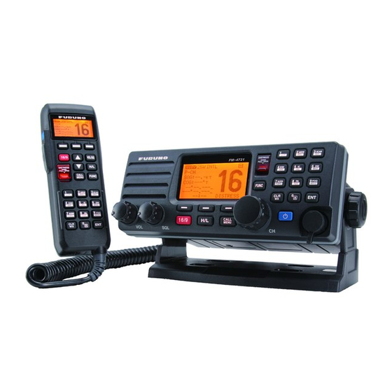
- Page 1 OPERATOR'S MANUAL MARINE VHF RADIOTELEPHONE FM-4721 MODEL www.furuno.com www.busse-yachtshop.de | info@busse-yachtshop.de...
-
Page 2: Important Notices
How to discard a used battery Some FURUNO products have a battery(ies). To see if your product has a battery, see the chapter on Maintenance. Follow the instructions below if a battery is used. Tape the + and - terminals of battery before disposal to prevent fire, heat generation caused by short circuit. -
Page 3: Safety Instructions
Electrical shock can result. power at the switchboard and contact a FURUNO service technician. Use the proper fuse. Use of the wrong fuse can cause fire or electrical shock. CAUTIO... - Page 4 Electrical shock, serious injury or fire can result if the power is not turned off or is Transceiver Unit 1.70 m 1.10 m applied while the equipment is being FM-4721 installed. Handset 0.70 m 0.45 m HS-4721 RADIO FREQUENCY RADIATION...
-
Page 5: Table Of Contents
TABLE OF CONTENTS FOREWORD ........................vii SYSTEM CONFIGURATION ..................viii GETTING STARTED....................1-1 1.1 Emergency Call (CH16) ..................... 1-1 1.2 How to Call Another Vessel (CH16 or CH9) .............. 1-1 1.3 How to Make Telephone Calls ................... 1-2 1.4 Channels 13 and 67 (USA channel group only)............1-2 OPERATION ......................2-1 2.1 Controls........................ - Page 6 TABLE OF CONTENTS 3.3.2 How to receive a DSC Distress Alert..............3-5 3.4 All Ships Call ......................3-6 3.4.1 How to transmit an All Ships call ..............3-6 3.4.2 How to receive an All Ships call ..............3-7 3.5 Individual Call ......................3-7 3.5.1 How to register DSC stations to the Individual Directory........3-7 3.5.2 How to select the Individual call reply method ..........3-8 3.5.3...
- Page 7 TABLE OF CONTENTS ANNEL UN T N SETUP................-1 5.1 CH Group ........................5-1 5.2 Scan Memory ......................5-1 5.3 Scan Type ........................5-2 5.4 Scan Resume......................5-2 5.5 Priority CH........................5-2 5.6 Weather Alert Setup....................5-3 5.7 Channel Naming ......................5-4 AT S SETUP......................
-
Page 8: Foreword
The FURUNO FM-4721 is a Marine VHF Radiotelephone designed for use in the frequency range of 156.025 to 163.275 MHz. The FM-4721 can be powered with 10.8 to 15.6 VDC power and has a switchable RF output power of 1 Watt or 25 Watts. -
Page 9: System Configuration
SYSTEM CONFIGURATION ANTENNA UNIT TRANSCEIVER UNIT FM-4721 Handset HS-4721 GPS Navigator External Speaker Loudhailer /PA Horn Handset HS-4721 Handheld MIC Optional, local supply Voice Scrambler FVP-42 equipment indicated 10.8 - 15.6 VDC (inside transceiver) with dashed lines. Bluetooth Adapter Unit BU-1... -
Page 10: Getting Started
10. If there is no answer, repeat the above procedure. If there is still no response, try another channel. Note: The FM-4721 has DSC Distress calling, which can send a distress call digitally to all ships with compatible DSC radios. Refer to chapter 3 “DIGITAL SELECTIVE CALLING". -
Page 11: How To Make Telephone Calls
1. GETTING STARTED ber of the other channel, and "over". Then switch to the new channel. When the new channel is not busy, call the vessel. After a transmission, say "over", and release the PTT (Push-To-Talk) switch on the microphone. When all communication with the vessel is completed, end the last trans- mission by stating your callsign and the word "out". -
Page 12: Operation
OPERATION Controls This section describes the controls of the Transceiver Unit (including the optional mi- crophone) and the Handset HS-4721. 2.1.1 Transceiver Unit Control Description • Adjust the audio volume level. Turn this knob clockwise to increase (Volume Control the audio volume level. Knob) •... - Page 13 2. OPERATION Select channels and select menu items. The S and T keys on the microphone can also be used to select channels and menu items. In the PA or Fog mode, change the output volume of the connected horn speaker. Power the transceiver on and off.
-
Page 14: Handset Hs-4721
21 m using three 7 m extension cables model CT-100. The Intercom feature can be used between the HS-4721 and the FM-4721. In addition, speaker wires are supplied at the panel mount of the routing cable to connect an ex- ternal speaker. - Page 15 2. OPERATION CALL Control Description Press and hold down this key to turn the transceiver and Handset on or (POWER) off. PTT switch Push this key to enable the transmitter. (Push-To-Talk Switch) DISTRESS Transmit a DSC Distress Alert. See chapter 3. Display Full dot matrix display.
-
Page 16: Reception
2. OPERATION Reception 1. After the transceiver has been installed, ensure that the power supply and anten- na are properly connected. 2. Press and hold the PWR key until the radio turns on. 3. Rotate the SQL knob fully counterclockwise. This state is known as "squelch off". 4. -
Page 17: Transmit Timeout Timer (Tot)
2. OPERATION Transmit Timeout Timer (TOT) When the PTT switch on the microphone is pressed continuously, transmit time is lim- ited to five minutes. This limits unintentional transmissions due to a stuck PTT switch. About 10 seconds before automatic transmitter shutdown, a warning beep sounds from the speaker(s). -
Page 18: Noaa Weather Channels
NOAA weather alert test NOAA tests the alert system every Wednesday between 11AM and 1PM UTC time. To test the FM-4721's NOAA weather feature (at the above-mentioned time) follow the procedure in paragraph 2.8.1 "NOAA weather alert" and confirm that the alert sounds. -
Page 19: Dual Watch (To Ch16)
The display alternately scans between CH16 and the channel that was selected in step 2. If a transmission is received on the channel selected in step 2, the FM-4721 starts dual watch on CH16. 4. To stop dual watch, press the FUNC key followed by the 6/DW key. -
Page 20: How To Program The Scan Memory
2. OPERATION 2.10.2 How to program the scan memory 1. Press and hold down the CALL/MENU key until the [Setup Menu] appears. 2. Rotate the CH knob to select [CH Function Setup]. 3. Press the [SELECT] soft key, then rotate the CH knob to select [Scan Memory CH] then press the [SELECT] soft key. -
Page 21: Priority Scanning P-Scan
2. OPERATION 2.1 .4 Priority scanning P-SCAN In the default setting, CH16 is set as the priority channel. (See section 5.5 for how to set priority channel.) ou may change the priority channel from 16 to another channel as shown below. 1. -
Page 22: How To Delete Preset Channels
HAI speaker. hen the Fog horn, ells or histle signal is not being outputted the FM-4721 listens back through the connected PA horn. Note: In the PA HAI or FO HORN mode, the FM-4721 receives communications on the last-selected VHF channel before entering into the PA HAI or FO HORN mode and receive DSC calls. -
Page 23: Fog Horn Mode
2. OPERATION 3. Rotate the CH knob to control the AF output level. The AF output level can be set from 0 to 30 watts. 4. Rotate the VOL knob to adjust the listenback volume. 5. To exit the PA HAIL mode, press the [QUIT] soft key or CLR/WX key. -
Page 24: Intercom Operation
HS-4721. 3. Press the PTT switch on the radio. [Talk] appears on the display. FM-4721’s PTT switch is pressed HS-4721’s PTT switch is pressed Note: A warning beep sounds when the radio’s PTT and the Handsets’ PTT are pushed at the same time. -
Page 25: How To Call On The Intercom
2.14 Bluetooth Operation (option) Installation of the optional BU-1 Bluetooth Adapter Unit enables the FM-4721 to send/ receive voice messages with a BH-2A Bluetooth Headset via wireless links. When the BH-2A is connected, [Bluetooth] appears in the [General Setup Menu]. -
Page 26: Operation
3. Press the PTT switch on the BH-2A to transmit. Release the PTT switch to return to receive. 4. The communication range between the BH-2A and FM-4721 is around 7 m (21 ft). If you move out of range, a beep sounds from the BH-2A to alert you. If you move back into range, the BH-2A beeps to alert you that you are back within range. -
Page 27: Battery Saver
Voice Scrambler (option) The optional Voice Scrambler FVP-42 is a 32-code voice scrambler (VS) that installs in the transceiver, and provides private communications with other FM-4721 equipped with the FVP-42. Contact your dealer to have a FVP-42 installed. 1. Rotate the CH knob to select the channel to scramble. -
Page 28: Digital Selective Calling
DIGITAL SELECTIVE CALLING General NOTICE This radio is designed to generate a digital maritime distress and safety call to facilitate search and rescue. To be effective as a safety device, this equipment must be used only within communication range of a shore-based VHF marine channel 70 distress and safety watch system. -
Page 29: Dsc Distress Alert
1 to 2. DSC Distress Alert The FM-4721 is capable of transmitting and receiving DSC distress alerts. The FM- 4721 may be connected to a GPS receiver to also transmit the latitude and longitude position of the vessel together with the DSC distress alert. - Page 30 [OK] soft key. How to transmit a DSC Distress Alert with nature of distress specified The FM-4721 is capable of transmitting a DSC Distress Alert with the following "Nature of Distress" categories: Undesignated, Fire, Flooding, Collision, Grounding, Capsiz- ing, Sinking, Adrift, Abandoning, Piracy, and MOB (Man Overboard).
- Page 31 3. DI ITA SE ECTIVE CA Received RE A AC : Relay acknowledgment signal is received from another vessel or coast station. 9. Press the PTT switch and state your name, vessel name, number of persons on board and the distress situation, then say over. ait for a reply from the acknowl- edging ship.
-
Page 32: How To Receive A Dsc Distress Alert
After a DSC Distress Alert is transmitted, the DSC Distress Alert is repeated in 3.5 - 4.5-minute intervals until the call is canceled by the user or until the radio is turned on and off again. The FM-4721 has a provision to suspend (Pause) the retransmitting of the distress call. -
Page 33: All Ships Call
3. DI ITA SE ECTIVE CA All Ships Call The All Ships call function establishes contact with DSC-equipped vessels without having their MMSI in the directory. Also, priority for the call can be designated as ur- gency or safety. rgency Call: This type of call is used when a vessel may not truly be in distress, but has a potential problem that may lead to a distress situation. -
Page 34: How To Receive An All Ships Call
3. DIGITAL SELECTIVE CALLING 3.4.2 How to receive an All Ships call 1. When an All Ships call is received, an emergency alarm sounds. The display shows the MMSI of the vessel transmitting the All Ships call and the radio changes to the requested channel after 10 seconds. -
Page 35: How To Select The Individual Call Reply Method
3. DIGITAL SELECTIVE CALLING 5. Enter the first letter of the name of the vessel or person you want to reference in the directory. Example: Press the 8/PA key repeatedly to toggle among the seven available characters associated with that key: 8 → T → U → V → t → u → v → 8... 6. -
Page 36: How To Select The Individual Call Acknowledge Method
3. DIGITAL SELECTIVE CALLING 3.5.3 How to select the Individual call acknowledge method The radio can be setup to transmit a reply automatically (default setting) or set so the radio does not reply to an Individual call. 1. Press and hold down the CALL/MENU key until the [Setup Menu] appears. 2. -
Page 37: How To Transmit An Individual Call
3. DI ITA SE ECTIVE CA 3. . How to transmit an ndi id al call The Individual call lets you contact a vessel that has a DSC radio. This feature is sim- ilar to calling a vessel on CH16 and requesting to go to another channel. Transmit to essel registered in the ndi id al Directory 1. - Page 38 3. DI ITA SE ECTIVE CA 5. After you have entered the MMSI number, press and hold the SE ECT soft key. 6. Rotate the CH knob to select the operating channel you want to communicate on then press the SE ECT soft key.
- Page 39 3. DI ITA SE ECTIVE CA Man al reply hen an Individual call is received, the Individual call ringing alarm sounds. Push any key to stop the alarm. The display shows Individual Call the MMSI of the vessel calling and three soft keys: ACCEPT , PA SE , and IT .
-
Page 40: Dsc Log
DSC log feature is similar to an answering machine where calls are recorded for re- view. A icon appears in the log to indicate unread received call. The FM-4721 can store the latest 24 transmitted calls, the latest 27 distress calls, and the latest 64 other calls ([Individual], [Group], [All Ship], etc.). -
Page 41: How To Delete Calls From A Log
3. DIGITAL SELECTIVE CALLING 3.6.4 How to delete calls from a log 1. Press the CALL/MENU key to show the [DSC Menu]. 2. Rotate the CH knob to select [DSC Log] menu then press the [SELECT] soft key. 3. Rotate the CH knob to select [LOG Delete] menu then press the [SELECT] soft key. - Page 42 MMSI. • The first digit of a Group call MMSI is always set to "0" as required by international regulations. All FURUNO radios automatically have “0” as the first digit in a Group call MMSI. • The USCG recommends programming the MID of a ship MMSI into the second, third and fourth digits of the Group call MMSI as it denotes the area the ship is lo- cated.
-
Page 43: How To Transmit A Group Call
3. DI ITA SE ECTIVE CA 3.7.2 How to transmit a ro p call Transmit ro p call to gro p registered in the ro p Directory 1. Press the CALL/M N key to show the DSC Menu . 2. Rotate the CH knob to select roup then press the SE ECT soft key to show the roup Directory... -
Page 44: How To Receive A Group Call
3.7.3 How to recei e a ro p call hen a roup call is received, the FM-4721 releases the ringer alarm and the radio automatically switches to the requested channel. 2. Press any key to stop the alarm. -
Page 45: Position Request Call
Advancements in DSC have made it possible to poll the location of another vessel and show the position of that vessel on the display of the FM-4721. FURUNO has taken this feature one step further. If a compatible GPS chart plotter is connected to the FM- 4721, the polled position of the vessel is shown on the display of the GPS chart plotter making it easy to navigate to the location of the polled vessel. -
Page 46: How To Transmit A Position Request Call To Another Vessel
[SELECT] soft key. 5. Press the [YES] soft key to transmit the position re- quest DSC call. When the FM-4721 receives the posi- tion from the polled vessel it appears on the display and is also transferred and shown on a GPS chart plot- ter (if connected to the FM-4721). -
Page 47: When You Receive A Position Request Call
A Position Report call transmits your position to another vessel. Your vessel must have an operating GPS receiver connected to the FM-4721 to transmit your position. The MMSI of the vessel can be one you have programmed, or entered manually. -
Page 48: How To Transmit A Position Report Call
3. DIGITAL SELECTIVE CALLING 3.9.2 How to transmit a Position Report call Transmit your position to vessel registered in the Individual Directory 1. Press the CALL/MENU key to show the [DSC Menu]. ROUTINE 2. Rotate the CH knob to select [POS Report] then press Safety the [SELECT] soft key. -
Page 49: When You Receive A Position Report Call
3. DI ITA SE ECTIVE CA 3.9.3 hen yo recei e a Position Report call hen another vessel transmits its position to the FM-4721 the following occurs: 1. The ringer sounds and NMEA sentences DSC, DSE are outputted to a PS chart plotter (if connected to the FM-4721). -
Page 50: Auto Dsc Polling
3. DI ITA SE ECTIVE CA A to DSC Polling The FM-4721 has the capability to automatically track four stations programmed into the individual directory. The following procedure allows the time interval between position requests to be set- 1. Press and hold down the CALL/M N key until the Setup Menu appears. -
Page 51: Enable/Disable Auto Dsc Polling
3. DIGITAL SELECTIVE CALLING 3.10.2 Enable/Disable auto DSC polling 1. Press the CALL/MENU key to show the [DSC Menu]. 2. Rotate the CH knob to select [Auto POS Polling] then press the [SELECT] soft key. 3. Rotate the CH knob to select [Activation] then press the [SELECT] soft key. -
Page 52: Dsc Test
3. DIGITAL SELECTIVE CALLING 3.12 DSC Test This function contacts another DSC-equipped vessel to test your DSC radio for proper operation. To use this feature, the radio that you transmit the test call to must have the DSC test feature. To do the DSC test, enter the MMSI of another vessel. -
Page 53: How To Make A Dsc Test Call By Manually Entering Mmsi
3. DIGITAL SELECTIVE CALLING 3.12.2 How to make a DSC test call by manually entering MMSI 1. Press the CALL/MENU key to show the [DSC Menu]. 2. Rotate the CH knob to select [DSC Test] then press the [SELECT] soft key. 3. -
Page 54: General Setup
GENERAL SETUP The procedures in this chapter can also be done from the HS-4721 Handset. Display Contrast The display contrast can be adjusted to suit environmental conditions. 1. Press and hold down the CALL/MENU key until the [Setup Menu] appears. 2. -
Page 55: Time Area
4. GENERAL SETUP Time Area Time can be shown in UTC time or local time with the offset. 1. Press and hold down the CALL/MENU key until the [Setup Menu] appears. 2. Select [General Setup] with the CH knob then press the [SELECT] soft key. -
Page 56: Cog Display Format
4. GENERAL SETUP COG Display Format GPS COG (Course Over Ground) can be shown in True or Magnetic. Note: A GPS must be connected to the radio to be able to show COG. 1. Press and hold down the CALL/MENU key until the [Setup Menu] appears. 2. -
Page 57: Key Beep
4. GENERAL SETUP Key Beep Set the level of the key beep that is emitted when a key is pressed. 1. Press and hold down the CALL/MENU key until the [Setup Menu] appears. 2. Select [General Setup] with the CH knob then press the [SELECT] soft key. -
Page 58: How To Name The Radio Or Handset
4. GENERAL SETUP 3. Rotate the CH knob to select [Fog Frequency] then press the [SELECT] soft key 4. Rotate the CH knob to select the desired tone frequen- cy then press the [ENT] soft key to store the selected setting. -
Page 59: Soft Keys
4. GENERAL SETUP 4.12 Soft Keys This section shows you how to set up the soft keys. You can select the number of soft keys to use, program the soft keys and select how long to show the soft key icon after a soft key is pressed. -
Page 60: Handset Hs-4721
IT soft key several times to return to handset operation. 4.13 Calendar Set p The FM-4721 has a built in clock to remember date, time, latitude and longitude. A PS receiver not only provides position data but also updates the calendar. Refer to section .5 Accessory Cable. - Page 61 ENERA SET P Example 1: If you are East of TC time, add the offset to your time. City Rome Offset Time (convert local time to 24 hour) 4:00PM (12hour) or 16:00 (24hour) Calculate 24hour local - Offset (East of TC) 16:00 - 01:00 15:00 Example 2: If you are west of TC time, subtract the offset from your time.
-
Page 62: How To Set The Timeouts
4. GENERAL SETUP 4.14 How to Set the Timeouts A timeout determines the number of minutes the radio should keep a given screen dis- played before it restores the standby display, if no radio operation is detected. There are three types of screens for which you can set a timeout: menu, DSC non-distress, and DSC distress. - Page 63 4. GENERAL SETUP This page is intentionally left blank. 4-10 www.busse-yachtshop.de | info@busse-yachtshop.de...
-
Page 64: Ch Group
CHANNEL FUNCTION SETUP CH Group Select the channel group among USA, Canada, and International. 1. Press and hold down the CALL/MENU key until the [Setup Menu] appears. 2. Rotate the CH knob to select [CH FUNCTION Setup] then press the [SELECT] soft key. 3. -
Page 65: Scan Type
5. Press the [QUIT] soft key several times to return to radio operation. Scan Resume Set the time the FM-4721 waits after a transmission ends until the radio resumes channel scanning. 1. Press and hold down the CALL/MENU key until the [Setup Menu] appears. -
Page 66: Weather Alert Setup
5. CHANNEL FUNCTION SETUP Weather Alert Setup In the event of extreme weather disturbances, such as storms and hurricanes, the NOAA (National Oceanic and Atmospheric Administration) sends a weather alert ac- companied by a 1050 Hz tone and subsequent weather report on one of the NOAA weather channels. -
Page 67: Channel Naming
5. CHANNEL FUNCTION SETUP Channel Naming When the radio mode is in use, the display shows a name under the channel number selected. This is name of the current channel. You can customize channel names as follows: 1. Press and hold down the CALL/MENU key until the [Setup Menu] appears. 2. -
Page 68: Atis Code Programming
ATIS SETUP The FM-4721 supports the ATIS (Automatic Transmitter Identification System) used in Inland waterways in Europe. When enabled, the ATIS mode transmits a unique ATIS code each time the microphone's PTT switch is released at the end of a trans- mission. -
Page 69: Atis Channel Group
6. ATIS SETUP ATIS Channel Group The FM-4721 has the capability to turn on and off the ATIS feature for each channel Group call but operator must select only INTL channel group. 1. Press and hold down the CALL/MENU key until the [Setup Menu] appears. -
Page 70: General Maintenance
• The supply voltage range to the transceiver must be within 10.8 - 15.6 VDC. • Use only FURUNO-approved accessories and replacement parts. • Wipe the LCD carefully to prevent scratching, using tissue paper and an LCD clean- er. -
Page 71: Troubleshooting Chart
7. MAINTENANCE, TROUBLESHOOTING Troubleshooting Chart Symptom Probable cause Remedy Transceiver cannot No DC voltage to the transceiv- • Check the 10.8 - 15.6 VDC battery con- be powered. er, or blown fuse nections and the fuse. • The (power) button needs to be pressed and held to turn the radio on. -
Page 72: How To Replace The Fuse
7. MAINTENANCE, TROUBLESHOOTING How to Replace the Fuse If the power cannot be turned on, the fuse may have blown. To take out the fuse from the fuse holder on the power cable, hold both ends of the fuse holder and pull the fuse holder apart without bending the fuse holder. -
Page 73: Daily Test
7. MAINTENANCE, TROUBLESHOOTING Daily Test The daily test is an FSK loop test that sends a dummy DSC message to check if the message is sent and received correctly. 1. Long push the CALL/MENU key to show the [Setup] Menu. 2. -
Page 74: Transceiver Unit
INSTALLATION Transceiver Unit The transceiver unit can be mounted on a desktop or overhead, or flush mounted in a panel. Choose a mounting location considering the points mentioned below. • Follow the compass safety distance shown in the safety Instructions to avoid any interference to the compass from the speaker magnet in the transceiver. -
Page 75: Flush Mount (Option)
8. INSTALLATION 8.1.2 Flush mount (option) Requires the MMB-84 flush mount bracket. 1. Make a rectangular template for the flush mount measuring 65×161 mm. 2. Use the template to mark the location where the rectangular hole is to be cut. Con- firm that the space behind the dash or panel is deep enough to accommodate the transceiver (at least 177 mm deep). -
Page 76: Electrical Connections
8. INSTALLATION Coaxial Cable The VHF antenna is connected to the transceiver by means of a coaxial cable - a shielded transmission line. Coaxial cable is specified by its diameter and construction. For runs less than 6 m, RG-58/U, which is approx. 1/4 inch in diameter, is a good choice. - Page 77 . INSTA ATION 4 21 How to attach errite core To suppress RF interference that can cause abnormal operation of the transceiver, at- tach the supplied three ferrite cores to the Accessory Cable/Power Cable and Exten- sion Cable, then snap its two halves together, as shown in the illustration below. Attach each ferrite core as close as possible to the transceiver body, as shown.
-
Page 78: Accessory Cable
Shield of cable is not attached on PA Speaker end. 2-conductor shielded Bare PA Speaker Connect the bare wire from the FM-4721 to one wire and to the shielded. Make Red and bare connections as short as possible. www.busse-yachtshop.de | info@busse-yachtshop.de... -
Page 79: Handset Hs-4721
Handset HS-4721 The Handset remotely controls the Radio, DSC, and PA/Fog functions. In addition, the FM-4721 can operate as a full function intercom system between the HS-4721 and the FM-4721. 1. Connect the Extension Cable to the Handset connector (eight pin) on the rear panel, then tighten the Nut (see illustration on the next page). - Page 80 . INSTA ATION 3. Drill the four screw holes (approx. 2 mm in diameter) on the wall, then fasten the Mounting racket to the wall using four self-tapping screws. 4. Put the Rubber Cap onto the Nut. The installation is now complete. The extension cable can be cut and spliced, however care needs to be taken when reconnecting the wires to ensure watertight integrity.
-
Page 81: How To Use An E Ternal Speaker
How to set time offset to show local time The FM-4721 is set at the factory to show GPS satellite time or UTC time when an optional GPS receiver is connected. If you prefer to use local time, enter the time dif- ference between your local time and UTC. -
Page 82: How To Show Local Time Or Utc Time
8. INSTALLATION 8.7.2 How to show local time or UTC time You can show UTC time or local time. 1. Press and hold down the CALL/MENU key until the [Setup Menu] appears. 2. Select [General Setup] with the CH knob then press the [SELECT] soft key. 3. -
Page 83: Optional Equipment
8. INSTALLATION Optional Equipment 8.8.1 Bluetooth Adapter Unit BU-1 The BU-1 installs inside the transceiver and enables bluetooth compatible devices such as a bluetooth headset. Before starting the installation, turn the transceiver off and disconnect all cables from the transceiver. Touch a metal place to discharge any static electricity from your body. 1. - Page 84 Voice Scrambler FVP-42 The Voice Scrambler installs inside the transceiver and provides private communica- tions with an FM-4721 equipped with the FVP-42. Before starting the installation, turn the transceiver off and disconnect all cables from the transceiver. Touch a metal place to discharge any static electricity from your body.
- Page 85 8. INSTALLATION 5. Fasten the Voice Scrambler circuit board to the transceiver with the screws unfas- tened at step 4. Plug in the connector from the Voice Scrambler circuit board where the dummy connector was connected. Plug in connector from circuit board here.
- Page 86 APPENDIX 1 CHANNEL ASSIGN- MENTS, MENU TREE Channel Assignments This chapter provides the VHF Marine Channel assignments for U.S.A. and International use. Be- low are listed some data about the charts. 1. Channels indicated as VTS are part of the U.S. Coast Guard's Vessel Traffic System. 2.
- Page 87 APPENDIX 1 CHANNEL ASSIGNMENTS, MENU TREE Channel use 156.200 Pacific coast: Coast Guard, East Coast: Commercial fishing 156.250 160.850 Public Correspondence (Marine Operator), Port operation, ship movement 156.250 Port operation. VTS in Seattle 156.300 Inter-ship Safety 156.350 160.950 Public Correspondence (Marine Operator), Port operation, ship movement 156.350 Commercial...
- Page 88 APPENDIX 1 CHANNEL ASSIGNMENTS, MENU TREE Channel use 156.125 160.725 Public Correspondence (Marine Operator), Port operation, ship movement 156.125 Public Coast: Coast Guard; East Coast: commercial fishing only 156.175 160.775 Public Correspondence (Marine Operator), Port operation, ship movement 156.175 Port Operation and Commercial. VTS in selected areas.
- Page 89 APPENDIX 1 CHANNEL ASSIGNMENTS, MENU TREE Channel use 157.025 Commercial 157.075 161.675 Port operation, ship movement 81A* 157.075 U.S. Government Only -Environmental pro- tection operations. 157.075 Canadian Coast Guard Only 157.125 161.725 Public Correspondence (Marine Operator), Port operation, ship movement 82A* 157.125 U.S.
- Page 90 APPENDIX 1 CHANNEL ASSIGNMENTS, MENU TREE Menu Tree (default settings shown in bold italic) DSC menu CALL/ Individual (Select, New ID) MENU Menu Group (Select, Manual) All Ships (Safety, Urgency) POS Request (Select, Manual) POS Report (Select, Manual) Distress Alert MSG (Nature, POS/TM) Auto POS Polling (Activation, Select Address) DSC Log Transmitted Log...
- Page 91 APPENDIX 1 CHANNEL ASSIGNMENTS, MENU TREE (Continued from previous page) CH Group (Group 1: USA, Group 2: INTL, Group 3: CAN) Function Scan Memory CH (Add, delete channels in scan memory.) Setup Scan Type (Priority Scan, Memory Scan) Scan Resume (1 - 5sec, Off, 2sec) Priority CH (Specify priority channel, 16 is default.) WX Alert (On, Off) Select Channel...
- Page 92 FURUNO FM-4721 SP C MAR N H RAD T L PH N M-4721 N RAL Channels SA, International and Canadian Input voltage 12.0 VDC Operating voltage range 10. to 15.6 VDC Current drain Standby: 0.5 A, Receive: 1.5 A, Transmit: 6.0 A (Hi), 2.5 A ( o)
- Page 93 FURUNO FM-4721 This page is intentionally left blank. SP - 2 E56 4S01E 110415 www.busse-yachtshop.de | info@busse-yachtshop.de...
- Page 94 INDEX Numerics transmitting, nature not specified .... 3-2 transmitting, nature specified ....3-3 0 key............2-2 transmitting, with manual position ... 3-4 16/9 key............. 2-1 DISTRESS key......2-2 2/MEM key ..........2-2 DSC distress call log ....... 3-13 3/SCAN key..........2-2 DSC log 4/DIM key ...........
- Page 95 INDEX Key beep ............4-4 Telephone call..........1-2 Time notation ..........4-2 Time offset ..........4-1 Local time...........4-2 Timeout ............4-9 Transmission..........2-5 Maintenance ..........7-1 Transmit timeout timer .......2-6 Memory clear ..........7-3 Transmitted DSC call log ......3-13 Memory scanning........2-9 Troubleshooting .........7-2 Microprocessor reset .........7-3 MMSI Units of measurement ........4-2 description..........3-1 UTC time ............4-2 entry of .............3-1...
- Page 96 www.busse-yachtshop.de | info@busse-yachtshop.de...
- Page 97 (Elemental Chlorine Free) The paper used in this manual is elemental chlorine free. F U R U N O A u t h o r i z e d D i s t r i b u t o r D e a l e r 9 - 5 2 , A s h i h a r a - c h o , N i s h i n o m i y a , 6 6 2 - 8 5 8 0 , J A PA N Te l e p h o n e :...
Need help?
Do you have a question about the FM-4721 and is the answer not in the manual?
Questions and answers