Toshiba B-SV4T SERIES Owner's Manual
Hide thumbs
Also See for B-SV4T SERIES:
- Manual (71 pages) ,
- Safety precautions (2 pages) ,
- Instructions (3 pages)

Related Manuals for Toshiba B-SV4T SERIES


Summary of Contents for Toshiba B-SV4T SERIES
- Page 1 TOSHIBA Barcode Printer B-SV4T SERIES Owner’s Manual Mode d’emploi Bedienungsanleitung Manual de instrucciones Gebruikershandleiding Manuale Utente Manual do Utilizador...
- Page 2 TOSHIBA Barcode Printer B-SV4T SERIES Owner’s Manual...
- Page 3 “Cet appareil numérique de la classe B respecte toutes les exigences du Règlement sur le matériel brouilleur du Canada.” (for CANADA only) The EA10953 AC adapter should be exclusively used for the B-SV4T Series printer. The B-SV4T Series printer must be powered by the EA10953 AC adapter. Waste Recycling information for users:...
-
Page 4: Safety Summary
Do not attempt to effect repairs or modifications to this equipment. If a fault occurs that cannot be rectified using the procedures described in this manual, turn off the power, unplug the machine, then contact your authorised TOSHIBA TEC representative for assistance. Meanings of Each Symbol This symbol indicates warning items (including cautions). - Page 5 • Utilize our maintenance services. After purchasing the machine, contact your authorised TOSHIBA TEC representative for assistance once a year to have the inside of the machine cleaned. Otherwise, dust will build up inside the machines and may cause a fire or a malfunction. Cleaning is particularly effective before humid rainy seasons.
-
Page 6: Table Of Contents
ENGLISH VERSION EO1-33062 TABLE OF CONTENTS Page PRODUCT OVERVIEW......................E1-1 Introduction........................E1-1 Features ........................E1-1 Unpacking........................E1-1 Accessories ........................E1-1 Appearance ........................E1-3 1.5.1 Dimensions.........................E1-3 1.5.2 Front View ........................E1-3 1.5.3 Rear View ........................E1-3 1.5.4 Interior ........................E1-4 1.5.5 Button and Indicator Lamp ..................E1-4 PRINTER SETUP ........................ -
Page 7: English Version
INDEX CAUTION! 1. This manual may not be copied in whole or in part without prior written permission of TOSHIBA TEC. 2. The contents of this manual may be changed without notification. 3. Please refer to your local Authorized Service representative with regard to any queries you may have in... -
Page 8: Product Overview
1. Unpack the printer. 2. Check for damage or scratches on the printer. However, please note that TOSHIBA TEC shall have no liability for any damage of any kind sustained during transportation of the product. 3. Keep the cartons and pads for future transportation of the printer... - Page 9 1.4 Accessories When purchasing the power cord Since the power cord set is not enclosed in this unit, please purchase an approved one that meets the following standard from your Authorised TOSHIBA TEC representative. (As of September 2004) Certification Certification...
-
Page 10: Appearance
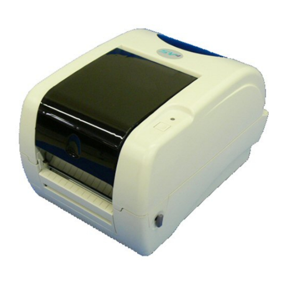
1. PRODUCT OVERVIEW ENGLISH VERSION EO1-33062 1.5 Appearance The names of the parts or units introduced in this section are used in the 1.5 Appearance following chapters. 1.5.1 Dimensions 314 (12.4) 213 (8.4) (7.4) Dimensions in mm (inches) 1.5.2 Front View Ribbon Access Cover Indicator Lamp Top Cover... -
Page 11: Interior
1. PRODUCT OVERVIEW ENGLISH VERSION EO1-33062 1.5 Appearance 1.5.4 Interior WARNING! Ribbon Access Cover Do not touch the print head or around it just after printing. You may get burned as the Rear Hub print head becomes very hot during printing. Front Hub Print Head Cover Open... -
Page 12: Printer Setup
• For best results, and longer printer life, use only TOSHIBA TEC recommended media and ribbon. (Refer to the Supply Manual.) • Store the media and ribbon in accordance with the specifications. -
Page 13: Procedure Before Operation
10. Install the Printer Drivers in the host computer. (Refer to the Printer commands. For details, please Driver in the CD-ROM.) contact your TOSHIBA TEC reseller. 2.3 Turning the Printer When the printer is connected to a host computer it is good practice to... -
Page 14: Turning Off The Printer
2. PRINTER SETUP ENGLISH VERSION EO1-33062 2.4 Connecting the Cables to the Printer 1. Before turning off the printer power switch verify that the Indicator 2.3.2 Turning OFF the Lamp is illuminated in green, not flashing. Printer 2. To turn OFF the printer power press the power switch as shown in the diagram below. -
Page 15: Connecting The Power Adapter And The Power Cord
1-2. 2. The EA10953 AC adapter should be exclusively used for the B-SV4T Series printer. The B-SV4T Series printer must be powered by the 3. Insert the Power Adapter connector into the Power Jack on the rear of EA10953 AC adapter. -
Page 16: Opening/Closing The Top Cover
2. PRINTER SETUP ENGLISH VERSION EO1-33062 2.6 Opening/Closing the Top Cover 2.6 Opening/Closing the When opening or closing the Top Cover, please be sure to follow the instructions below. Top Cover To open the Top Cover: WARNING! 1. To avoid injury, be careful 1. - Page 17 2. PRINTER SETUP ENGLISH VERSION EO1-33062 2.6 Opening/Closing the Top Cover 2.6 Opening/Closing the To hold the Top Cover at Position 2, first open the Top Cover until the Top Cover Support goes over Position 2 ( ), then close the Top Cover a Top Cover (Cont.) little ( ) to secure the Top Cover Support.
-
Page 18: Loading The Media
2. PRINTER SETUP ENGLISH VERSION EO1-33062 2.7 Loading the Media 2.7 Loading the Media This section describes in detail how to load a media roll. 1. Turn OFF the printer. 2. Turn the Cover Open Levers frontward, and open the Top Cover. WARNING! 1. - Page 19 2. PRINTER SETUP ENGLISH VERSION EO1-33062 2.7 Loading the Media 6. Insert the both ends of the Media Shaft into the slots of the printer to 2.7 Loading the Media place the Media Holder Ass’y into the printer. Make sure that the (Cont.) media feeds from the top, as shown below.
- Page 20 2. PRINTER SETUP ENGLISH VERSION EO1-33062 2.7 Loading the Media 11. After loading the media, manually set the Media Sensor to the 2.7 Loading the Media correct position. (Cont.) The Feed Gap Sensor is included in the right Media Guide. Position of the Feed Gap Sensor can be set by fitting the Media Guides to the media ends.
- Page 21 2. PRINTER SETUP ENGLISH VERSION EO1-33062 2.7 Loading the Media Strip mode (Option): 2.7 Loading the Media (Cont.) When issued in the strip mode, labels are automatically removed from the backing paper each time a label is printed. • How to set the media When issuing labels in the strip mode, set the label in the following procedure: 1.
- Page 22 2. PRINTER SETUP ENGLISH VERSION EO1-33062 2.7 Loading the Media Cut mode (Option): 2.7 Loading the Media (Cont.) When the Cutter is installed, the media is automatically cut. After loading the media as described on the previous pages, insert the leading edge of the media through the Media Outlet of the Cutter Cover.
- Page 23 2. PRINTER SETUP ENGLISH VERSION EO1-33062 2.7 Loading the Media When a media roll has an outside diameter exceeding 127 mm (5”) or an 2.7 Loading the Media inner core diameter of 38.1 mm (1.5”), the optional External Media Roll (Cont.) Hanger is required.
-
Page 24: Loading The Ribbon
2. PRINTER SETUP ENGLISH VERSION EO1-33062 2.8 Loading the Ribbon 2.8 Loading the Ribbon When the printer is turned on, it automatically detects whether a ribbon is installed or not and switches the printing method between thermal transfer or direct thermal. If the printer does not detect a ribbon (direct WARNING! thermal mode), the motor that drives the ribbon spindles will be turned 1. - Page 25 2. PRINTER SETUP ENGLISH VERSION EO1-33062 2.8 Loading the Ribbon 2.8 Loading the Ribbon 5. Pull the leader tape of the ribbon downward, and feed it under the Print Head. (Cont.) 6. Attach the leader tape to the Paper Core with adhesive tape. NOTES: 1.
-
Page 26: Media Sensor Calibration, Self Print Test, And Dump Mode Utilities
2. PRINTER SETUP ENGLISH VERSION EO1-33062 2.9 Media Sensor Calibration, Self Print Test, and Dump Mode Utilities This utility is used to calibrate the sensitivity of the Feed Gap/Black 2.9 Media Sensor Mark Sensor. Calibration, Self Print It is necessary to set the media sensors after the media is changed to Test, and Dump Mode different type. - Page 27 2. PRINTER SETUP ENGLISH VERSION EO1-33062 2.9 Media Sensor Calibration, Self Print Test, and Dump Mode Utilities Print test label sample 2.9.2 Self Print Test and Dump Mode (Cont.) PRINTER INFO. PROGRAM VERSION VX.XX XXXX NOTE: TONE ADJUST The following commands should FEED ADJUST +XX.Xmm not affect the test print issue.
-
Page 28: Maintenance
3. Do not touch the print head Print Head Element element with bare hands, Print Head Cleaner (Positioned at the as static may damage the print head edge) print head. NOTE: Please purchase the Print Head Cleaner from the authorised TOSHIBA TEC service representative. E3- 1... -
Page 29: Platen/Sensors
3. MAINTENANCE ENGLISH VERSION EO1-33062 3.1 Cleaning 1. Wipe the Platen with a soft cloth moistened with absolute alcohol. 3.1.2 Platen/Sensors 2. Remove dust or paper particles from the Black Mark Sensor, Feed Gap Sensor, and Ribbon Sensor using an air blower. Feed Gap Sensor Black Mark Sensor Platen... -
Page 30: Care/Handling Of The Media And Ribbon
3. MAINTENANCE ENGLISH VERSION EO1-33062 3.2 Care/Handling of the Media and Ribbon • Do not store media or ribbons for longer than the manufacturer’s 3.2 Care/Handling of the recommended shelf life Media and Ribbon • Store media rolls on the flat end. Do not store them on the curved CAUTION! sides as this might flatten that side causing erratic media advance and poor print quality. -
Page 31: Troubleshooting
WARNING! If a problem cannot be solved by taking actions described in this chapter, do not attempt to repair the printer. Turn off and unplug the printer. Then contact an authorised TOSHIBA TEC service representative for assistance. 4.1 Troubleshooting Guide... -
Page 32: Appendix 1 Specifications
APPENDIX 1 SPECIFICATIONS ENGLISH VERSION EO1-33062 A1.1 Printer APPENDIX 1 SPECIFICATIONS Appendix 1 describes the printer specifications and supplies for use on the B-SV4T printer. A1.1 Printer The following are the printer specifications. Item Specifications Supply voltage AC100 to 240V, 50/60 Hz... -
Page 33: A1.2 Options
The above options are available from your nearest TOSHIBA TEC representative or TOSHIBA TEC Head Quarters. A1.3 Media Please make sure that the media to be used is approved by TOSHIBA TEC. The warranties do not apply to problems caused by using media that is not approved by TOSHIBA TEC. -
Page 34: A1.3.2 Detection Area Of The Transmissive Sensor
25.4, 38.1, or 76.2 (1, 1.5, or 3) NOTES: 1. To ensure print quality and print head life use only TOSHIBA TEC approved media. 2. When using a media roll of 76.2-mm (3”) inner core diameter, the 3”-Diameter Media Shaft included in the optional External Media Roll Hanger is required. -
Page 35: A1.3.3 Detection Area Of The Reflective Sensor
APPENDIX 1 SPECIFICATIONS ENGLISH VERSION EO1-33062 A1.3 Media A1.3.3 Detection Area of the Reflective Sensor The Reflective Sensor is movable within the full range of the media width. The reflection factor of the Black Mark must be 10% or lower with a waveform length of 950 nm. The Reflective Sensor should be aligned with the centre of the Black Mark. -
Page 36: A1.3.4 Effective Print Area
5. Line weight should be 3 to 12 dots. A1.4 Ribbon Please make sure that the ribbon being used is approved by TOSHIBA TEC. The warranty does not apply to any problem caused by using non-approved ribbons. For information regarding TOSHIBA TEC approved ribbon, please contact a TOSHIBA TEC service representative. -
Page 37: Appendix 2 Interface
APPENDIX 2 INTERFACE ENGLISH VERSION EO1-33062 APPENDIX 2 INTERFACE APPENDIX 2 INTERFACE Interface Cables To prevent radiation and reception of electrical noise, the interface cables must meet the following requirements: • Fully shielded and fitted with metal or metallized connector housings. •... - Page 38 GLOSSARIES ENGLISH VERSION EO1-33062 GLOSSARIES GLOSSARIES Bar code A code which represents alphanumeric characters Distance from the bottom of one label to the top of by using a series of black and white stripes in the next label. different widths. Bar codes are used in various industrial fields: Manufacturing,...
- Page 39 GLOSSARIES ENGLISH VERSION EO1-33062 GLOSSARIES Supply Media and ribbon A type of media having no adhesive backing but black marks to indicate the print area. Usually tags are made of cardboard or other durable material. Thermal print head A print head using thermal transfer or thermal direct printing method.
- Page 40 INDEX ENGLISH VERSION EO1-33062 INDEX INDEX Backing paper 2-10, A1-3 Keyboard display unit A1-2 Bar code A1-1 Batch mode 2-6 Black mark 2-9, 2-15, A1-2, A1-4 Label 2-10, A1-2 Black mark length A1-3 LAN A1-1 Black mark sensor 1-4, 2-8, 2-9, 2-15, 3-2 LAN adapter A1-2 Centronics 1-3, 2-2, 2-3, A1-1 Media 2-7, 3-3, A1-2...
- Page 41 INDEX ENGLISH VERSION EO1-33062 INDEX Serial interface 1-3, 2-3, A1-1 Strip mode 2-10, A1-3 Supply voltage A1-1 Tag paper A1-2 Thermal transfer A1-1 Top cover support 1-4, 2-5, 2-6 3”-diameter media shaft 2-12, A1-3 Two-dimensional code A1-1 USB interface 1-3, 2-3, A1-1 Weight A1-1...
- Page 42 EO1-33062...
Need help?
Do you have a question about the B-SV4T SERIES and is the answer not in the manual?
Questions and answers