
Related Manuals for Piazzetta 760T HT/C


Summary of Contents for Piazzetta 760T HT/C
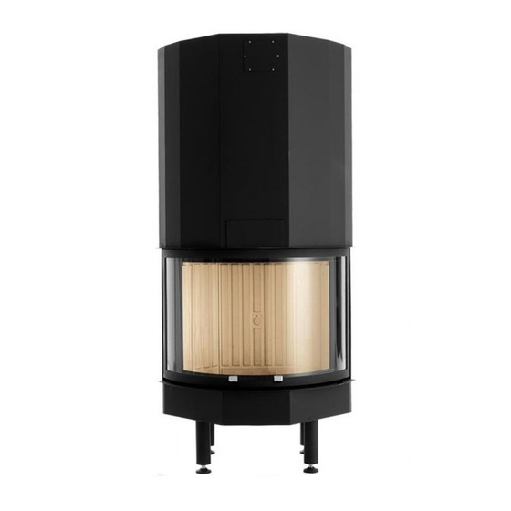
- Page 1 MONOBLOCCO FIREPLACE 760T HT/C ISTRUZIONI PER L’INSTALLAZIONE, L’USO E LA MANUTENZIONE INSTRUCTIONS FOR INSTALLATION, USE AND MAINTENANCE...
- Page 2 Questo documento è di proprietà del Gruppo Piazzetta S.p.A.; non può essere divulgato totalmente o in parte a terzi senza autorizzazione scritta del Gruppo Piazzetta S.p.A. Il Gruppo Piazzetta S.p.A. si riserva i diritti a rigore di legge.
-
Page 3: Table Of Contents
CARATTERISTICHE E DATI TECNICI DT2011094-00 Descrizione dell’apparecchio DT2010626-00 Accessori e dotazioni DT2011095-00 Caratteristiche DT2011096-00 Dati di identificazione del prodotto DT2010041-05 Dati tecnici DT2011097-00 Dimensioni 760T HT/C DT2031607-00 PRELIMINARI ALL’INSTALLAZIONE DT2011098-00 DT2011187-00 Combustibile DT2010043-00 Regolazione registro fumi DT2011188-00 Regolazione aria comburente DT2011100-00 Prima accensione... -
Page 4: Norme Generali
1.0 NORME GENERALI DT2010168-00 Prima di procedere con l’installazione scegliere la posizione più adatta all’installazione del vostro caminetto in base alle prescrizioni indicate al paragrafo “DISTANZE MINIME DI SICUREZZA” ed a tutte le voci sotto elencate. Fig. 1 COMIGNOLO CAMINO CANALE DA FUMO (COLLEGAMENTO ALLA CANNA FUMARIA) -
Page 5: Camino O Canna Fumaria Singola
Se la canna fumaria dovesse essere male dimensionata o installata nella inosservanza di quanto citato sopra il Gruppo Piazzetta S.p.A. declina ogni responsabilità ad un cattivo funzionamento del prodotto o al danneggiamento DT2030050-00 DT2030188-00 di cose, persone o animali. -
Page 6: Comignolo
1.3 COMIGNOLO - Fig. 7 ÷ 11 DT2010025-02 Il comignolo è un dispositivo posizionato sulla sommità del camino, atto Fig. 7 Fig. 8 a facilitare la dispersione in atmosfera dei prodotti della combustione. Il comignolo dovrà rispondere ai seguenti requisiti: - avere sezione e forma interna equivalente a quella del camino (A);... -
Page 7: Presa D'aria Esterna
1.4 PRESA D’ARIA ESTERNA - Fig. 12 ÷ 14 DT2010170-00 Il caminetto/inserto deve disporre dell’aria necessaria per garantire il Fig. 12 regolare funzionamento della combustione. - Assicurarsi che nel locale dove viene installato il focolare sia installa- ta una presa d’aria di dimensione pari o superiore al dato riportato al paragrafo “DATI TECNICI”. -
Page 8: Ambiente Di Installazione
1.5 AMBIENTE DI INSTALLAZIONE DT2010033-00 L’installazione dell’apparecchio deve avvenire in un luogo che ne consenta un sicuro e facile utilizzo ed una semplice manutenzione. Se il prodotto che installate necessita di una presa di corrente elettrica tale luogo deve inoltre essere dotato di impianto elettrico con messa a terra come richiesto dalle norme vigenti. -
Page 9: Modalità Di Diffusione Del Calore
DT2010172-00 Diffusione con Multifuoco System ® - Fig. 15 ÷ 19 Fig. 15 Sistema originale Piazzetta studiato per distribuire uniformemente il calore nell’ambiente anche per più locali su diversi piani. ® L’installazione del Multifuoco System è molto semplice, è necessario installare il Kit ventilazione, seguendo le istruzioni allegate allo stesso prima di posizionare il monoblocco e di installare il rivestimento. -
Page 10: Isolanti Termici Idonei
Nella parte superiore del rivestimento si deve creare un passaggio Fig. 17 d’aria per fare fl uire il calore dalla controcappa tramite le griglie di cappa. Per le dimensioni della griglia di cappa fare riferimento al pa- ragrafo “DATI TECNICI”. È... -
Page 11: Distanze Minime Di Sicurezza
1.10 DISTANZE MINIME DI SICUREZZA - Fig. 20 ÷ 23 DT2010174-02 Pareti PARETI INFIAMMABILI: l’installazione del monoblocco in adiacenza Fig. 20 a pareti infi ammabili è ammessa purchè sia interposta idonea prote- zione in materiale isolante e non combustibile. Per isolare il monoblocco ed installare correttamente il rivestimento, costruire una controparete di materiale non infi... -
Page 12: Collegamento Alla Canna Fumaria
42 cm di lunghezza. Per il collegamento alla canna fumaria, si consiglia di usare tubi e cur- ve del Gruppo Piazzetta S.p.A., in quanto lo scarico fumi del prodotto è dimensionato per l‘innesto di questi, inoltre rispettano i requisiti ri- chiesti dalle norme. -
Page 13: Controparete
Inoltre il rivestimento deve essere costruito con materiali non infi ammabili nel rispetto delle norma- tive. Per i rivestimenti del Gruppo Piazzetta S.p.A. seguire le istruzioni allegate al prodotto. Collaudo e messa in esercizio. -
Page 14: Alimentazione Elettrica
1.15 ALIMENTAZIONE ELETTRICA DT2010179-01 In previsione di installare il Kit di ventilazione è necessario predisporre una presa elettrica 230V 50Hz nella parete posteriore del monoblocco ed un interruttore, esterno al rivestimento, per togliere alimentazione alla presa nelle operazioni di manutenzione o di inattività del prodotto. Per norma di legge l’impianto deve essere previsto di messa a terra e di interruttore differenziale. -
Page 15: Caratteristiche E Dati Tecnici
® System , un esclusivo sistema di ventilazione, messo a punto dal reparto ricerca & sviluppo Piazzetta, in grado di distribuire in maniera omogenea e rapida il calore a livello del pavimento. Tutti i monoblocchi sono dotati di Mantello Cappa, un cappuccio metallico che avvolge e ricopre la struttura della cappa del caminetto e consente un maggior recupero di calore all’aria. -
Page 16: Accessori E Dotazioni
Nome prodotto In caso di danneggiamento richiederne un duplicato al centro assi- stenza Piazzetta. Num. matricola DT2030944-00 Fig. 29 TARGHETTA TECNICA DI IDENTIFICAZIONE PRODOTTO... -
Page 17: Dati Tecnici
°C Tiraggio minimo I valori soprariportati corrispondono indicativamente ad una canna fumaria di sezione Ø 25 cm fi no a 4,5 m di altezza e Ø 20 cm oltre i 4,5 m. 2.6 DIMENSIONI 760T HT/C DT2031607-00 Dimensioni in cm... -
Page 18: Preliminari All'installazione
3.0 PRELIMINARI ALL’INSTALLAZIONE DT2011098-00 - Prima di procedere all’installazione del monoblocco leggere at- Fig. 30 tentamente tutte le informazioni contenute nel capitolo “NORME GENERALI”. - Sballare il monoblocco. - Sbloccare il contrappeso svitando l’apposita vite che si trova interna- mente all’anta nella parte superiore (Fig. 30). DT2031637-00 - Chiudere il foro utilizzato per bloccare il contrappeso mediante l’uso della vite senza testa da M8 presente nella confezione acces-... - Page 19 - Regolare i piedini del camino, portando l’altezza del piano fuoco Fig. 33 a 38,2 cm da terra, come previsto sulle istruzioni per i rivestimenti Piazzetta e bloccarli con i controdadi. (Fig. 33) - Collegare il monoblocco alla canna fumaria come riportato nel para- grafo “COLLEGAMENTO ALLA CANNA FUMARIA”.
-
Page 20: Uso
4.0 USO DT2011187-00 Alcune importanti nozioni possono essere determinanti per la buona resa di funzionamento del vostro prodotto, di seguito citiamo alcune nozioni in merito per utilizzarlo al meglio cercando di esservi di aiuto sulla scelta della legna da ardere, sulla regolazione dei registri, e per un regolare utilizzo dell’apparecchio. -
Page 21: Regolazione Registro Fumi
4.2 REGOLAZIONE DEL REGISTRO FUMI - Fig. 36 DT2011188-00 POSIZIONE REGISTRO CAMINETTO IN FUNZIONE CAMINETTO ALL’ACCENSIONE O QUANDO SI CARICA 760T HT/C APERTO 6 mm APERTO Per l’accensione, posizionare il registro sulla posizione “APERTO” fi no Fig. 36 a quando si è formato il letto di braci. -
Page 22: Regolazione Aria Comburente
Aria primaria DT2031612-00 Fig. 38 Aria secondaria DT2031611-00 Regolazione e quantità di materiale da bruciare per potenza nominale: 760T HT/C Materiale da bruciare Vedi paragrafo “COMBUSTIBILE” Posizione registro aria primaria (Fig. 37) CHIUSO Posizione registro aria secondaria (Fig. 38) APERTO 5 mm... -
Page 23: Accensione
4.5 ACCENSIONE - Fig. 39 - 40 DT2010330-00 Prima dell’accensione, togliere gli accessori in dotazione (vedi paragrafo accessori) o elementi infiammabili dal piano fuoco o dal cassetto cenere. Importante è la rimozione, se in dotazione, della bomboletta di vernice spray che potrebbe esplodere. Nella fase di accensione il focolare dovrà... -
Page 24: Funzionamento In Condizioni Atmosferiche Avverse
Il fuoco si spegnerà per insuffi cienza di aria. Quando l’apparecchio è raffreddato controllare l’origine del problema e se necessario chiamare il personale specializzato (C.A.T. Centro Assistenza Tecnica Piazzetta). In caso di incendio spegnere il fuoco mediante estintore. E vietato spegnere il fuoco con acqua. -
Page 25: Manutenzione
5.0 MANUTENZIONE DT2011189-00 Le operazioni di manutenzione ordinaria sono da considerarsi come operazioni obbligatorie da compiere per un corretto ed efficace funzionamento dell’apparecchio. Se tali operazioni non vengono compiute con la frequenza prescritta è possibile un decadimento delle prestazioni dell’apparecchio. Il costruttore non risponde di decadimenti dell’apparecchio o malfunzionamenti dello stesso se sono conseguenza di una cattiva manutenzione. -
Page 26: Pulizia Del Vetro (Giornaliera)
Una buona tenuta della guarnizione della porta può mantenere il rendimento ottimale del prodotto. Quindi verifi care periodicamente o dopo un lungo periodo di funzionamento che la guarnizione non sia logora o danneggiata. In tal caso sostituirla con il ricambio originale del Gruppo Piazzetta S.p.A. -
Page 27: Rimozione Deflettori Fumi
è obbligatorio rivolgersi ad un Centro Assistenza Tecnica Piazzetta o a personale qualificato. Il kit di ventilazione necessita di una pulizia annuale da eventuali depositi di polvere che si formano nelle fessure della protezione, nelle griglie e nelle pale del ventilatore. -
Page 28: Principali Anomalie
Questo libretto di istruzioni contiene tutte le informazioni utili per l’installazione, l’uso e la manutenzione. Chiamare il centro assistenza del Gruppo Piazzetta S.p.A. solo dopo avere accuratamente consultato le istruzioni. Problema... - Page 29 Problema Causa Soluzione Fuoriuscita di fumo dal focolare nelle Sostituire il comignolo con uno Comignolo non antivento condizioni atmosferiche avverse antivento Provvedere a rivestire la canna Canna fumaria non isolata adeguata- fumaria con tavelle o altro materiale mente isolante. Usare la quantità di legna indicata Quantità...
- Page 30 (*) In relazione alle norme vigenti sulla sicurezza degli apparecchi elettrici, per tutte le operazioni di installazione, ma- nutenzione o intervento che comportano l’accesso a parti elettriche è obbligatorio rivolgersi ad un Centro Assistenza Tecnica Piazzetta o a personale qualificato.
-
Page 32: Important Information
In line with its policy of constant product improvement and renewal, the manufacturer may make changes without notice. This document is the property of Gruppo Piazzetta S.p.A.; no part of it may be disclosed to third parties without the written permission of Gruppo Piazzetta S.p.A. - Page 33 DT2011094-00 Description of the appliance DT2010626-00 Accessories DT2011095-00 Features DT2011096-00 Product identification data DT2010041-05 Technical Data DT2011097-00 Dimensions 760T HT/C DT2031607-00 PREPARATION FOR INSTALLING DT2011098-00 DT2011187-00 Fuel DT2010043-00 Smoke damper regulation DT2011188-00 Combustion air regulation DT2011100-00 Lighting for the fi rst time...
-
Page 34: General Rules
1.0 GENERAL RULES DT2010168-00 Before proceeding with installation, choose the most suitable position for your fireplace according to the indica- tions given in the paragraph “MINIMUM SAFETY DISTANCES” and to all the indications below. Fig. 1 Chimney stack COMIGNOLO Flueway CAMINO Connection to flue CANALE DA FUMO... -
Page 35: Single Chimney Or Flueway
Deposit of creosoto If the flue pipe is an incorrect size or installed other than in compliance with the above instructions, Gruppo Piazzetta S.p.A. cannot be held liable for malfunctioning of the pro- duct, damage to property or injury to persons or animals. -
Page 36: Chimney Stack
DT2010025-02 1.3 CHIMNEY STACK - Fig. 7 / 11 The chimney stack must comply with the following requirements: Fig. 7 Fig. 8 - it must have an internal section and shape the same as the fl ue (A); - it must have a useful outlet section (B) of not less than twice that of the fl... -
Page 37: Fresh Air Intake
DT2010170-00 1.4 FRESH AIR INTAKE - Fig. 12 / 14 The fi replace/insert must have the necessary air available to ensure Fig. 12 proper combustion. Make sure that the room in which the stove/fi replace is to be installed has an air intake of at least the size indicated in the paragraph “TE- CHNICAL DATA”. -
Page 38: Installation Enviroment
DT2010033-00 1.5 INSTALLATION ENVIROMENT The appliance should be installed in a location which allows safe and convenient use as well as easy maintenance. If the product being installed requires an electrical socket, the room must also be provided with an earthed power supply in accordance with current regulations. The room where the appliance is to be installed or adjoining rooms must comply with the following requirements. -
Page 39: Methods Of Heat Diffusion
® - Fig. 15 / 19 Fig. 15 Ceiling An original Piazzetta system designed to distribute heat evenly throu- ghout the environment, even for several rooms on different fl oors. ® The Multifuoco System is very simple to install. It is necessary to in- stall the ventilation kit, following the instructions given with the same, before positioning the fi... -
Page 40: Suitable Heat Insulating Materials
Use the rear collars on the fi replace for warm air ductwork Fig. 17 and leave the front ones for normal outfl ow by natural convection towards the hood grille. If all the collars are to be used for air ductwork, a hood grille must be installed in any case for the normal outfl... -
Page 41: Minimum Safety Distances
DT2010174-02 1.10 MINIMUM SAFETY DISTANCES - Fig. 20 / 23 Walls FLAMMABLE WALLS: the fi replace may be installed near fl ammable Fig. 20 FLAMMABLE WALLS walls provided suitable protection consisting of insulating and non- combustible material is inserted. Lining wall in fire retardant 10 cm air gap To insulate the stove and to install the surround correctly, construct material such as plasterboard... -
Page 42: Connection To The Flueway
45°. Rear connections or horizontal unions must not exceed 42cm in length. Pipes and bends made by Gruppo Piazzetta S.p.A. are recommended for connection to the fl ueway, since they are sized to fi t the fl ue ou- tlet of the appliance and are also in compliance with regulations and standards. -
Page 43: Lining Wall
fi replace. Furthermore, the surround must be made with non-fl ammable materials in compliance with regulations. For Gruppo Piazzetta S.p.A. surrounds, follow the instructions enclosed with the product. Testing and lighting for fi rst time. -
Page 44: Electric Power Supply
DT2010179-01 1.15 ELECTRIC POWER SUPPLY Make sure there is a power socket 230V 50Hz in the rear stove wall ready for installing the ventilation kit and a switch on the outside of the cladding to be able to cut off the power supply during maintenance or when the appliance is not being used. The installation must be earthed and fi... -
Page 45: Technical Data And Specifications
Heat is diffused by: radiation, conduction, natural convection or forced convection with application of the Multifuoco System, which is an exclusive ventilation system for quickly and evenly distributing heat at fl oor level that has been created by the Piazzetta R&D Department. -
Page 46: Accessories
If the rating plate is missing, has been removed or tampered with, any installation and maintenance operations are made diffi cult due to lack of product identifi cation. Product name In the event of damage, please ask the Piazzetta after-sales service centre for a copy. Serial number DT2030944-00 Fig. -
Page 47: Technical Data
Average temp. of smoke in the fl ue °C Minimum draught The above values correspond approximately to a fl ue with section Ø 25 cm up to 4.5 m in height and Ø 20 over 4.5 m. DT2031607-00 2.6 DIMENSIONS 760T HT/C Dimensions in cm. -
Page 48: Preparation For Installing
3.0 PREPARATION FOR INSTALLING DT2011098-00 Fig. 30 - Carefully read all the information contained in the section “GENERAL RULES” before installing the fi replace. - Unpack the fi replace. - Release the counterweight by loosening the relative screw located SCREW inside the door at the top (Fig. - Page 49 - Adjust the fi replace/stove feet until the grate is at a height of 38.2 Fig. 33 cm from the fl oor, as described in the instructions for Piazzetta clad- dings/surrounds and lock them with the lock nuts. (Fig. 33) - Connect the fi...
-
Page 50: Use
4.0 USE DT2011187-00 Certain basic facts can be all-important for best performance and getting the most out of your appliance. Please fi nd below some basic infor- mation intended to be of use with regard to the choice of fi rewood, the adjustment of the dampers and proper operation of the appliance. During operation, some parts of the appliance (door, handle, dampers, surround) can reach high temperatures. -
Page 51: Smoke Damper Regulation
DT2011188-00 4.2 SMOKE DAMPER REGULATION - Fig. 36 SMOKE DAMPER POSITION FIREPLACE LIT LIGHTING OR STOKING-UP OF FIREPLACE 760T HT/C OPEN 6 mm OPEN When lighting the stove, put the damper to the “OPEN” position until Fig. 36 the bed of embers has been formed. The intermediate positions may be used in special conditions. -
Page 52: Combustion Air Regulation
Primary air DT2031612-00 Fig. 38 Secondary air DT2031611-00 Regulation and quantity of material to be burned for rated power: 760T HT/C Material to be burned See “FUEL” paragraph Primary air damper position (Fig. 37) CLOSED Secondary air damper position (Fig. 38) -
Page 53: Lighting
DT2010330-00 4.5 LIGHTING - Fig. 39 - 40 Before lighting, remove the supplied accessories (see Fig. 39 Fig. 40 accessories paragraph) and flammable elements from the grate or from the ash tray/pan. If provided in the kit, it is very important to remove the paint spray can, which could explode. -
Page 54: Operation Under Adverse Weather Conditions
- close the air dampers (MINIMUM position); The fi re will go out due to lack of air. When the appliance has cooled down, fi nd the cause of the problem and if necessary call in specialised personnel (C.A.T. – Piazzetta After-Sales Service Centre). -
Page 55: Maintenance
5.0 MAINTENANCE DT2011189-00 Maintenance is to be considered compulsory for correct and efficient stove operation. If maintenance is not carried out with the recommended frequency, stove performance could suffer. The manufacturer will not be responsible for stove deterioration or malfunction if due to poor maintenance. -
Page 56: Cleaning The Glass (Daily)
Proper tightness of the door seal is essential for optimal product performance. It is therefore recommended that the seals be checked periodi- cally or after a long period of use for signs of wear or damage. If necessary replace them using Gruppo Piazzetta S.p.A. original spare parts. -
Page 57: Removing The Smoke Baffle Plates
All cleaning and maintenance operations must be carried out after DISCONNECTION OF THE POWER. Pursuant to current regulations on the safety of electrical equipment, you must contact a Piazzetta After-Sales Service Centre or a qualified electrician for all and any work connected with installation, maintenance or servicing that involves access to electrical parts. -
Page 58: Troubleshooting
This instruction booklet contains all the useful information for installation, operation and maintenance. Only call the Gruppo Piazzetta S.p.A. service centre after having scrupulously followed all the instructions. Problem Cause Remedy Open the smoke damper. - Page 59 (*) Pursuant to current regulations on the safety of electrical equipment, you must contact a Piazzetta After-Sales Service Centre or a qualified electrician for all and any work connected with installation, maintenance or servicing that involves...
- Page 60 N° matricola prodotto da comunicare al Centro Assistenza Tecnica del Gruppo Piazzetta in caso di richiesta assistenza. Product serial number, to be quoted when requesting service from the Gruppo Piazzetta After-Sales Service Centre. Via Montello, 22 31011 Casella d’Asolo (TV) - ITALY Tel.
Need help?
Do you have a question about the 760T HT/C and is the answer not in the manual?
Questions and answers