Table of Contents
Advertisement
Advertisement
Table of Contents

Subscribe to Our Youtube Channel
Related Manuals for Piazzetta MP 973


Summary of Contents for Piazzetta MP 973
- Page 1 Pellet - Firebox MP 973 INSTRUCTIONS FOR INSTALLATION, USE AND MAINTENANCE...
-
Page 2: Important Information
In line with its policy of constant product improvement and renewal, the manufacturer may make changes without notice. This document is the property of Gruppo Piazzetta S.p.A.; it may not be divulged in part or in whole to third parties without written permission from Gruppo Piazzetta S.p.A. -
Page 3: Table Of Contents
Electric power supply 1.16 Prevention of domestic fires TECHNICAL CHARACTERISTICS AND SPECIFICATIONS Technical characteristics Product identification data Technical data Dimensional diagram Firebox MP 973 Accessories and equipment FUEL PREPARING FOR INSTALLATION INSTALLATION Construction of the lining wall Side flue outlet... -
Page 4: General Rules
1.0 GENERAL RULES DT2010349-01 Ensure that the installation of your product conforms to all the following instructions. Fig. 1 CHIMNEY STACK FLUE CONNECTION TO FLUE HOOD GRILLE LINING WALL SAFETY DISTANCES LEDGE PROTECTION SOOT REMOVAL INSPECTION HOLE POWER SUPPLY FRESH AIR INTAKE FIXED OPENING CHECK OF FLOOR LOAD-BEARING CAPACITY... -
Page 5: Single Chimney Or Flueway
Ø If the flue pipe is an incorrect size or installed other than in Deposit of creosote compliance with the above instructions, Gruppo Piazzetta S.p.A. cannot be held liable for malfunctioning of the product, DT2030050-00 DT2030188-00 damage to property or injury to persons or animals. -
Page 6: Chimney Stack
DT2010025-03 1.3 ChIMNEy STACk The chimney stack is a device fitted on the top of the chimney that is designed to Fig. 7 Fig. 8 aid dispersion of the products of combustion in the atmosphere. The chimney stack must comply with the following requirements: - it must have an internal section and shape the same as the flue (A);... -
Page 7: Fresh Air Intake
DT2010170-01 1.4 FRESh AIR INTAkE To ensure trouble-free operation the stove/firebox must have the Fig. 12 necessary air available for combustion and this is provided through the fresh air intake. The fresh air intake must: - have a total free cross section at least equal to the size given in the HOOD GRILLE paragraph “TECHNICAL DATA”;... -
Page 8: Load-Bearing Capacity Of The Floor
Gas appliances of type B are not allowed (refer to current legislation and regulations in the place of installation). The stove or firebox must not be used simultaneously with collective type ventilation ducts with or without extractor fan, other devices or other appliances such as: forced ventilation systems or other heating systems using ventilation to change the air. Such systems could cause a vacuum in the environment of installation even if installed in adjoining or communicating rooms. -
Page 9: Minimum Safety Distances
DT2012404-00 1.9 MINIMUM SAFETy dISTANCES The position of the product inside the room must take into account not Fig. 15 only the regulations, heating requirements, the shape of the installation and adjoining rooms but also accessibility and use during maintenance operations. -
Page 10: Flueway
4.5m+1m+1m=6.5m. Where 100 mm diameter pipe must be used, connect it to the stove flue outlet with a 80 mm union-tee then use a 80 mm 100 mm adaptor (not supplied by Piazzetta) (Fig. 17). DIRECTION OF CLEANING DT2030338-00... -
Page 11: Connecting To A Conventional Chimney
This type of fitting can be bought at Piazzetta retail outlets together with the pipes. An example is given below of a flueway connection, which allows complete cleaning without having to disassemble the pipes (Fig. 18). -
Page 12: Using An External Flue
DT2010232-02 1.12 USING AN ExTERNAL FLUE An external flue can be used provided it complies with the following Fig. 21 requirements: - use only insulated stainless steel pipes (double-lined) fixed to the outside wall of the building (Fig. 21); - there must be an inspection opening at the base of the flue to permit periodic checks and maintenance;... -
Page 13: Wood Mantel Protection
DT2010178-00 1.14 wOOd MANTEL PROTECTION Wooden finishes, e.g. Wood mantels, may be mounted on the surround. Fig. 23 Wood mantels MUST be: 1 cm - installed outside the heat radiation area; - self-supporting; - installed with 1cm air gap from the surround or from the heating part. The expansion joint is in ceramic fibre, which has the function Ornamental of insulating the surround from the metal structure of the... -
Page 14: Technical Characteristics And Specifications
2.0 TEChNICAL ChARACTERISTICS ANd SPECIFICATIONS DT2011833-00 DT2010314-01 2.1 TEChNICAL ChARACTERISTICS Front: in grey enamelled steel Interior: in steel Baffle plate and hearth: in cast iron Grate: in cast iron Door: in cast iron with ceramic glass heat resistant up to 750°C Handle: in enamelled steel, concealed flush with front Control panel:... -
Page 15: Technical Data
DT2010346-05 2.3 TEChNICAL dATA MP973 Model Product type at rated at reduced Unit of Description power power measurement Fuel natural pure wood pellets (N.B.) Thermal power 15,1 Hourly fuel consumption kg/h 4,200 0,800 Efficiency 83,9 87,2 CONTENT OF SMOKE EMISSIONS 0,040 0,020 CO (at 13% O... -
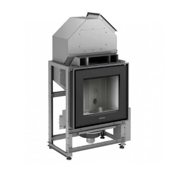
Page 16: Dimensional Diagram Firebox Mp 973
DT1020394-00 2.4 dIMENSIONAL dIAGRAM FIREbOx MP 973 Fig. 26 148,7÷151,5 61,5 60,5 35,5÷38,5 35÷38 29,5÷32,5 20,5÷23,5 Outlet ø 8 52,5 70,5 Dimensions in cm DT2011767-00 2.5 ACCESSORIES ANd EqUIPMENT Description Room sensor NTC 10K Provided Cable L=200 Schuko IEC Provided... -
Page 17: Fuel
Pellets should be stored in a sheltered, dry place. Gruppo Piazzetta S.p.A has tested and programmed its stoves and can ensure best performance and trouble-free operation using pellets with To use good quality pellets with dimensions and heat-producing... -
Page 18: Installation
DT2011822-00 Pursuant to current regulations on the safety of electrical equipment, you must contact a Piazzetta After-Sales Service Centre or a qualified electrician for all and any work connected with installation, maintenance or servicing that involves access inside the cladding/surround or the smoke chamber. -
Page 19: Side Flue Outlet
DT2011823-00 5.2 SIdE FLUE OUTLET Rotating the position of the flue outlet Fig. 28 If it is necessary to move the position of the outlet to the left-hand side, SCREW M6x30 remove the fan as follows: - loosen the screw that secures the smoke sensor to its niche; (Fig. 28); FLANGE - support the fan with one hand and remove the three nuts with washers that secure it to the structure;... - Page 20 - Disconnect the capacitor (3) of the flue gas fan from the relative snap- Fig. 32 in support to be found in the rear part of the electronic board support. DT2032625-00 Fig. 33 - Disconnect the power cable connector (4) of the flue gas fan. - Disconnect the wiring from the electronic board support at the point of the relative quick connector (5).
-
Page 21: Hopper Opening
DT2011768-01 5.4 hOPPER OPENING The standard MP 973 stove comes with hopper opening on the right Fig. 37 side. (Fig. 37) The opening may, however, be moved to the left side, proceeding as follows: - remove the screws fastening the top element of the cover;... - Page 22 • The examples show ducting system of the two fans. Each figure represents only one example of the many possible solutions. To achieve some of the proposed solutions it is necessary to use a flexible pipe with a diameter of 75 mm, air outlet vents and Y elements, none of which are supplied.
- Page 23 Solution 4 - Fig. 43: Fig. 43 Extending the previous solution with the appliance installed in the room to be heated and heat directed to the front and rear of the appliance with doubling-up using a second Y element at the rear as shown. For the example shown in Figure 43, you can install an outlet with closure for the shortest section allowing for some of the air to be released, without ever closing completely to prevent...
-
Page 24: Installing The Y-Element (Optional)
DT2010347-01 5.6 INSTALLING ThE y-ELEMENT (OPTIONAL) • The ducting of heat to adjoining rooms is at the user’s discretion Fig. 49 according to requirements. • The Y-element, designed to double hot air delivery, may be fitted onto one or both fans at the time the stove is installed. •... -
Page 25: Electrical Connections And Controls
DT2011810-01 5.7 ELECTRICAL CONNECTIONS ANd CONTROLS Power cable (7) Fig. 52 • The stove/firebox comes with a power cable which must be connected to a 230v/50Hz mains socket. Connection to the socket in the right side of the stove/firebox is shown in fig. 54. •... -
Page 26: Use
If the stove is not receiving signals from the remote try bringing the remote closer to the stove. Below are listed the various functions of the remote control’s keys. GRUPPO PIAZZETTA MENU DT2030325-00 H072047UK0 / DT2001513 – 04... -
Page 27: Lighting For The First Time
NUMBER KEY / DISPLAY DESCRIPTIoN Key ON/OFF Allows you to start up or shut down the stove. Pressing the stand-by key and holding it down (for around 5 seconds) until KEYPAD BLOCKED Key LOCK KEYBOARD appears on the display will disable the keypad. To re-enable the keypad press the stand-by key and hold it down (for around 8 seconds) until KEYPAD UNBLOCKED appears on the display. -
Page 28: Start-Up And Normal Functioning
DT2012308-00 6.4 START-UP ANd NORMAL FUNCTIONING • Before proceeding with lighting the stove remember: Fig. 61 Check that the fireside door is well closed. O F F C O N T R O L • The pellet hopper must be full or contain enough fuel to run the stove for the desired time. - Page 29 C L E A N I N G 1 2 : 0 0 2 6 Gruppo Piazzetta. This operation is necessary in order to eliminate ash 1 2 : 0 0 2 6 B R A Z I E R...
- Page 30 Action Description Display message The unit is equipped with a device which informs of the lack of fuel in the hopper. Where the amount of fuel reaches the minimum level, the unit works at minimum power and the message “SHoRT oN PELLET” appears on the display in addition to the time in minutes until the unit goes flat, S H O R T O N replacing the usual display (set power level, time and temperature).
- Page 31 EXTERNAL THERMoSTAT Description Display message Stove operation can be controlled by an external room thermostat (normally open) connected to the power board. For thermostat connection see the table "INSTALLATIoN oF EXTERNAL RooM THERMoSTAT”. The ENERGY SAVING mode cannot be activated if the external thermostat is set on SToP and vice-versa. Operation of the external thermostat is conditioned by the appliance set temperature.
-
Page 32: Possible Problems And Solutions
EMPTY BRAZIER Description Display message E M P T Y E M P T Y E M P T Y If the stove was - either voluntarily or due to power failure - shut down during the START PHASE I E M P T Y B R A Z I E R or START PHASE II, the brazier must be cleaned of unburnt pellets after the smoke motor has been... - Page 33 Description Display message WHAT To Do N O L I T E M P T Y - Press the ON/OFF key to shut the stove down. B R A Z I E R - The alarm beep stops. - The smoke motor remains active for 8 minutes and the display shows the message WAIT CooLING. 1 2 : 0 0 2 2 1 2 : 0 0 2 2 - This message is followed by EMPTY BRAZIER (see the table “EMPTY BRAZIER”).
- Page 34 SHUT DoWN DURING THE START PHASE Description Display message E M P T Y The stove is in START PHASE I and is shut down by pressing the ON/OFF key. B R A Z I E R The readout “EMPTY BRAZIER” appears. Completely empty the brazier before setting a new start-up.
- Page 35 PoWER SUPPLY FAILURE Description Display message The power supply may fail during stove operation. It is necessary to distinguish between: 1) power failure during START PHASE I or START PHASE II; 2) power failure without chrono settings; 3) power failure with chrono settings. Power failure during START PHASE I or START PHASE II.
-
Page 36: Control Panel
DT2010222-07 6.6 CONTROL PANEL The stove is fitted with a digital control panel to operate stove functions Fig. 62 when the LCD remote control is unavailable. The various functions of the control panel are listed below. DT2030332-00 NUMBER KEY / DISPLAY DESCRIPTIoN Key ON/OFF Allows you to start up or shut down the product manually. -
Page 37: Programming
DT2012072-01 6.8 PROGRAMMING With the remote control it is possible to select the following functions from the main MENU : • SELECT LANGUAGE LANGUAGE ENGLISH Remote control LANGUAGE FRANCAIS LANGUAGE NEDERLAND LANGUAGE PORTUGUES MENU LANGUAGE ESPANOL LANGUAGE ITALIANO LANGUAGE DEUTSCH •... -
Page 38: Setting The Clock
DT2011296-00 6.9 SETTING ThE CLOCk The appliance leaves the factory with the clock set therefore simply check that the clock is giving the correct time or adjust for daylight saving time. The correct time setting is required for the use of all time-dependant functions. Setting the clock implies programming the following values: day of the week, hour, minute, day, month, year. -
Page 39: Loading The Auger
6.10 LOAdING ThE AUGER When the stove is new or the pellets have been completely used up, prior to start-up and ignition, carry out the LoADING AUGER M E N U M E N U M E N U function. This function allows auger loading and favours light up because the pellets will be immediately unloaded into the brazier. - Page 40 This type of thermostat allows for three types of programming (DAY - WEEK - WEEK-END) always saved; the programs can be enabled or disabled by selecting the SET CHRONO menu. We recommend having only one program active in order to avoid program overlap. THE CLoCK MUST BE SYNCHRoNISED BY SETTING CURRENT DAY, HoURS AND MINUTES THE FIRST TIME THE PRoGRAM IS ACTIVATED, similar to buying a new watch and setting the current time.
- Page 41 D A Y D A Y P R O G R A M P R O G R A M D A Y P R O G R A M D A Y P R O G R A M o f f o f f o f f...
- Page 42 W E E K W E E K W E E K W E E K W E E K Function Action Display message Press SELECT MENU and select on to enable the week program or off E N A B L E E N A B L E E N A B L E E N A B L E...
- Page 43 R O O M R O O M Function Action Display message E N A B L E E N A B L E S E T S E T Set desired Press SELECT MENU to set the desired fan speed (for example, you want W E E K W E E K Multifuoco fan speed...
- Page 44 P R O G R A M W E E K - E N D P R O G R A M W E E K - E N D P R O G R A M W E E K - E N D P R O G R A M W E E K - E N D 0 6 : 0 0...
-
Page 45: Fan Mode
DT2040069-04 6.12 FAN MOdE This function allows you to have the two fans operating at the same speed (NORMAL FANS) or at different speeds (SEPARATE FANS). To maximise the potential of the Multifuoco fan functions, read the sections MULTIFUOCO SYSTEM e MULTICOMFORT OPERATION. FAN MoDE Function Action... -
Page 46: Energy Saving
MULTICoMFoRT This function is used to choose the sensor for reading the room temperature, from the stove or the remote control. To maximise the potential of the Multifuoco fan functions, read the sections MULTIFUoCo SYSTEM and MULTICoMFoRT oPERATIoN. Function Action Display message M U L T I M U L T I... - Page 47 ENERGY SAVING E N E R G Y Function Action Display message E N E R G Y S A V I N G E N E R G Y S A V I N G E N E R G Y S A V I N G E N E R G Y S A V I N G...
-
Page 48: Enable Beep (Audio Signal)
DT2040065-03 6.15 ENAbLE bEEP (AUdIO SIGNAL) This function allows you to engage or disengage the beep signal emitted by the stove to indicate that it has received the remote control commands. ENABLE BEEP (audio signal) Function Action Display message E N A B L E E N A B L E Select enable beep Press the MENU key, then using the SELECT MENU key select ENABLE... -
Page 49: Parameter Menu
DT2011866-00 6.17 PARAMETER MENU The User can only interact with the MEMoRY CoUNTERS in the parameter menu as described in the tables below. The other parameters can only be used by an authorised service centre. MEMoRY CoUNTER Function Action M E N U Display message M E N U M E N U... -
Page 50: Modifying The Transmission Unit
DT2010248-04 6.18 MOdIFyING ThE TRANSMISSION UNIT If two pellets stoves of the same model are installed close to each other and the remote control beam activates both simultaneously, it is possible to modify the transmission unit when the stove has been shut down by proceeding in the following way SELECT UNIT Function Action... -
Page 51: Safety Devices
Finally, if SOLUTION 3 and SOLUTION 4 are selected, even more thrust will be required and in this case fan speed “03”or “04”should be selected on the control panel. To select the desired Multifuoco value, see the paragraph “START-UP AND STANDARD oPERATIoN”. DT2010223-01 6.20 SAFETy dEvICES Some parts of the stove (door, handle, ceramic parts) may reach extremely high temperatures during operation. - Page 52 PELLET HoPPER TEMPERATURE Description Display message The automatic rearm thermal probe is positioned on the pellet hopper and serves to safeguard it against excessive thermal excursions. If the temperature of the pellet hopper exceeds the safety threshold, the thermostat isolates the supply voltage to the auger, thus stopping pellet feed to the brazier, followed by engaged appliance shut down.
- Page 53 SToVE RooM TEMPERATURE PRoBE Description Display message The room probe is connected to the rear of the stove and constantly monitors room temperature near the appliance, allowing for its use in utmost safety. The alarm is triggered if the smoke probe connector momentarily and/or accidentally detaches from its seat.
- Page 54 No LIT Description Display message - The message No LIT E9 is shown on the display. N O L I T This means that the smoke probe has not detected the necessary temperature increase during start 1 2 : 0 0 2 2 - The alarm beep sounds.
-
Page 55: Opening The Door
DT2011042-00 6.21 OPENING ThE dOOR During operation the door must remain closed. It is to be Fig. 63 opened only when the stove has been shut down and cooled for the carrying out of maintenance. The appliance is fitted with a concealed handle in the bottom right part of the door. -
Page 56: Maintenance
7.0 MAINTENANCE DT2011825-00 With reference to the safety standards in force overseeing electrical appliances, in the instance of all installation, maintenance or intervention operations, which involve accessing the inside of the cladding or smoke box, you must seek the assistance of a Technical Support Centre or qualified personnel. -
Page 57: Cleaning The Combustion Chamber
DT2010324-03 7.3 CLEANING ThE COMbUSTION ChAMbER Once a week clean the firebox as follows: Fig. 66 - remove the grate and the ash tray; Upper rear baffle - loosen but do not remove the two hexagon-head brass screws M6 Left side located on the sides in the top part of the two lateral baffles;... -
Page 58: Cleaning The Enamelled Metal Parts
The stove is fitted with a 4mm thick glass panel, resistant to thermal shock up to 750°C; the glass can only be broken by heavy impact or misuse. Do not slam the door or hit the window. In case of breakage replace only with a Gruppo Piazzetta spare part. To replace, proceed as follows: - wear protective gloves;... -
Page 59: Cleaning The Fans
Any build-up of dust or ash on the blades can unbalance them resulting in noise during operation. It is necessary to have the fans cleaned annually. Since such an operation involves dismantling certain parts of the stove, have the cleaning carried out only by a Piazzetta Service Centre or other qualified persons. DT2010096-04 7.11 whEN NOT IN USE... -
Page 60: Main Anomalies
8.0 MAIN ANOMALIES (In grey the user operations) DT2012630-00 Some of the anomalies below can be resolved by following the instructions. All operations must be carried out when the appliance is cold and in the absence of electrical power (pull the plug). As pursuant to law, qualified personnel must resolve anomalies or make repairs that require work to be performed on the components inside the covering or combustion chamber. - Page 61 Problem Cause Solution Evacuation system obstructed Clean the smoke evacuation system Faulty electronic board. Replace the electronic board (use only original parts). Threshold temperature probe is faulty Replace the control probe (use only original parts). THRESHoLD TEMPERATURE Check the proper position of the probe in its seat (see wiring Incorrect position of the smoke probe.
-
Page 62: Replacing The Fuses
Fuse carrier drawer DT2030897-00 EURoPEAN REGULATIoNS DT2010382-05 This product “Pellet - Firebox MP 973” with Multicomfort has been designed, tested and manufactured according to the European R&TTE Directives 1999/5/EC. Following these Directives, this product can be installed in the following countries: (BE) - Page 64 Product serial number, to be quoted when requesting service from the After-Sales Service Centre. Via Montello, 22 31011 Casella d’Asolo (TV) - ITALY Tel. +39.04235271 - Fax +39.042355178 www.piazzetta.it e-mail:infopiazzetta@piazzetta.it...
Need help?
Do you have a question about the MP 973 and is the answer not in the manual?
Questions and answers