
Related Manuals for Quatech ES-100M


Summary of Contents for Quatech ES-100M
- Page 1 ES-100M / QS-100M Multi-port Asynchronous Communications Adapter User's Manual QUATECH, INC. TEL: (330) 434-3154 662 Wolf Ledges Parkway FAX: (330) 434-1409 Akron, Ohio 44311 BBS: (330) 434-2481...
- Page 2 ES-100 User's Manual Version 2.00 October 1994 P/N. 940-0019-200...
-
Page 3: Warranty Information
Quatech Inc. warrants the to be free of defects for one (1) year from the date of purchase. Quatech Inc. will repair or replace any adapter that fails to perform under normal operating conditions and in accordance with the procedures outlined in this document during the warranty period. -
Page 4: Table Of Contents
TABLE OF CONTENTS List of Figures I. General Information II. Installation III. Addressing Ports IV. Interrupt Level (IRQ) Interrupt Sharing Interrupt Status Register V. External Connections Channel Output Configuration VI. Serial Port Functional Description Accessing the Serial Port Registers Interrupt Enable Register Interrupt Identification Register FIFO Control Register Line Control Register... -
Page 5: List Of Figures
LIST OF FIGURES Figure 1. Default address and IRQ settings Figure 2. Diagram of QS-100M / ES-100M Figure 3. Port address map Figure 4. Examination of a serial port base address Figure 5. Serial port base I/O address selection switches Figure 6. -
Page 6: General Information
IRQ14, or IRQ15. (Early versions of the QS/ES-100M are limited to IRQ2-7.) All ports on the QS/ES-100M share one interrupt level. A special interrupt status register is provided to allow controlling software to manage the shared interrupt level. The shared interrupt feature minimizes the system resources consumed by the adapter. -
Page 7: Installation
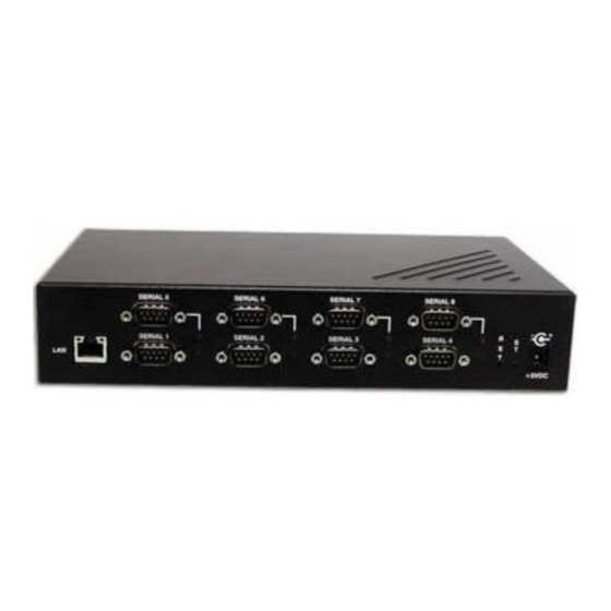
INSTALLATION If the default address and interrupt settings are sufficient, the QS/ES-100M can be quickly installed and put to use. The factory defaults are listed in Figure 1. PORT ADDRESS Serial 1 300 hex Serial 2 308 hex Serial 3... - Page 8 Figure 2 --- Diagram of QS/ES-100M Quatech QS-100M/ES-100M User's Manual...
- Page 9 (This page left blank intentionally.) Quatech QS-100M/ES-100M User's Manual...
-
Page 10: Iii. Addressing Ports
A full sixteen bit address decode is implemented to reduce the chance of address conflicts with other adapters in the system. The base address of the QS/ES-100M can be set anywhere in the range of 0000 hex to FFFF hex. Each serial port on the QS/ES-100M uses 8 consecutive I/O locations. -
Page 11: Figure 4. Examination Of A Serial Port Base Address
A5 on the QS-100M and is not used on the ES-100M. This reflects the different I/O space requirements of the two products. The remaining address lines, A4 - A0 for the QS-100M, or A5 - A0 for the ES-100M, are used by the UART to select the register being accessed. -
Page 12: Figure 5. Serial Port Base I/O Address Selection Switches
Position 6 of SW2 is used to enable or Factory default setting --- 0300 hex disable the interrupt status register. (no digits) Another Example --- 5AC0 hex (no digits) Figure 5 --- Serial port base I/O address selection switches Quatech QS-100M/ES-100M User's Manual... -
Page 13: Interrupt Level (Irq)
IV. INTERRUPT LEVEL (IRQ) The QS/ES-100M allows the use of any interrupt level in the range IRQ2 to IRQ7, IRQ10 to IRQ12, IRQ14, or IRQ15, selected using jumper pack J10. (Early versions of the QS/ES-100M are limited to IRQ2-7.) Figure 6, the factory default setting of IRQ3 is shown. To select a different IRQ, move the jumper to the appropriate position on J10. -
Page 14: Figure 7. Enabling The Interrupt Status Register
Interrupt Status Register Scratchpad Register (factory default) Slide position 6 of SW2 toward the top of the QS/ES-100M to enable the interrupt status register, or toward the bottom of the QS/ES-100M to disable it. Figure 7 --- Enabling the Interrupt Status Register... -
Page 15: External Connections
Figure 10. (20) (20) (20) (20) (20) (22) (22) (22) (22) (22) (22) Typical DTE-to-DCE cable Typical DTE-to-DTE null modem cable Figure 10 --- Cabling requirements for RS-232-C devices (cables using 25-pin connectors shown) Quatech QS-100M/ES-100M User's Manual... -
Page 16: Channel Output Configuration
Channel Output Configuration The QS/ES-100M connects to peripheral equipment through RJ-11 connectors, or using the optional adapter cables, male D-25 connectors. When the RJ-11 connector is converted to a D-25 connector, the conversion cable must be assembled with respect to either a DTE or DCE configuration. -
Page 17: Figure 13. Auxiliary Signal Configuration Jumpers
AUXIN may be selected to be either CTS or DSR. AUXOUT may be selected to be either RTS or DTR. The decision of which signals to use is made separately for each channel. Figure 13 --- Auxiliary signal configuration jumpers. Quatech QS-100M/ES-100M User's Manual... -
Page 18: Figure 14. Output Connector Configuration
RJ-11 connector may be configured to input DCD in place of the chassis ground connection. The decision to connect pin 3 to chassis ground or DCD may be made on a per channel basis using jumpers J11 through J18. Figure 14 --- Output connector configuration. Quatech QS-100M/ES-100M User's Manual... -
Page 19: Serial Port Functional Description
Independent and prioritized interrupts. Transmit clock output / receive clock input. The QS/ES-100M's serial ports are controlled by 16450 or 16550 UARTs. The serial ports will generate interrupts in accordance with the bits set in the interrupt enable register of the UARTs. In order to maintain... -
Page 20: Accessing The Serial Port Registers
I/O address. This I/O address is determined by adding an offset to the base address set for the particular serial port. The base address is set using DIP switches on the QS/ES-100M (see section III). Notice that two locations access different registers depending on whether an I/O read or I/O write is attempted. -
Page 21: Interrupt Enable Register
UART, but are not reported in this register until the access completes. For the 16550 only, this register can be used to indicate whether the FIFO mode is engaged by examining bits 6 and 7. Quatech QS-100M/ES-100M User's Manual... -
Page 22: Figure 17. Interrupt Identification Register Bit Definitions
MODEM Status: Indicates clear to send, data set ready, ring indicator, or data carrier detect have changed state. The interrupt is cleared by reading the MODEM status register. Figure 18 --- Interrupt Identification Register bit decoding Quatech QS-100M/ES-100M User's Manual... -
Page 23: Fifo Control Register
I/O address [base+2]. It is used to enable the FIFO mode, clear the FIFOs, set the threshold level for the receive FIFO to generate interrupts, and to set the mode under which the device uses DMA. Note that DMA mode is NOT supported by the QS/ES-100M. DESCRIPTION RXT1 ---... -
Page 24: Line Control Register
6 bits 7 bits 8 bits 5 bits 6 bits 7 bits 8 bits Word length select: WLS1 --- Determines the number of bits per WLS0 --- transmitted word. Figure 20 --- Line Control Register bit definitions Quatech QS-100M/ES-100M User's Manual... -
Page 25: Modem Control Register
Send). It is also possible to place the UART in a loopback mode for testing. Finally, the user-defined outputs OUT1 and OUT2 are controlled from this register. The QS/ES-100M handles the OUT1 and OUT2 signals in the manner appropriate for maintaining compatibility with standard PC serial ports: The OUT1 output is not connected. -
Page 26: Line Status Register
The bits are reset by reading the line status register. In 16550 FIFO mode, these bits are associated with a specific character in the FIFO and the exception is revealed only when that character reaches the top of the FIFO. Quatech QS-100M/ES-100M User's Manual... -
Page 27: Modem Status Register
This register is located at I/O address [base+7]. It is not used by the 16450 or 16550. It may be used by the programmer for temporary data storage. The Scratchpad Register is eight bits wide and can be read or written. Quatech QS-100M/ES-100M User's Manual... -
Page 28: Fifo Interrupt Mode Operation
FIFO since the last time the transmitter holding register was empty. 3. The first transmitter interrupt after enabling the FIFO mode will be immediate if that interrupt is enabled. Quatech QS-100M/ES-100M User's Manual... -
Page 29: Fifo Polled Mode Operation
4. The Transmitter Empty bit indicates that the transmitter shift register is empty as well as the transmit FIFO being empty. 5. Trigger levels and FIFO timeouts do not apply. Both FIFOs are fully capable of holding multiple characters at any time. Quatech QS-100M/ES-100M User's Manual... -
Page 30: Baud Rate Selection
Standard personal computer serial interfaces use an input clock of 1.8432 MHz. To increase versatility, the QS/ES-100M uses an 18.432 MHz crystal and a frequency divider circuit to produce the standard clock frequency. Jumper block J1 is used to set the frequency input to the UART. It may be connected to divide the clock input by 1, 2, 5, or 10. -
Page 31: Figure 25. Divisor Latch Settings For Common Baud Rates
VALUE ACTUAL VALUES (%) 2304 1536 1047 0.026 1200 1800 2000 0.69 2400 3600 4800 7200 9600 19200 38400 56000 2.86 Figure 25 --- Divisor Latch settings for common baud rates using 1.8432 MHz input clock Quatech QS-100M/ES-100M User's Manual... -
Page 32: Serial Port Functional Description
16-bit bus IBM PC-AT compatible Dimensions: 13.4" x 4.2" Serial ports Number of ports: QS-100M --- four ports ES-100M --- eight ports Controllers: 16450 (16550 optional) Interface: RJ-11 connector Male D-25 connector (using optional adapter cables) Transmit drivers: MC1488 or compatible... -
Page 33: Viii. Troubleshooting
2. Is the base address correctly set? Check for address conflicts with other devices in the system. Remember that the QS-100M requires 32 bytes of I/O space and the ES-100M requires 64 bytes of I/O space. Set a different address if necessary.
Need help?
Do you have a question about the ES-100M and is the answer not in the manual?
Questions and answers