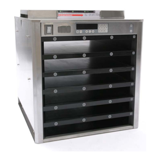
Frymaster UHC-HD Service & Parts Manual
For 6, 3-row models
Hide thumbs
Also See for UHC-HD:
- Service & parts manual (24 pages) ,
- Installation & operating manual (24 pages)
Advertisement
Table of Contents
- 1 Functional Description
- 2 Updating Software/Capturing Configurations
- 3 Service Procedures
- 4 Capture Cabinet Menus/Configurations
- 5 Update: Language File
- 6 Update: Boards
- 7 Readdressing the Cabinet
- 8 Accessing the Electronic Components
- 9 Circuit Board LED Diagnostics
- 10 Tests
- 11 Removing/Replacing Bezels
- 12 Cabinet Troubleshooting
- 13 Cabinet Parts
- 14 Parts Lists, Exploded Views
- Download this manual
Advertisement
Table of Contents

Related Manuals for Frymaster UHC-HD


Summary of Contents for Frymaster UHC-HD
- Page 1 Frymaster, a member of the Commercial Food Equipment Service Association, recommends using CFESA Certified Technicians. Price: $6.00 *8196606* 24-Hour Service Hotline 819-6606 1-800-551-8633 OCT 10...
- Page 2 FROM FRYMASTER DEAN, OR ANY OF ITS AUTHORIZED SERVICE CENTERS, AND/OR THE PART BEING USED IS MODIFIED FROM ITS ORIGINAL CONFIGURATION, THIS WARRANTY WILL BE VOID. FURTHER, FRYMASTER DEAN AND ITS AFFILIATES WILL NOT BE LIABLE FOR ANY CLAIMS, DAMAGES OR EXPENSES INCURRED BY THE CUSTOMER WHICH ARISE DIRECTLY OR INDIRECTLY, IN WHOLE OR IN PART, DUE TO THE INSTALLATION OF ANY MODIFIED PART AND/OR PART RECEIVED FROM AN UNAUTHORIZED SERVICE CENTER.
- Page 3 Table of Contents Theory of Operation Service/Software Procedures Troubleshooting Illustrated Parts List Wiring Diagrams...
-
Page 4: Functional Description
1 Functional Description Power switch 1.2 Theory of Operation The cabinet operates on 208-250VAC 50 or 60 cycle single-phase power. The main switch activates a relay, which supplies line voltage to two distribution boards, three cooling fans and a power supply. - Page 5 Cabinet Service Procedures 1.3 Start Up Indicators and Test Points Upon startup, the cabinet beeps. LED’s on the distribution boards flash. The displays show the version number of the cabinet’s firmware and then the row’s status. Distribution boards shown with ribbon cables removed.
-
Page 6: Updating Software/Capturing Configurations
Cabinet Service Procedures 2 Service Procedures DANGER: Failure to disconnect power from the unit before servicing could result in serious injury or death. The cabinet power switch DOES NOT disconnect all incoming power to the cabinet. Fig. 1: The sides are held in place by screws near the base of the unit on each side. ... -
Page 7: Capture Cabinet Menus/Configurations
Cabinet Service Procedures Update: Boards 1. Turn power off. 2. Insert flash drive in USB port located on cabinet bezel. 3. Turn power on. 4. Cabinet displays version numbers followed by current menu setting. 5. Press programming key. 6. Screen scrolls Enter Access Sequence. 7. - Page 8 Cabinet Service Procedures USB. 6. Press OK. 7. The master control displays Please Wait… as files are transferred to the flash drive, changing to the number of files copied when the process is complete. 8. Press OK. 9. Remove flash drive. 10.
- Page 9 Cabinet Service Procedures 2.2 Placing the cabinet in Service Mode The cabinet can be put in service mode, a diagnostic settings which allows the heater plates to be controlled individually, brightness settings on the displays adjusted and re-addressing for unique arrangements of bezels.
-
Page 10: Readdressing The Cabinet
Cabinet Service Procedures Readdressing the Cabinet Addressing, or assigning a position-specific component such as a display or distribution board, is done automatically by the cabinet on startup. Communication errors can occur on start-up after a board installation however. If so, follow the instructions below to readdress the cabinet. This process can also be used during troubleshooting when displays are connected out of synch with their associated bezel on the same row level. -
Page 11: Accessing The Electronic Components
2.3 Accessing the Electronic Components 1. The component shelf is accessed by removing two screws on each side of the unit (Fig. 1). 2. Lift and remove the sides, which exposes screws that hold the top in place (Fig. 2). 3. -
Page 12: Tests
Cabinet Service Procedures • ERR LED toggles when a communication error is detected; it’s not unusual to see a flash, but regular flashing means communications problems. • LED5 and LED6 used for programming/debugging; have no diagnostic function. • LED7 When lit, the master control is executing a time or temp query operation on the front side. - Page 13 Cabinet Service Procedures suspect heater. Note: Line voltage is only seen when the row is calling for heat. 2. Check for line voltage between the power input terminal and the terminal block. 3. Check for +5VDC at the power-in terminal and the terminal block for the power supply.
-
Page 14: Removing/Replacing Bezels
Cabinet Service Procedures 3. HHHH means RTD indicates the temperature is above 255°F (124°C), but below "Open" circuit resistance, which causes SENS ALARM. 4. UHC VERSION _ _ _ (version number will vary) appears for five seconds when the unit is turned on. 5. - Page 15 Cabinet Service Procedures 2.6. 1 Removing/Replacing a Distribution Board or Communication Board 1. Remove power. 2. Remove and mark the wires on the faulty component. 3. Remove the board by lifting it from its standoffs. 4. Position the new board and attach wires.
- Page 16 Cabinet Service Procedures 9. Slide the row assembly completely into the cabinet and return the spacers between the heater plates. Ensure the row is evenly positioned in the cabinet. There must be sufficient space to allow the bezel tabs to fit between the outside row plate and the cabinet interior wall.
-
Page 17: Cabinet Troubleshooting
Cabinet Troubleshooting The master control display and the row displays show error messages when there is a problem. The messages are shown in the matrix below along with possible causes and diagnostic tests. Error Message Call service row display error Row number also displayed * ... - Page 18 Cabinet Troubleshooting Failure modes not accompanied by a master control display are shown below with possible causes and tests. Symptom Possible Causes • No power to cord. • Unit fails to power Blown 20 amp fuse. • up; fans don’t run. Circuit breaker open.
-
Page 19: Cabinet Parts
Parts Lists, Exploded Views Part Number Item 108-1897 Top Cap 823-7636 Rear Fascia 807-4882 Circuit Breaker, 16 amp 807-5111 Time/Temperature switch 807-4911 Power switch 823-7513 Front fascia 807-5112 Master control overlay with ribbon cable 807-5156 Master display board (circuit board in master display assembly) Cabinet Parts Description... - Page 20 Part Number Item 807-5111 Time/Temperature switch 826-2781 Bezel, with boards, front with short ribbon cable 826-2782 Bezel with boards, rear, with long ribbon cable 108-1190 Base 807-4857 Heater plate/RTD 807-4860 Distribution board 108-1633 Side, left, vented 108-1632 Side right, not vented Component Shelf Part Number Item...
- Page 21 Part Number Item 807-4868 Power Supply 807-3490 Power relay 406-0011 UHC-HD Single Filter Board Ribbon Cables 807-4916 Time/Temp 18” used for front fascia 807-4917 Time/Temp 32” used for rear fascia 807-4875 Master distribution 807-4922 Power to upper distribution board 807-4923...
- Page 22 Cabinet Wiring Diagrams Wiring Diagram, Delta Power, L1-L2...
- Page 23 Cabinet Wiring Diagrams UHC-HD, WYE Power, L1-N...
- Page 24 Frymaster, L.L.C., 8700 Line Avenue, Shreveport, Louisiana 71106 TEL 1-318-865-1711 FAX (Parts) 1-318-219-7140 FAX (Tech Support) 1-318-219-7135 Price: $6.00 SERVICE HOTLINE 819-6606 PRINTED IN THE UNITED STATES 1-800-551-8633 OCT 2010...
Need help?
Do you have a question about the UHC-HD and is the answer not in the manual?
Questions and answers