Table of Contents
Advertisement
Quick Links
Advertisement
Table of Contents

Related Manuals for NetComm NP2724M


Summary of Contents for NetComm NP2724M
-
Page 1: User Guide
VLAN Managed Switch User Guide NP2724M User Guide www.netcomm.com.au... -
Page 2: Table Of Contents
2.2. Switch Front and Rear Panel ............3 2.2.1. NP2724M ................3 2.3. LED Function ...................4 2.4. Reset Button ..................4 2.5. Installing the NP2724M..............4 2.6. Rack- Mount Placement..............6 2.7. Preparing for configuration...............8 2.7.1. Connecting a PC or Terminal to the RS-232 Port....9 2.7.2. -
Page 3: Introduction
1. Introduction Thank you for choosing the NetComm NP2724M 24 port 10/100 + 2 Gigabit VLAN Managed Switch. These switches are a cost-effective switching solution idea for small business and the network edge. It provides Quality of Service (QoS) features, such as 802.1p, DSCP and Rate Control, to ensure the traffic is prioritized properly to deliver real-time applications like voice and video and to also maintain a good control in network bandwidth usage. -
Page 4: Installation
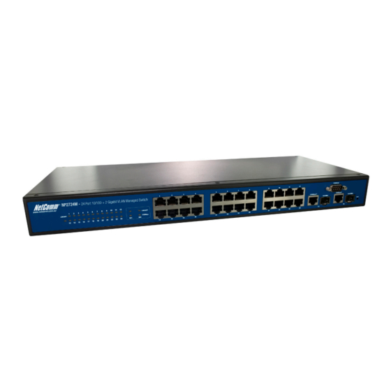
2.2.1. NP2724M The front panel of the NP2724M 24 port 10/100 + 2 Gigabit VLAN Managed switch has 24 10/100 Mbps copper ports at the left, 2 10/100/1000 Mbps copper ports and 2 Gigabit SFP slots at the right. The product name is indicated at the top on the left. -
Page 5: Led Function
Please note, you will lose unsaved change when doing this. 2.5. Installing the NP2724M This section describes how to install and make connection to your NP2724M Managed Switch. The following diagrams shows the a typical network configuration, Figure 2.5.1 shows the network configuration for NP2724M... - Page 6 Do not stack free-standing switch more than four units high. One other way to deploy multiple NP2724M’s is by using a star network topology and connect. Desktop or Shelf Mounting To install the switch on a desktop or shelf, simply complete the following steps: Step 1 Place the switch on a desktop or shelf near an AC power source.
-
Page 7: Rack- Mount Placement
Appropriate consideration of equipment nameplate ratings should be used when addressing this concern. E) Reliable Earthing - Reliable earthing of rack-mounted equipment should be maintained. Particular attention should be given to supply connections NP2724M User Manual... - Page 8 Then attach the other bracket to the other side. (Figure 2.6.1) Figure 2.6.1 Make sure the brackets are properly attached to the Switch. Use the appropriate screws (not included) to securely attach the brackets to your rack. (Figure 2.6.2) Figure 2.6.2 NP2724M User Manual...
-
Page 9: Preparing For Configuration
Users can use this interface to perform device configuration. There are four methods to manage your switch: Local Console Management You can manage the NP2724M switch locally by connecting the switch to a PC or workstation with terminal emulation software using the serial port. Remote Console Management You can manage the switch by having a remote host establish a Telnet connection to the switch via an Ethernet or modem link. -
Page 10: Connecting A Pc Or Terminal To The Rs-232 Port
Web-Browser You can manage the switch through a web connection by connecting to the switch’s IP address using your web browser. NP2724M default IP address: http://192.168.1.254 Default User Name: admin Default Password: (blank) This User Guide provides instructions on how to configure the switch using the console interface. -
Page 11: Logging On The Switch
Logging on the switch To log on to the Switch: 1. In your web browser, specify the IP address of NP2724M. Default IP address is 192.168.1.254. 2. Enter the factory default user name: “admin“ and no password to login to the web management interface of the switch. -
Page 12: User Mode Commands
The command prompt at this level is: Command Prompt: Switch(Interface <port#>)# 2.9.2. User Mode commands help This command displays help information Format help Mode User Mode This command displays help information Format help Mode User Mode logout NP2724M User Manual... -
Page 13: Privileged Mode Commands
This command is used to clear ARL table entries Format clear arl Mode Privileged Mode 2) clear arl dynamic This command is used to Clear dynamic arl table entries Format clear arl dynamic Mode Privileged Mode 3) clear arl static NP2724M User Manual... - Page 14 This command is used to upload file from switch to host, or download file to switch from host 1) copy nvram_config This command is used to backup switch configuration Format copy nvram_config tftp <A.B.C.D> file <filename> Mode Privileged Mode e.g. Switch#copy nvram_config tftp 192.168.1.100 file switch_configuration NP2724M User Manual...
- Page 15 This command is used to show configured data 1) show qos This command display class of service information 1.1) show qos cos This command display the cos mapping Format show qos cos Mode Privileged Mode 1.2) show qos queue-settings NP2724M User Manual...
- Page 16 This command display dynamic router ports information Format show igmp snooping dynamic_router_port Mode Privileged Mode 3.2) show IGMP snooping groups This command is used to display igmp groups information Format show IGMP snooping groups Mode Privileged Mode NP2724M User Manual...
- Page 17 Format show logging memory-log Mode Privileged Mode 7.2) show logging flash-log This command display flash logs Format show logging flash-log Mode Privileged Mode 8) show monitor This command is used to display port mirroring settings Format show monitor NP2724M User Manual...
- Page 18 This command is used to display all snmp config 14.1) show snmp groups This command display all snmp groups Format show snmp groups Mode Privileged Mode 14.2) show snmp users This command display all snmp users Format show snmp users Mode Privileged Mode NP2724M User Manual...
- Page 19 This command is used to display system information including system up time Format show sysinfo Mode Privileged Mode 19) show switch This command is used to display switch information 19.1) show switch admin-time This command display the age time of web and console NP2724M User Manual...
- Page 20 22.5) show rmon alarm 22.5.1) show rmon alarm index This command displays rmon Alarm. Format show rmon alarm index <1..65535> Mode Privileged Mode 22.5.2) show rmon alarm Format show rmon alarm<CR> Mode Privileged Mode 22.5.3) show rmon event log NP2724M User Manual...
-
Page 21: Global Config Mode Commands
This command is used to configure vlan 1) vlan add This command is used to create a new vlan 1.1) vlan add number This command enter a vlan ID Format vlan add number <vlan-ID> Mode Global Config NP2724M User Manual... - Page 22 This command is used to configure protected ports Format vlan port ports protected {enable|disable} Mode Global Config 4.2.3) vlan port ports pvid This command is used to configure port vid Format vlan port ports pvid < vlan-ID> NP2724M User Manual...
- Page 23 Format link aggregation delport lag <LAG-ID> Mode Global Config lldp 1) lldp enable This command is used to enable lldp functions Format lldp enable Mode Global Config 2) lldp disable This command is used to disable lldp functions Format lldp disable NP2724M User Manual...
- Page 24 Format log log-server name <WORD> delete Mode Global Config 2) log logging-target This command is used to configure log notification level 2.1) log logging-target memory This command is used to specify memory log notify-level Format log logging-target memory {enable|disable} Mode Global Config NP2724M User Manual...
- Page 25 DUT. Format mgmt-accesslist enable Mode Global Config 3) mgmt-accesslist disable This command disables management access list. Format mgmt-accesslist disable Mode Global Config monitor 1) monitor enable This command enables port mirroring. Format monitor enable Mode Global Config NP2724M User Manual...
- Page 26 Switch(config)# dot1x port-control disable port 1-4 network 1) network mgmt-vlan This command changes management vlan. Format network mgmt-vlan <vlan-ID> Mode Global Config 2) network parms This command configures static IP address of the switch. Format network parms <IP addr> <subnet mask> <gateway> NP2724M User Manual...
- Page 27 This command configures web/console admin time out interval. ‘0’ means disable. Format network admin-timeout <0-65535> Mode Global Config port-all 1) port-all admin-mode This command configures ports admin mode. Format port-all admin-mode {enable | disable} Mode Global Config 2) port-all auto-negotiate NP2724M User Manual...
- Page 28 Mode Global Config 8.3) port-all storm-control broadcast-multicast This command configures storm control for broadcast and multicast. Format port-all Storm-Control broadcast-multicast <value> Mode Global Config 8.4) port-all storm-control broadcast-unknown This command configures storm control for broadcast and unknown NP2724M User Manual...
- Page 29 5.2) qos scheduling wrr This command sets to Weight Round-Robin. Format qos scheduling wrr Mode Global Config 6) qos ip-precedence This command configures IP precedence queue mapping. Format qos ip-precedence <0-7> queue <1-4> Mode Global Config 7) qos wrr NP2724M User Manual...
- Page 30 This command specifies igmp router port. Format set igmp router-port ports <port list> Mode Global Config e.g. Switch(config)# set igmp router-port ports 1-10 2) set igmp-querier This command configures igmp querier. Format set igmp-querier {enable | disable} NP2724M User Manual...
- Page 31 This command creates a community. Format snmp community add <community name> group <group name> mgmt-ip <ip-addr> Mode Global Config 4.2) snmp community delete This command deletes a community. Format snmp community delete <community name>. Mode Global Config NP2724M User Manual...
- Page 32 Mode Global Config 2.2) sntp localtime localtime_date This command sets local time. Format sntp localtime localtime_date <year> <month> <date> <hour> <minute> <second> Mode Global Config 3) sntp server 3.1) sntp server enable This command enables sntp server. NP2724M User Manual...
- Page 33 3) spanning-tree forward-time This configures the bridge forward delay parameter. Format spanning-tree forward-time <4-30> Mode Global Config 4) spanning-tree max-age This command configures the bridge max age parameter. Format spanning-tree max-age <6-40> Mode Global Config 5) spanning-tree max-hops NP2724M User Manual...
- Page 34 This command removes the last MST instance. Format spanning-tree mst instance delete Mode Global Config 8.2) spanning-tree mst vlan This command adds or deletes vlan frome a MSTP instance. 8.2.1) spanning-tree mst vlan <MST ID> <vlan list> add NP2724M User Manual...
- Page 35 <0..65535> feindex<0..65535> owner< WORD> Mode Global Config e.g. Switch(Config)# RMON alarm index 1 interval 10 interface counter 1 sample delta start all rthreshold 100 fthreshold 10 reindex 1 feindex 0 owner test 3) rmon del NP2724M User Manual...
- Page 36 Format access-list name <WORD> clear l4port DST port Mode Global Config 3.4) access-list name <WORD> clear packet-type This command clears packet type filter. Format access-list name <WORD> clear packet-type Mode Global Config 3.5) access-list name <WORD> clear mac SA NP2724M User Manual...
- Page 37 Format Access-list name <WORD> set L4 port SRE-port from <1- 65535> to <1-65535> Mode Global Config 6.3.2) access-list name <WORD> set l4port DST-port This command specifies the destination TCP/UDP port range. Format access-list name <WORD> set l4port DST-port from <1- 65535> to <1-65535> Mode Global Config NP2724M User Manual...
-
Page 38: Interface Config Mode Commands
3) tacplus del This command is used to delete a TACACS+ server. Format tacplus del server <IP_addr> Mode Global Config 2.9.5. Interface Config mode commands exit Exit current shell Format exit Mode Interface Config dot1x Set 802.1x port control. NP2724M User Manual... - Page 39 Mode Interface Config e.g. Switch(Interface 1)#lldp med-notification enable 4) Configures which TLVs are enabled for transmission. 4.1) basic set Format lldp tlvs-tx {enable | disable} option basic {port-desc | sys-name | sys-desc | sys-capa | sys-capa } NP2724M User Manual...
- Page 40 Format port-security lock-mode {none | static} Mode Interface Config 3) port-security lock-mode dynamic This command enable limited dynamic lock mode,and specify maximin learning entries for limited dynamic lock mode.the max-entries value :0~24 Format port-security lock-mode dynamic max-entries 24 NP2724M User Manual...
- Page 41 This command storm control limited value :0,64,256,1024,10240,65536.102400,1024000,which the unit is Kbps and 0 means no limit. Format storm-control all-cast <rate> Mode Interface Config rmon-counter This command specifies rmon counter capability on a port Format rmon-counter {enable | disable} NP2724M User Manual...
- Page 42 7) spanning-tree priority this command configure RSTP port priority:0~240 format spanning-tree priority <0..240> mode Interface Config vlan 1) vlan participation This command join or leave a port to a vlan. 1.1) vlan participation exclude This command leave a vlan. NP2724M User Manual...
- Page 43 This command configures detection type on a port. set to 0,1,2,3,4 or 5 0 No Detection 1 Legacy Capacitive Detection only 2 IEEE 802.3af 4-Point Detection only (Default) 3 IEEE 802.3af 4-Point followed by Legacy 4 IEEE 802.3af 2-Point only 5 IEEE 802.3af 2-Point followed by Legacy NP2724M User Manual...
- Page 44 Interface Config 4)high-power This command configures power Energy Mode on a port Start High Power (Support 30W power device) End High Power Mode (Support 15.4W power device) Format poe high-power status {enable | disable} Mode interface Config NP2724M User Manual...
-
Page 45: Specifications
There are two types of cables: Straight-through Cables and Crossover Cables. Category 5 UTP/STP cable has eight wires inside the sheath. The wires form four pairs. Straight-through Cables has same pin-outs at both ends while NP2724M User Manual... - Page 46 Crossover Cables has a different pin arrangement at each end. Figure 4-1 shows the diagram of Straight-through Cables. Figure 4-2 shows the diagram of Crossover Cables. NP2724M User Manual...
-
Page 47: Technical Specifications
3.2. Technical Specifications 3.2.1. Software Specification NP2724M 24 Port 10/100 + 2 Gigabit VLAN Managed Switch □Four groups (history, statistics, alarms, and events) of embedded remote monitoring (RMON) agents for network monitoring and traffic analysis □Provides SNMP protocol(v1/v2c/v3) to monitor and control the switch by using SNMP management applications such as HP Open View □... -
Page 48: Hardware Specification
3.2.2. Hardware Specification NP2724M 24 Port 10/100 + 2 Gigabit VLAN Managed Switch □ Supports 24 ports 100Base-TX and 2 1000BaseT with 2 shared Mini-GBIC. □ IEEE 802.3ab Auto MDI/MDI-X on all 10/100/1000 twisted-pair ports □ Automatic polarity detection and correction on all RJ-45 ports for automatic adjustment of wiring errors □... -
Page 49: Standard Conformance
~ 104 ) Operating Temp. Storage Temp. ~ 70 (-40 ~ 158 ) Operating Humidity 20% to 85%,relative humidity, non-condensing Storage Humidity 20% to 90%,relative humidity, non-condensing 3.2.4. Standard Conformance EMC Certification FCC Class A, CE, CTick NP2724M User Manual... -
Page 50: Legal And Regulatory Information
(3) The power supply that is provided with this unit is only intended for use with this product. Do not use this power supply with any other product or do not use any other power supply that is not approved for use with this product by NetComm. - Page 51 1. You, or someone else, use the product, or attempts to use it, other than as specified by NetComm; 2. The fault or defect in your product is the result of a voltage surge subjected to the product either by the way of power supply or communication line, whether caused by thunderstorm activity or any other cause(s);...
- Page 52 Note: NetComm Technical Support for this product only covers the basic installation and features outlined in the Quick Start Guide. For further information regarding the advanced features of this product, please refer to the configuring sections in the User Guide or contact a Network Specialist.
Need help?
Do you have a question about the NP2724M and is the answer not in the manual?
Questions and answers