Table of Contents
Advertisement
Advertisement
Table of Contents
Troubleshooting

Related Manuals for SATO CLLM Basic 412e


Summary of Contents for SATO CLLM Basic 412e
- Page 1 LM Basic (408e/412e) ’ OPERATOR S MANUAL...
- Page 2 All rights reserved. No part of this document may be reproduced or issued to third parties in any form whatsoever without the express permission of SATO. The materials in this document are provided for general information and are subject to change without notice.
-
Page 3: Table Of Contents
TABLE OF CONTENTS 1. OVERVIEW 1.1 General Specifications ..................1-2 2. INSTALLATION Safety Precautions..................... 2-2 2.1 Unpacking......................2-4 2.1.1 Included Accessories ..................2-5 2.1.2 Parts Identification.................... 2-6 2.2 Loading the Carbon Ribbon................2-8 2.3 Loading Labels..................... 2-9 2.3.1 Loading Roll Paper ..................2-10 2.3.2 Loading Fanfold Paper .................. - Page 4 3.6.7 Euro Code ....................... 3-13 3.6.8 Select Language ....................3-13 3.6.9 Command or LCD Priority ................3-13 3.6.10 Ignore CAN/DLE .................... 3-13 3.6.11 Ribbon Near End On/Off ................3-14 3.6.12 IEEE1284 ACK Signal ................... 3-14 3.6.13 Backfeed Speed .................... 3-14 3.7 COUNTERS Mode ....................
-
Page 5: Table Of Contents (Con'td)
TABLE OF CONTENTS (CON’TD) 4. CLEANING AND MAINTENANCE 4.1 Introduction ......................4-1 4.2 Cleaning The Print Head, Platen and Rollers ............ 4-1 4.3 How To Clean The Printer (With A Cleaning Set)..........4-2 4.4 How To Clean The Printer (Cleaning Sheet) ............4-3 4.5 Adjusting Print Quality .................. - Page 6 TABLE OF CONTENTS (CON’TD) 7. OPTIONAL ACCESSORIES 7.1 Introduction ......................7-1 7.2 Available Interface Boards .................. 7-1 7.3 Optional Accessories: Interface boards ............7-2 7.4 Optional Accessories: Others ................7-4...
-
Page 7: Overview
Section 1: Introduction OVERVIEW Thank you for your investment in this SATO printer product. This Operator’s Manual contains basic information about the installation, setup, configuration, operation and maintenance of the printer. A total of seven topics are covered herein, and they are organized as follows:... -
Page 8: General Specifications
Section 1: Introduction 1.1 GENERAL SPECIFICATIONS The SATO LM 408e and 412e are dual-use (Thermal Transfer and Direct Thermal) high performance labeling solutions designed for logistics and manufacturing sectors. Based mechanically on the field-proven CL ‘enhance’ series, the LM408e and LM412e promise reliable operation and consistent performance at a reasonable cost. - Page 9 Transmitted from host (computer) Paper Thickness 0.08 mm to 0.26 mm supported. Note: Be sure to use only printer supplies manufactured or certified by SATO. Paper Size Width: 10mm to 112mm (13 mm to 115 mm including liner) *in continuous mode...
- Page 10 Fan-fold Maximum folding height 100mm External Supply Supported Carbon ribbon Be sure to use the specified carbon ribbons manufactured or specified by SATO Material Polyester film Dimensions Max width 111mm by 450m length Core Inner Diameter 25.6 mm +/- 0.3mm Thickness of base material 4.5 to 5.7µm +/-0.5µm (film), 5.8 to 8.3 µm +/- 0.6µm...
- Page 11 Zero-slash character switching, HEX Dump Print function, Calendar option. DIP Switches One 8-bit DIP switch Programming Language SATO Barcode Printer Language Ver 4.1 Automatic diagnostics Head check function (for detection of failed heating elements in the print head) ”Paper-End” detection “Head Open”...
- Page 12 Section 1: Introduction 1.1 GENERAL SPECIFICATIONS (CONT’D) Specification/ LM408e and LM412e Model Name Barcoding Functions Barcodes One- • UPC-A/E, EAN8/13, JAN8/13 dimensional Supported • NW-7 code • INTERLEAVED 2 of 5 (ITF) • INDUSTRIAL 2 of 5 • MATRIX 2 of 5 •...
- Page 13 Section 1: Introduction Specification/ LM408e and LM412e Model Name Physical Characteristics Dimensions W 430 mm x D 271 mm x H 321 mm (Standard) Weight 13 Kg (for a standard configuration) Power Supply Input voltage: AC100V - 120V or AC200V to 240V ±10% Power Consumption 180 W (peak) Standards Compliance...
- Page 14 Section 1: Introduction This page is intentionally left blank Page 1-8 LM Basic 408e/412e Operator’s Manual...
-
Page 15: Installation
Section 2: Installation INSTALLATION This section assists you in unpacking and installing the printer from the shipping container. You will also be guided through a familiarization tour of the main parts and controls. The following information is provided: • Safety Precautions •... -
Page 16: Safety Precautions
SECTION 2: INSTALLATION SAFETY PRECAUTIONS Please read the following information carefully before installing and using the printer SAFETY PRECAUTIONS THE CAUTION SYMBOL Whenever the triangular Caution logo appears in this manual, pay special attention to the warning(s) cited below it. Failure to abide by the warnings may result in injury or damage to property. PRINTER PLACEMENT TIPS •... - Page 17 Section 2: Installation GENERAL PRECAUTIONS • Head cleaning liquid (if supplied) is flammable. Never • Do not disassemble or perform modifications to heat it or throw it into a fire. Keep it out of children’s the printer, as this renders the product unsafe. reach to avoid accidental consumption.
-
Page 18: Unpacking
SECTION 2: INSTALLATION 2.1 UNPACKING When unpacking the printer, take note of the following: The box should stay right-side up. If the printer was been stored in the Lift the printer out of the box carefully. cold, allow it to reach room temperature before turning it on. -
Page 19: Included Accessories
Section 2: Installation 2.1.1 INCLUDED ACCESSORIES After unpacking the printer, verify that the following materials are in the accessories or packaging: Global Warranty Additional information document leaflets Power cable* Accessory CD-ROM* Operator’s Manual Two-pole adaptor* * Items marked with an asterisk may be different from what you see here, or may be excluded. Important! Please fill out the Global Warranty card and submit it to us in order that we can provide fast and efficient... -
Page 20: Parts Identification
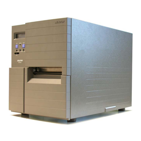
SECTION 2: INSTALLATION 2.1.2 PARTS IDENTIFICATION IDENTIFYING THE MAIN PRINTER PARTS Front and Rear View Main Cover Interface LCD screen Card Slot Operation Panel Fanfold paper slot Power switch Fuse holder Front Cover AC power socket Angled Front View (Main Cover removed) Ribbon Take-Up Shaft Ribbon Feeder Shaft Front Cover... - Page 21 Section 2: Installation 2.1.2 PARTS IDENTIFICATION (CONT’D) IDENTIFYING THE MAIN PRINTER PARTS View of Front Panel 8888888888888888 8888888888888888 LINE STATUS FEED PRINT OFFSET PITCH LCD screen FEED button Icons, prompts and system messages . Feeds the label forward. When it is pressed once, are displayed here.
-
Page 22: Loading The Carbon Ribbon
Lever here. For maximum print quality and printer (purple) durability use genuine SATO carbon ribbons. Caution • When replacing the carbon ribbon, bear in mind that the print head and its surrounding area remain hot. Keep your fingers away from these areas to prevent injury. -
Page 23: Loading Labels
For optimal print performance and durability, please use SATO-certified label and ribbon supplies on this printer. Using supplies not tested and approved for use by SATO can result in unnecessary wear and damage to vital parts of the printer, and may void the warranty. -
Page 24: Loading Roll Paper
SECTION 2: INSTALLATION 2.3 LOADING LABELS (CONT’D) 2.3.1 Loading Roll Paper Main Cover 1. Lift up the main cover. Make sure that the cover is Label Holder pushed upwards until it locks firmly in place so that it will not fall downwards and injure your hands. Label Release the purple Head Lock lever by pushing it Guide Plate... -
Page 25: Loading Fanfold Paper
Section 2: Installation 2.3 LOADING LABELS (CONT’D) 2.3.2 Loading Fanfold Paper Main Cover 1. Lift up the main cover. Make sure that the cover is Head Lock pushed upwards until it locks firmly in place. Remove Lever the fanfold slot cover by removing two screws. Pull the Head Lock Lever upward to release the print head Fanfold assembly. -
Page 26: Adjusting The Paper Sensor
SECTION 2: INSTALLATION 2.3 LOADING LABELS AND TAGS (CONT’D) 2.3.3 Adjusting the Paper Sensor Adjustment of the paper sensors (I-mark and Gap sensors) is usually not necessary, but the procedure is described here when you need to make adjustments. 1. Lift up the main cover. Make sure that the cover is pushed upwards until it locks firmly in place so that it will not fall downwards and injure your hands. -
Page 27: Replacing The Print Head
Section 2: Installation 2.4 REPLACING THE PRINT HEAD Before attempting to replace the print head, it is advisable to contact your local dealer or service center so that they can assist you in case of problems. 1. Make sure the printer has been turned off for at least 30 minutes so that the print head is not hot. Lift up the front cover. - Page 28 SECTION 2: INSTALLATION This page is intentionally left blank Page 2-14 LM Basic 408e/412e Operator’s Manual...
-
Page 29: Configuration And Operation
Note Due to SATO’s continual efforts to improve the printer firmware and hardware, the sequence and availability of LCD menus described here may not be similar to what is available on your version of LM Basic. In this case, visit SATO’s website at http://www.satoworldwide.com for supplementary and updated documentation. -
Page 30: The Operation Panel
Section 3: Configuration and Operation 3.2 THE OPERATION PANEL 8888888888888888 8888888888888888 LINE STATUS FEED PRINT OFFSET PITCH LCD screen FEED button Icons, prompts and system messages Feeds the label forward. When it is pressed once, are displayed here. the equivalent of a sheet of paper or label is ejected. *There are times when the paper is not aligned prop- LINE button erly when power is turned on or when the paper was... -
Page 31: Accessing The Various Printer Modes
Section 3: Configuration and Operation 3.3 ACCESSING THE VARIOUS PRINTER MODES LM Basic 408e/412e Operator’s Manual Page 3-3... - Page 32 Section 3: Configuration and Operation 3.3 ACCESSING THE VARIOUS PRINTER MODES (CONT’D) 3.3.1 How to access special Modes and Menus after turning the power ON Mode/Menu Button(s) to press Comments Normal Press LINE to toggle ONLINE/OFFLINE ONLINE/OFFLINE STATUS Advanced Hold down the LINE button Each time you pressing the LINE button, when turning printer ON you will rotate through Service Mode,...
-
Page 33: Overview Of Lcd Menu Options In Various Modes
Section 3: Configuration and Operation 3.3.2 OVERVIEW OF LCD MENU OPTIONS IN VARIOUS MODES LM Basic 408e/412e Operator’s Manual Page 3-5... - Page 34 Section 3: Configuration and Operation 3.3.2 OVERVIEW OF LCD MENU OPTIONS IN VARIOUS MODES (CONT’D) Page 3-6 LM Basic 408e/412e Operator’s Manual...
- Page 35 Section 3: Configuration and Operation 3.3.2 OVERVIEW OF LCD MENU OPTIONS IN VARIOUS MODES (CONT’D) LM Basic 408e/412e Operator’s Manual Page 3-7...
-
Page 36: Normal Modes
Section 3: Configuration and Operation 3.4 NORMAL MODES 3.4.1 Online ONLINE Pressing the LINE button causes the printer to go ONLINE or QTY:000000 OFFLINE alternately. When the printer is ONLINE, the following activities will be possible: • The printer is ready to receive print data from the computer or other connected devices •... -
Page 37: Print Speed
Section 3: Configuration and Operation 3.4 NORMAL MODES (CONT’D) 3.4.4 Print Speed Pressing LINE repeated cycles through the various available PRINT SPEED speeds. The slowest speed is 2ips, while the highest speed is 6ips. The default speed for the LM Basic 408e is 4ips. Press the FEED button to select a print speed. -
Page 38: Advanced Mode
Section 3: Configuration and Operation 3.5 ADVANCED MODE 3.5.1 Advanced ADVANCED MODE Holding down the LINE button when turning the printer ON causes the printer to go into the Advanced Mode. In the following screens of Advanced Mode, you can control the Darkness Range, Zero Slash symbol, Auto Online option, Print Offset, Calendar settings, Ignore CR/LF function, Character Pitch and Head Check feature. -
Page 39: Set Calendar
Section 3: Configuration and Operation 3.5 ADVANCED MODE (CONT’D) 3.5.6 Set Calendar If a Calendar chip has been installed, this screen allows you to set SET CALENDAR the time and date. The default is NO. Selecting YES calls up a screen for setting the Year, Month, Day, CALENDAR Hour and Minute respectively. -
Page 40: Service Mode
Section 3: Configuration and Operation 3.6 SERVICE MODE 3.6.1 Service SERVICE MODE In this mode, pressing the LINE button brings you to the COUNTERS mode screen. Otherwise, press FEED to proceed to adjust service mode settings. In the following screens of Service Mode, you can control the Slice Level, Auto Line Feed, Feed On Error, Reprint W/Feed, Forward/Backfeed Amount, Forward/Backfeed Distance, Euro Code symbol, Menu Language, Command/LCD Priority. -
Page 41: Forward/Backfeed Amount
Section 3: Configuration and Operation 3.6 SERVICE MODE (CONT’D) 3.6.6 Forward/Backfeed Amount FORWARD/BACKFEED This setting allows customization of the label feed/backfeed DISTANCE DEFAULT distance instead of the default setting. If DISTANCE is selected, the next menu appears, for setting of the FORWARD/BACKFEED amount of label feed/backfeed. -
Page 42: Ribbon Near End On/Off
Section 3: Configuration and Operation 3.6 SERVICE MODE (CONT’D) 3.6.11 Ribbon Near End On/Off RIBBON NEAR END This screen lets you enable or disable the early detection and ENABLE DISABLE warning of the ribbon supply reaching an end. The default value is ENABLE Use the LINE button to select ENABLE or DISABLE, then press the FEED button for the next screen. -
Page 43: Counters Mode
Section 3: Configuration and Operation 3.7 COUNTERS MODE 3.7.1 Counters COUNTERS MODE In this mode, pressing the LINE button brings you to the Motion Mode settings. Otherwise, press FEED to proceed to adjust the behavior of the built-in counters. In the following screens of Counters Mode, you can choose between the Head Counter or Life Counter, see the Head Counter value, clear the Head Counter, and see the Life Counter value. -
Page 44: Move Mode
Section 3: Configuration and Operation 3.8 MOVE MODE 3.8.1 Movements of Labels MOVE MODE In this mode, pressing the LINE button returns you to the main Advance Mode screen. Otherwise, press FEED to proceed to adjust the behavior of the built-in counters. In the following screens of Move Mode, you can control the following label motion options: Continuous or Tear Off, Pitch Sensor ON/OFF. -
Page 45: Test Print Mode
Section 3: Configuration and Operation 3.9 TEST PRINT MODE 3.9.1 Select Test Print TEST PRINT MODE In this mode, you can choose from five types of test prints. CONFIGURATION The five settings in this mode are as follows: Use the LINE button to select the test print pattern to generate, the press the FEED button to confirm the setting and proceed to the next screen. -
Page 46: Default Setting Mode
Section 3: Configuration and Operation 3.10 DEFAULT SETTING MODE 3.10.1 Resetting the Printer DEFAULT SETTING In this mode, selecting YES will reset the settings in the printer to factory defaults. The default value for this screen is NO. Use the LINE button to select YES or NO. If YES is selected, the next screen appears. 3.10.2 Reset Completed DEFAULT SETTING The various settings listed below have been reset to factory... -
Page 47: Protocol Storing
Section 3: Configuration and Operation 3.11 PROTOCOL STORING 3.11.1 Protocol Download USER DOWNLOAD In this mode, DSW2-7=OFF for standard code, and DSW2-7=ON PRESS LINE KEY for non-standard code. Press the LINE to set the printer ready to receive protocol data. The following screen appears: USER DOWNLOAD WAITING 3.11.2 Loading Completed... -
Page 48: Maintenance Mode
Section 3: Configuration and Operation 3.12 MAINTENANCE MODE 3.12.1 Factory or All Clear Mode COUNTERS MODE In this mode, the status of DSW2-4 determines whether you can access the Factory mode or the All Clear Mode. Set DSW2-4=ON first. Then the printer will remain Maintenance Mode until the DSW2-4 is set to OFF. -
Page 49: All Clear Mode
Section 3: Configuration and Operation 3.12 MAINTENANCE MODE (CONT’D) 3.12.5 All Clear Mode ALL CLEAR MODE In All Clear settings, you can clear the Counter/EEPROM. Press the FEED button to proceed. 3.12.6 Counter/EEPROM clear ALL CLEAR In this screen you can choose to clear either the Head Counter or COUNTER EEPROM the EEPROM. -
Page 50: Hex Dump Mode
Section 3: Configuration and Operation 3.13 HEX DUMP MODE 3.13.1 LCD Status ONLINE In the Hex Dump Mode, when data is received, a hex dump is QTY: 000000 printed. The LCD screen then shows the quantity of labels printed, and the printer status. 3.13.2 Hex Dump Mode in buffer In this mode, only the buffer data is dumped. -
Page 51: Download Mode
Section 3: Configuration and Operation 3.14 DOWNLOAD MODE 3.14.1 LCD Status FLASH DOWNLOAD In the mode, the LCD shows whether the printer is ready to receive READY the Flash Download. At the screen shown here, proceed to send the program/font/command data from the host PC. The following screen then appears. -
Page 52: Boot Download Mode
Section 3: Configuration and Operation 3.15 BOOT DOWNLOAD MODE 3.15.1 LCD Status BOOT DOWNLOADER In the mode, the LCD shows the Boot Downloader prompt. Press PRESS FEED KEY the FEED button to prepare the printer for the data. The following screen then appears. Start sending the data from the PROGRAM DOWNLOAD host PC. -
Page 53: Cleaning And Maintenance
Therefore, it is important to clean these important components periodically. This is done with a printer cleaning kit or cleaning sheets (for print head cleaning only), available separately from your authorized SATO dealer. When the cleaning materials run out, be sure to obtain only certified replacements from your dealer. -
Page 54: How To Clean The Printer (With A Cleaning Set)
Section 4: Cleaning and Maintenance 4.3 HOW TO CLEAN THE PRINTER (WITH A CLEANING SET) If a carbon ribbon has been loaded into the printer, be sure to remove it before cleaning. Follow the instructions supplied with the cleaning set. Use the items to clean the following parts. Print head and Rollers Paper Sensor and Label Guide Head Lock... -
Page 55: How To Clean The Printer (Cleaning Sheet)
Section 4: Cleaning and Maintenance 4.4 HOW TO CLEAN THE PRINTER (CLEANING SHEET) The cleaning sheet is used for cleaning stubborn stains on the print head. 1. Lift up the front cover. 2. Unlatch the print head unit using the purple Head Lock lever. The print head is now accessi- ble. -
Page 56: Adjusting Print Quality
Section 4: Cleaning and Maintenance 4.5 ADJUSTING PRINT QUALITY Print quality can be optimized with regular cleaning and maintenance of the print head and components along the label path. Additionally, you can fine-tune print quality by adjusting print darkness and print speed settings via the front panel PRINT potentiometer and via the control panel LCD menu. -
Page 57: Adjusting Print Speed
The T3 3A fuse protects the LM printer from damage. If it ever needs replacement, obtain a correct replacement fuse from your SATO dealer and follow the procedure below: 1. Turn the printer power off and remove the power cable. - Page 58 Section 4: Cleaning and Maintenance This page is intentionally left blank Page 4-6 LM Basic 408e/412e Operator’s Manual...
-
Page 59: Interface Specifications
Section 5: Interface Specifications INTERFACE SPECIFICATIONS 5.1 INTERFACE TYPES The LM printer is supplied with a single interface of the user’s choice: typically a parallel interface is used for transmitting data to and from the host. However, note that no external signal interface is available as an option for connecting the printer to other peripherals. -
Page 60: Interface Card Dip Switch Settings (Rs-232C)
Section 5: Interface Specifications 5.2 INTERFACE CARD DIP SWITCH SETTINGS (RS-232C) The LM Basic super-speed serial interface card (optional) contains DIP switches for controlling communication conditions. The DIP switch functions are: Function Switch No. Description Data length ON: 7 Data Bits setting OFF: 8 Data Bits OFF —... -
Page 61: Interface Card Dip Switch Settings (Lan)
Section 5: Interface Specifications 5.3 INTERFACE CARD DIP SWITCH SETTINGS (LAN) The LM Series Local Area Network interface card (optional) contains DIP switches for initializing LAN configuration, LAN printing configuration, and LAN card self-diagnosis. The DIP switch functions are: Switch No. LM408e/412e LAN Interface Card function Reserved Initializes LAN card configuration information... -
Page 62: External Signal Interface
Section 5: Interface Specifications 5.5 EXTERNAL SIGNAL INTERFACE Unlike the more advanced SATO printers such as the CL4XXe series, the LM printer cannot be fitted with an EXT Signal Interface card for sending printer information status to any device or LAN. -
Page 63: Ready/Busy
Section 5: Interface Specifications 5.7 READY/BUSY Ready / Busy is the hardware flow control method for the serial interface on the printer. Data received cannot be guaranteed, when print data (ESC+"A"~ESC+"Z") is sent from the host, under the following conditions: 1) When the printer is Offline 2) When an error has occurred in the printer Pin Assignments... -
Page 64: Single Job Buffer
Section 5: Interface Specifications 5.8 SINGLE JOB BUFFER Timing Chart — Normal Processing P ow er O N P ressing S tart / Stop K ey P ressing S tart / Stop K ey P rinter side Initial S T X · · E T X (1) S TX ·... -
Page 65: Multi Job Buffer
Section 5: Interface Specifications 5.9 MULTI JOB BUFFER Timing Chart — Normal Processing P o w e r O N R e ce ivin g B uffe r N e a r F u ll R e c e ivin g B u ffe r N e a r F u ll c le a re d P re ss in g S ta rt / S to p K e P rin te r s id e Initia l... -
Page 66: X-On/X-Off
Section 5: Interface Specifications 5.10 X-ON/X-OFF This transmission protocol informs the host if the printer can receive data or not, by sending the "XON" (Hex 11H) or "XOFF" (Hex 13H) code. Data received cannot be guaranteed, when print data (ESC+"A"~ESC+"Z") is sent from the host, under the following conditions: 1) When the printer is Offline 2) When an error has occurred in the printer... -
Page 67: Single Job Buffer
Section 5: Interface Specifications 5.11 SINGLE JOB BUFFER Timing Chart — Normal Processing P ower O N P ressing S tart / Stop K ey P ressing S tart / Stop K ey P rinter side XO N XO N XO FF XO N XO FF... -
Page 68: Multi Job Buffer
Section 5: Interface Specifications 5.12 MULTI JOB BUFFER Timing Chart — Normal Processing P ow er O N R e ce ivin g b uffe r ne a r fu ll P ress in g S ta rt / S to p K e R e c eiving b u ffer n e ar fu ll c le a re d P rin te r side XO N... -
Page 69: Ieee 1284 Interface
Section 5: Interface Specifications 5.13 IEEE 1284 INTERFACE The IEEE 1284 Interface on the printer complies with IEEE1284 standards. The ECP mode is recommended for LPT1 port settings. Make sure to change the LPT1 port settings through the BIOS settings. Basic Specifications Interface board Connector... - Page 70 Section 5: Interface Specifications 5.13 IEEE 1284 INTERFACE (CONT’D) Pin Assignment Make sure to use a IEEE1284 compliant cable D-SUB 25P Micro-ribbon 36 P Page 5-12 LM Basic 408e/412e Operator’s Manual...
-
Page 71: Interface Signals
Section 5: Interface Specifications 5.13 IEEE 1284 INTERFACE (CONT’D) Pin Assignment With Centronics standards, each signal pin placement is as follows: However, the IEEE 1284-B type connector is compliant when connecting the IEEE1284 standard. Pin no. Signal Type Content Pin no. Signal Type Content HOST CLK... -
Page 72: Single Job Buffer
Section 5: Interface Specifications 5.14 SINGLE JOB BUFFER Timing Chart — Normal Processing Power ON P ressing the Start / Stop key Pressing the Start / Stop key Initial E SC A · · · · ESC Z (1) ESC A · · · · · · · · · · · ESC Z (2) D ATA STRO BE AC K... - Page 73 Section 5: Interface Specifications 5.14 SINGLE JOB BUFFER (CONT’D) Timing Chart — Procedure during Paper End P ower O N P ap er E nd P ressing the Start / S top H ea d open H ead closed P rinter side E S C A ·...
-
Page 74: Multi Job Buffer
Section 5: Interface Specifications 5.15 MULTI JOB BUFFER Timing Chart — Normal Process P ow er O N P aper E nd P re ssing the Start / S top H ead op en H ead close d P rin ter side E S C A ·... - Page 75 Section 5: Interface Specifications 5.15 MULTI JOB BUFFER (CONT’D) Timing Chart — Procedure during Paper End P ow er O N P aper E nd H ead open H ead closed P ressing the Start / Stop P rinter side D A T A E S C A ·...
- Page 76 Section 5: Interface Specifications This page is intentionally left blank Page 5-18 LM Basic 408e/412e Operator’s Manual...
-
Page 77: Troubleshooting
Section 6: Troubleshooting TROUBLESHOOTING Observations If you are unable to produce printouts on the LM Series printer, use this section to make sure the basics have been checked, before deciding you are unable to proceed any further. The section is divided into seven parts: •... -
Page 78: Using The Rs232C (Serial) Interface
1. Is the RS232C Serial cable connected securely to your serial port on the PC and to the RS232C con- nector on the printer? (The standard SATO cable for RS-232 uses a 9 pin-female to a 25-pin male con- nector) 2. -
Page 79: Understanding The Lcd Error Messages
Section 6: Troubleshooting 6.3 UNDERSTANDING THE LCD ERROR MESSAGES When an error occurs, or when the printer needs to alert the user of something important, the message on the LCD screen will contain the necessary information. Additionally, the Status LED may light up or blink in combination with the LCD message. -
Page 80: Troubleshooting Guide
If glue of the label is stuck to the print head, wipe it off with the supplied cleaning set. Are you using genuine SATO paper Be sure to use genuine paper and carbon ribbon and carbon ribbons for the LM Basic? specifically designed for the printer. - Page 81 Section 6: Troubleshooting 6.4 TROUBLESHOOTING GUIDE (CONT’D) Symptom: Low quality print What to check Remedy Are the paper and carbon ribbon set Check if the paper and carbon ribbon are securely correctly? fixed. Also, lower the head- open lever of the print head unit, and check if the paper and carbon ribbon are in the normal position.
- Page 82 Use new paper/ carbon ribbon which are not deformed. Are you using Be sure to use genuine paper genuine SATO and carbon ribbon specifically paper and designed for the printer. Generic carbon ribbons...
-
Page 83: Optional Accessories
Section 7: Optional Accessories OPTIONAL ACCESSORIES 7.1 INTRODUCTION This section contains details of the optional accessories available for the LM printer: • Interface boards • Calendar IC 7.2 AVAILABLE INTERFACE BOARDS Interface boards enable the printer to exchange data with computers, computer networks and related input/output devices. -
Page 84: Optional Accessories: Interface Boards
Section 7: Optional Accessories 7.3 OPTIONAL ACCESSORIES: INTERFACE BOARDS 7.3.1 RS-232C board Interface board DSW1 Printer DB-25S (equivalent) (male) Connector Cable DB-25P (equivalent) (female) Cable length shorter than 5m High level + 5 ~+ 12V Signal level Low level - 5 ~- 12V 7.3.2 High speed RS-232C board Interface board DSW1... - Page 85 Section 7: Optional Accessories 7.3 OPTIONAL ACCESSORIES 7.3.3 IEEE-1284 board Interface board Printer Anphenol (DDK) 57~40360 (equivalent) Connector Cable Anphenol (DDK) 57~30360 (equivalent) Cable length: shorter than 1.5m High level + 2.v ~+ 5V Signal level Low leve + 0.0 ~- 0.4V 7.3.4 USB board Interface board Connector...
-
Page 86: Optional Accessories: Others
Year calculation: Auto calculation of Leap years Lunar equation: 25 degrees Celsius, ±1 minute For more information on any of the accessories available for the LM Basic printer, please contact an authorized SATO dealer near you. Page 7-4 LM Basic 408e/412e Operator’s Manual...
Need help?
Do you have a question about the CLLM Basic 412e and is the answer not in the manual?
Questions and answers