Table of Contents
Advertisement
Quick Links
Download this manual
See also:
User Manual
SIMATIC Industrial PC SIMATIC IPC427C
SIMATIC
Industrial PC
SIMATIC IPC427C
Operating Instructions
04/2009
A5E02414743-01
Introduction
______________
Safety Instructions
______________
Description
______________
Application planning
______________
Installing/mounting
______________
Connecting
______________
Commissioning
______________
Integration into an
Automation System
______________
Functions
______________
Expansions and
______________
Configurations
______________
Maintenance and Service
Alarm, error and system
______________
messages
______________
Troubleshooting/FAQs
______________
Technical specifications
______________
Dimension drawings
______________
Detailed descriptions
______________
Appendix
______________
ESD guidelines
______________
List of abbreviations
1
2
3
4
5
6
7
8
9
10
11
12
13
14
15
16
A
B
C
Advertisement
Table of Contents

Related Manuals for Siemens SIMATIC IPC427C


Summary of Contents for Siemens SIMATIC IPC427C
- Page 1 Introduction ______________ SIMATIC Industrial PC SIMATIC IPC427C Safety Instructions ______________ Description ______________ Application planning ______________ SIMATIC Installing/mounting ______________ Industrial PC Connecting ______________ SIMATIC IPC427C Commissioning ______________ Integration into an Automation System ______________ Operating Instructions Functions ______________ Expansions and ______________ Configurations...
- Page 2 Note the following: WARNING Siemens products may only be used for the applications described in the catalog and in the relevant technical documentation. If products and components from other manufacturers are used, these must be recommended or approved by Siemens. Proper transport, storage, installation, assembly, commissioning, operation and maintenance are required to ensure that the products operate safely and without any problems.
-
Page 3: Table Of Contents
Mounting the device........................27 Mounting on DIN rails ........................28 Mounting with mounting brackets ....................30 Upright mounting..........................32 Connecting .............................. 33 Connecting peripheral equipment....................33 Connecting the 24 V DC power supply..................34 Protective ground connection ......................35 USB strain-relief ...........................36 SIMATIC IPC427C Operating Instructions, 04/2009, A5E02414743-01... - Page 4 Windows Embedded Standard 2009 ..................73 11.2.1.1 General installation procedure ....................73 11.2.1.2 Restoring the software to factory state using the Restore DVD ..........74 11.2.2 Windows XP Professional ......................76 11.2.2.1 General installation procedure ....................76 SIMATIC IPC427C Operating Instructions, 04/2009, A5E02414743-01...
- Page 5 Technical features of the motherboard ..................106 16.1.3 External ports ..........................107 16.1.3.1 Overview ............................107 16.1.3.2 COM1/2............................107 16.1.3.3 DVI-I ............................108 16.1.3.4 Ethernet............................109 16.1.3.5 USB............................109 16.1.3.6 PROFIBUS..........................110 16.1.3.7 CAN bus.............................110 16.1.4 Internal ports ..........................111 16.1.4.1 Overview ............................111 SIMATIC IPC427C Operating Instructions, 04/2009, A5E02414743-01...
- Page 6 Appendix..............................143 Guidelines and declarations...................... 143 Certificates and approvals......................144 Service and support ........................146 ESD guidelines ............................147 ESD Guidelines......................... 147 List of abbreviations..........................149 Abbreviations ..........................149 Glossary ..............................155 Index..............................167 SIMATIC IPC427C Operating Instructions, 04/2009, A5E02414743-01...
-
Page 7: Introduction
The documentation is supplied in German and English with the device in electronic form as a PDF file on the "Documentation and Drivers" DVD. Conventions The term "PC" or "device" is sometimes used to refer to the SIMATIC IPC427C product in this documentation. History... -
Page 8: Guideline To The Operating Instructions
Detailed descriptions Structure, function and features of vital components, distribution of system resources and use of the BIOS Setup routine Appendix Guidelines and certifications, service and support, notes on retrofitting. ESD guidelines General ESD guidelines. SIMATIC IPC427C Operating Instructions, 04/2009, A5E02414743-01... -
Page 9: Safety Instructions
Contact your technical support team or where you purchased your PC to find out which system expansion devices may safely be installed. CAUTION If you install or exchange system expansions and damage your device, the warranty becomes void. SIMATIC IPC427C Operating Instructions, 04/2009, A5E02414743-01... - Page 10 ● Always pull the mains connector and disconnect the battery before installing or removing modules which are sensitive to ESD. ● Handle modules fitted with ESDs only by their edges. ● Do not touch any connector pins or conductors on modules containing ESDs. SIMATIC IPC427C Operating Instructions, 04/2009, A5E02414743-01...
-
Page 11: Description
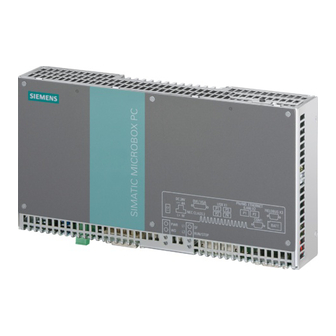
Description Overview The SIMATIC IPC427C provides high-level industrial performance. ● Compact design ● Maintenance-free operation ● High degree of ruggedness Figure 3-1 SIMATIC IPC427C SIMATIC IPC427C Operating Instructions, 04/2009, A5E02414743-01... -
Page 12: Applications
● Operating and visualization tasks with separate display / monitor solutions (information terminals, large-scale displays in automotive production) ● Data logging and processing (for example, system data logging, distributed process control) SIMATIC IPC427C Operating Instructions, 04/2009, A5E02414743-01... -
Page 13: Features
8 GB optional • Hard disk ≥ 80 GB SATA HD 2.5" optional SSD (Solid State Disk) ≥ 32 GB optional Floppy/CDROM drive Connected via external USB port USB stick Connected via external USB port SIMATIC IPC427C Operating Instructions, 04/2009, A5E02414743-01... - Page 14 LEDs under Windows XP and under RMOS3 under the FAQ at the Customer Support site Industry Automation and Drive Technologies - Homepage (http://www.siemens.com/automation/service&support). MUI: Multi Language User Interface; 5 languages (English, German, French, Spanish, Italian) SIMATIC IPC427C Operating Instructions, 04/2009, A5E02414743-01...
-
Page 15: Windows Embedded Standard 2009
Not available Windows .NET Messenger Available V 4.7 Available V 4.7 Code pages/User Available Selection available Location/Keyboard Disk Management Services Available Available Windows Installer Service Available V 3.1 Available V 3.1 Class Installer Available Available SIMATIC IPC427C Operating Instructions, 04/2009, A5E02414743-01... - Page 16 Activation of "HORM" and creation of a "Hiber File" When "HORM" is activated, the "Hibernate" function can be used for Windows Embedded Standard 2009: • EWFMGR C: /activatehorm "Hibernate" is activated following a restart. The system then always boots from this file. SIMATIC IPC427C Operating Instructions, 04/2009, A5E02414743-01...
-
Page 17: Design
Description 3.5 Design Design 3.5.1 External Design Device components Description ① Cover plate for Compact Flash module ② Connection elements ③ Status displays SIMATIC IPC427C Operating Instructions, 04/2009, A5E02414743-01... -
Page 18: Connection Components
The minimum conductor cross-section may not be less than 2,5 mm Location of the connection elements (second COM interface) Designation Description ① COM2 Serial port (RS232) 9-pin Cannon connector SIMATIC IPC427C Operating Instructions, 04/2009, A5E02414743-01... -
Page 19: Operator Controls
The On/Off switch does not disconnect the device from the supply voltage. Position of on/off switch Description ① The on/off switch turns off the output voltages of the power supply but not disconnect from the supply system. The delivery condition is: Power switch turned off. SIMATIC IPC427C Operating Instructions, 04/2009, A5E02414743-01... -
Page 20: Status Displays
Windows operating system in the section "Output register LED L1/L2". Example programs for addressing the LEDs under Windows XP and under RMOS are available under the FAQ at the Customer Support site Industry Automation and Drive Technologies - Homepage (http://www.siemens.com/automation/service&support). SIMATIC IPC427C Operating Instructions, 04/2009, A5E02414743-01... -
Page 21: Application Planning
(condensation). If condensation has developed on the device, wait at least 12 hours before you switch it on. SIMATIC IPC427C Operating Instructions, 04/2009, A5E02414743-01... -
Page 22: Unpacking And Checking The Delivery Unit
● Serial number: The serial number is available on the rating plate on the right side of the device. ● Order number of the device: The order number is located on the rating plate. SIMATIC IPC427C Operating Instructions, 04/2009, A5E02414743-01... - Page 23 Windows Embedded Standard 2009 or XP Professional and is affixed to the back of the device. Figure 4-1 COA Label Windows Embedded Standard 2009 Figure 4-2 COA Label Windows XP Pro for Embedded Systems SIMATIC IPC427C Operating Instructions, 04/2009, A5E02414743-01...
-
Page 24: Ambient And Environmental Conditions
● Do not cover the ventilation slots of the device. ● Always observe the mounting positions permitted for this device. ● The connected or built-in peripherals should not introduce a counter emf in excess of 0.5 V into the device. SIMATIC IPC427C Operating Instructions, 04/2009, A5E02414743-01... -
Page 25: Installing/Mounting
3 expansion modules • (max. load 9 W) in RAL: 0 to +50°C Notes: When mounted on a DIN rail, the device should be secured to prevent shifting (e.g. with a DIN rail ground terminal). SIMATIC IPC427C Operating Instructions, 04/2009, A5E02414743-01... - Page 26 The safety and installation instructions for the expansion modules should be followed if the device is expanded with PCI-104 / PC/104-plus modules. If necessary, the device should be installed in an enclosure that meets the requirements of paragraphs 4.6 and 4.7.3 of IEC/UL/EN/DINEN60950-1. SIMATIC IPC427C Operating Instructions, 04/2009, A5E02414743-01...
-
Page 27: Mounting Information
Industrial Control Equipment (UL508). A UL508 conform enclosure is therefore a mandatory requirement for approval or operation according to UL508. Mounting the device Mounting methods SIMATIC IPC427C can be mounted on DIN rails, with mounting brackets and in an upright position. SIMATIC IPC427C Operating Instructions, 04/2009, A5E02414743-01... -
Page 28: Mounting On Din Rails
5.4 Mounting on DIN rails Mounting on DIN rails Mounting the device on DIN rails Note Use of Siemens 35 mm standard mounting rail is recommended. Steps for mounting on DIN rails Set the device inclined on the upper DIN rail. - Page 29 Also see section Mounting with mounting brackets (Page 30). Removing the device from the DIN rail ● Push down the device until the clamps release it. ● Swing the device out of the rails. SIMATIC IPC427C Operating Instructions, 04/2009, A5E02414743-01...
-
Page 30: Mounting With Mounting Brackets
Steps for installing the mounting brackets Install the mounting brackets on the device. Note Required tools You need a TORX T20 screwdriver to remove the mounting clamps and mount the mounting brackets. SIMATIC IPC427C Operating Instructions, 04/2009, A5E02414743-01... - Page 31 Metal screws M 4: 4 mm diameter (min. 2 mm thick) 15 mm length WARNING Ensure that the wall or ceiling can hold four times the total weight of the device (including the cabinet brackets and additional expansion modules). SIMATIC IPC427C Operating Instructions, 04/2009, A5E02414743-01...
-
Page 32: Upright Mounting
With the available optional vertical mounting kit you have the possibility to implement a place saving installation. Mounting the vertical mounting bracket onto the device ① Device ② Screws ③ Vertical mounting bracket Note • Information on installation and operation is available in the supplement of the accessories. SIMATIC IPC427C Operating Instructions, 04/2009, A5E02414743-01... -
Page 33: Connecting
A counter emf greater than 0.5 V to ground on the + 3.3 VDC / + 5 VDC / + 12 VDC power rail due to a connected or integrated component can prevent normal operation or even destroy components of the device. SIMATIC IPC427C Operating Instructions, 04/2009, A5E02414743-01... -
Page 34: Connecting The 24 V Dc Power Supply
Steps for connecting the device to the 24 V DC power supply Switch off the 24 V DC power source. Connect the power supply using the plug (included in the package). Connect the PE conductor. SIMATIC IPC427C Operating Instructions, 04/2009, A5E02414743-01... -
Page 35: Protective Ground Connection
Connect the PE terminal (M4 thread) ① on the device to the PE conductor on the cabinet or system in which the PC will be installed. The minimum conductor cross-section may not be less than 2,5 mm SIMATIC IPC427C Operating Instructions, 04/2009, A5E02414743-01... -
Page 36: Usb Strain-Relief
1. Fasten the USB strain-relief ① to the device housing with an oval-head screw (M4 thread). 2. Thread the cable tie ② through the comb of the USB strain-relief to clamp the USB cable. SIMATIC IPC427C Operating Instructions, 04/2009, A5E02414743-01... -
Page 37: Commissioning
Commissioning Note before commissioning Factory state The SIMATIC IPC427C is available in the following versions: ● With the Windows Embedded Standard 2009 operating system (pre-installed on CompactFlash card, SSD drive or the hard disk) ● With the Windows XP Professional operating system (pre-installed on SSD drive or the hard disk) ●... -
Page 38: Commissioning - Windows Embedded Standard 2009
Windows Embedded Standard 2009 operating system is automatically opened when the startup routine is completed. Note To prevent data loss, it is advisable to create an image of your system partition after initial commissioning. SIMATIC IPC427C Operating Instructions, 04/2009, A5E02414743-01... - Page 39 The Enhanced Write Filter should be enabled following the installation of Windows Embedded Standard on a CompactFlash card or SSD drive. When this is enabled, the device can be switched off with the power switch by disconnecting the power supply. SIMATIC IPC427C Operating Instructions, 04/2009, A5E02414743-01...
-
Page 40: Commissioning - Windows Xp Professional
When you switch on the PC now, the user interface of the Windows XP Professional operating system is automatically opened when the startup routine is completed. Note To prevent data loss, it is advisable to create an image of your system partition after initial commissioning. SIMATIC IPC427C Operating Instructions, 04/2009, A5E02414743-01... -
Page 41: Setting Up The Language Selection For Windows Xp Professional / Embedded Standard
Start > Control Panel > Regional and Language Options Languages, tab Language used in menus and dialogs field. For the Regional and Language Options set the default as non-Unicode programs under Advanced in addition to the language for menus and dialogs. SIMATIC IPC427C Operating Instructions, 04/2009, A5E02414743-01... -
Page 42: Commissioning - Other Operating Systems
3 Select final boot medium In the BIOS Setup, select the medium on which the operating system has been installed. Additional information Further information about installation and commissioning is available in the documentation of the respective operating system. SIMATIC IPC427C Operating Instructions, 04/2009, A5E02414743-01... -
Page 43: Integration Into An Automation System
The serial port can be used for data communication (via terminal applications, for example). Additional information Additional information is available in the catalog and the online ordering system Industrial Automation and Drive Technologies (http://mall.automation.siemens.com). SIMATIC IPC427C Operating Instructions, 04/2009, A5E02414743-01... - Page 44 Integration into an Automation System 8.1 Overview SIMATIC IPC427C Operating Instructions, 04/2009, A5E02414743-01...
-
Page 45: Functions
SIMATIC PC DiagMonitor software is provided on CD (not included in the scope of delivery). It contains the monitoring software, the software for the stations to be monitored and a library for creating custom applications. SIMATIC IPC427C Operating Instructions, 04/2009, A5E02414743-01... -
Page 46: Temperature Monitoring/Display
The temperature error is retained in memory until temperatures have fallen below the thresholds and it is reset by one of the following measures: ● Acknowledgment of the error message by the monitoring software ● Restart of the device SIMATIC IPC427C Operating Instructions, 04/2009, A5E02414743-01... -
Page 47: Watchdog (Wd)
Normal mode: 94 ms, 210 ms, 340 ms, 460 ms, 590 ms, 710 ms, 840 ms and 960 ms. Macro mode: 2s, 4s, 6s, 8s, 16s, 32s, 48s and 64s. Note The watchdog is retriggered if the monitoring time is changed at the active watchdog (that is while the watchdog is running)! SIMATIC IPC427C Operating Instructions, 04/2009, A5E02414743-01... -
Page 48: Enhanced Write Filter (Ewf)
Modified files on drive C: Accept ewfmgr c: Display information about the EWF drive ewfmgr c: /h Display help Note The EWF commands affecting the write protection do not become active until after the next booting process. SIMATIC IPC427C Operating Instructions, 04/2009, A5E02414743-01... - Page 49 Start > Control Panel > Date and Time, remove the check mark from the "Automatically adjust clock for daylight saving changes" check box. 3. Enable EWF again (ewfmgr c: -enable) and reboot the system. SIMATIC IPC427C Operating Instructions, 04/2009, A5E02414743-01...
-
Page 50: File Based Write Filter (Fbwf)
• Observe the following syntax: Enter a space after the drive designation colon. • Changes for direct write access only take effect after rebooting. • Only existing files and folders can be entered in the exception list. SIMATIC IPC427C Operating Instructions, 04/2009, A5E02414743-01... - Page 51 /addexclusion C: \Test folder Remove file fbwfmgr /removeexclusion • C: \Test.txt Remove folder fbwfmgr /removeexclusion • C: \Test folder fbwfmgr /? Call up the help function For detailed instructions on FBWF go to (http://msdn.microsoft.com/en- us/library/aa940926(WinEmbedded.5).aspx) SIMATIC IPC427C Operating Instructions, 04/2009, A5E02414743-01...
-
Page 52: Sram Buffer Memory
A corresponding function is implemented there for using the CMOS-RAM under WinAC RTX. NOTICE If replacement of the battery takes longer than 30 seconds, the data saved in the CMOS RAM and in the buffered SRAM is lost. SIMATIC IPC427C Operating Instructions, 04/2009, A5E02414743-01... -
Page 53: Battery Monitoring
The information can be read from an I/O register and evaluated. When the first warning level is reached, the remaining service life of the battery for buffering CMOS data and buffered SRAM is at least 1 month. SIMATIC IPC427C Operating Instructions, 04/2009, A5E02414743-01... -
Page 54: Operation Without Monitor And Keyboard
A USB keyboard and mouse and an analog CRT monitor can be later connected for diagnostics. A digital DVI monitor can only be subsequently activated when the Windows Embedded Standard 2009 or Windows XP Professional operating system has fully booted. SIMATIC IPC427C Operating Instructions, 04/2009, A5E02414743-01... -
Page 55: Expansions And Configurations
● Cover and top cover plate: Torx T8 ● Hard disk mounting: Torx T10 ● Protective earth terminal: Torx T20 ● Spacing bolts PC/104: Hexagon head 5mm Preparation Isolate the device from power supply. SIMATIC IPC427C Operating Instructions, 04/2009, A5E02414743-01... - Page 56 Expansions and Configurations 10.1 Open the device (front panel) Open the device Steps in opening the device (front panel) Remove the six screws. Remove the front panel. SIMATIC IPC427C Operating Instructions, 04/2009, A5E02414743-01...
-
Page 57: Memory Expansion
ESD directives on handling electrostatically sensitive components ESD Guidelines (Page 147). Removing a memory module How to remove a memory module Open the device. Open the retention clamps ①. Tilt the memory module forward. Carefully remove the memory module. SIMATIC IPC427C Operating Instructions, 04/2009, A5E02414743-01... - Page 58 Carefully push the memory module back into the heat sink until it fully engages. Close the device. Display of the current memory configuration The new memory configuration is detected automatically. System RAM, Extended RAM and Cache SRAM are displayed during device startup. SIMATIC IPC427C Operating Instructions, 04/2009, A5E02414743-01...
-
Page 59: Installing Pci-104 / Pc/104 Plus Modules
When expanding the device with PCI-104 / PC/104 Plus modules, adhere to the safety and mounting regulations for the expansion modules. The device may be mounted in an enclosure that meets the requirements of Sections 4.6 and 4.7.3 of IEC/UL/EN/DINEN60950-1. SIMATIC IPC427C Operating Instructions, 04/2009, A5E02414743-01... -
Page 60: Mounting Pci-104 Or Pc/104 Plus Modules
Refer to the ESD directives on handling electrostatically sensitive components ESD Guidelines (Page 147). Plus Mounting PCI-104 or PC/104- modules Steps for mounting an expansion module Open the device (remove front panel). Insert module in slot ①. SIMATIC IPC427C Operating Instructions, 04/2009, A5E02414743-01... - Page 61 Follow the mounting procedure described in the previous section (steps 2 to 4). Plus Configuring/installing a PCI-104 or PC/104- module You may need to make settings in the BIOS Setup. For detailed information about installation, refer to the manufacturer documentation for the respective module. SIMATIC IPC427C Operating Instructions, 04/2009, A5E02414743-01...
-
Page 62: Installing/Removing Compact Flash Cards
Only use SIMATIC PC Compact Flash cards for industrial application. Note Only SIMATIC PC CompactFlash cards with product version number 02 (ES 02) can be used for this device. Figure 10-1 SIMATIC IPC CompactFlash® SIMATIC IPC427C Operating Instructions, 04/2009, A5E02414743-01... -
Page 63: Installing/Removing An Accessible Compact Flash Card
ESD directives on handling electrostatically sensitive components ESD Guidelines (Page 147). Opening the module receptacle Steps for opening the module receptacle Turn the cover plate ① of the module receptacle 180 degrees counter- clockwise. SIMATIC IPC427C Operating Instructions, 04/2009, A5E02414743-01... - Page 64 The Compact Flash slot is coded against reversed insertion. Insert it so that its upper side (label side) is facing the front panel of the device. CAUTION If the Compact Flash card meets resistance, flip it over. Never insert the CompactFlash card with force. SIMATIC IPC427C Operating Instructions, 04/2009, A5E02414743-01...
- Page 65 10.4 Installing/Removing Compact Flash Cards Removing the Compact Flash card Steps for removing a Compact Flash card Open the module receptacle. Press the eject button ① and remove the CompactFlash card. Close the module receptacle again. SIMATIC IPC427C Operating Instructions, 04/2009, A5E02414743-01...
-
Page 66: Installing/Removing A Built-In Compact Flash Card
Press the eject button ① and carefully remove the CompactFlash card from the holder. Fasten the cover plate again. To install, carry out the above steps in reverse order. SIMATIC IPC427C Operating Instructions, 04/2009, A5E02414743-01... -
Page 67: Maintenance And Service
UL approval of the device only applies when the UL-approved components are operated taking the "Conditions of Acceptability" into consideration. No liability can be accepted for impairment of functions caused by the use of third-party devices or components. SIMATIC IPC427C Operating Instructions, 04/2009, A5E02414743-01... -
Page 68: Preventive Maintenance
To maintain high system availability, we recommend the preventative exchange of those PC components that are subject to wear. The table below indicates the intervals for this exchange. Component Exchange interval: Hard disk 3 years CMOS backup battery 5 years SIMATIC IPC427C Operating Instructions, 04/2009, A5E02414743-01... -
Page 69: Replacing Hard Disk Or Ssd Drive
2. Unplug all peripherals (mouse, keyboard, monitor, for example) from the device. Removing drives NOTICE Check the ESD Guidelines (Page 147). How to remove a drive Remove the four screws of the cover plate and remove it SIMATIC IPC427C Operating Instructions, 04/2009, A5E02414743-01... - Page 70 Carefully remove the drive from the enclosure. Take the drive out of the holder. Installing a drive Carry out the described tasks in the reverse order. SIMATIC IPC427C Operating Instructions, 04/2009, A5E02414743-01...
-
Page 71: Replace The Backup Battery
A list in which you can note this information is available in the BIOS description. 2. Disconnect the device from the power supply. Tool You will need a TORX T8 screwdriver to open the battery compartment. SIMATIC IPC427C Operating Instructions, 04/2009, A5E02414743-01... - Page 72 Close the battery compartment. Reconfiguring the BIOS Setup If the battery replacement takes longer than 30 seconds, the configuration data of the device will be lost. You will have to reconfigure the BIOS setup in this case. SIMATIC IPC427C Operating Instructions, 04/2009, A5E02414743-01...
-
Page 73: Reinstalling The Operating System
You require a USB keyboard and a USB CD-ROM drive to reinstall the operating system. Before performing the new installation, you should check the date and time set in the BIOS Setup (Page 117) and correct it if necessary. SIMATIC IPC427C Operating Instructions, 04/2009, A5E02414743-01... -
Page 74: Restoring The Software To Factory State Using The Restore Dvd
2. Insert the Restore CD/DVD in the drive and reboot the device. When the BIOS message appears, press Press <F2> to enter Setup or <ESC> to show the Boot menu the F2 key. 3. Select the Boot menu and move the entry "CD-ROM Drive" to the first position. SIMATIC IPC427C Operating Instructions, 04/2009, A5E02414743-01... - Page 75 Note The "Legacy USB Support" option has to be set to "Enabled" in the Advanced menu of the BIOS so that the device can address a USB CD-ROM drive. SIMATIC IPC427C Operating Instructions, 04/2009, A5E02414743-01...
-
Page 76: Windows Xp Professional
The Recovery CD is included in the scope of delivery for Windows XP Professional. Note You will need a USB keyboard in order to reinstall the operating system. Before performing the new installation, you should reset the date and time set in the BIOS Setup (Page 117). SIMATIC IPC427C Operating Instructions, 04/2009, A5E02414743-01... -
Page 77: Restoring The Software To Factory State Using The Restore Dvd
Note The "Legacy USB Support" option has to be set to "Enabled" in the Advanced menu of the BIOS so that the device can address a USB DVD-ROM drive. SIMATIC IPC427C Operating Instructions, 04/2009, A5E02414743-01... - Page 78 Start > Control Panel > Regional and Language Options Languages, tab Language used in menus and dialogs field. For the Regional and Language Options set the default as non-Unicode programs under Advanced in addition to the language for menus and dialogs. SIMATIC IPC427C Operating Instructions, 04/2009, A5E02414743-01...
-
Page 79: Setting Up The Operating System Via The Recovery Cd/Dvd
● To install the selected partition, select "ENTER" ● To create a new partition in an unpartitioned area, press C. ● To delete the selected partition, press D. Note The on-screen instructions are in English. SIMATIC IPC427C Operating Instructions, 04/2009, A5E02414743-01... - Page 80 Start > Control Panel > Regional and Language Options Languages, tab Language used in menus and dialogs field. For the Regional and Language Options set the default as non-Unicode programs under Advanced in addition to the language for menus and dialogs. SIMATIC IPC427C Operating Instructions, 04/2009, A5E02414743-01...
-
Page 81: Partitioning Data Media
Remainder NTFS (not compressed) To restore the original partition to its factory state, we recommend the software tool SIMATIC PC/PG Image Creator. Detailed information about using this tool is available in the manufacturer documentation. SIMATIC IPC427C Operating Instructions, 04/2009, A5E02414743-01... -
Page 82: Setting Up The Partitions Under Windows Xp Professional
Remainder NTFS (not compressed) To restore the original partition to its factory state, we recommend the software tool SIMATIC PC/PG Image Creator. Detailed information about using this tool is available in the manufacturer documentation. SIMATIC IPC427C Operating Instructions, 04/2009, A5E02414743-01... -
Page 83: Installing Drivers And Software
3. Select "Drivers & Updates" from the index. 4. Select the operating system in "Drivers & Updates". 5. Install the required driver. NOTICE For new Windows XP Professional installations, the chipset driver must be installed before you install any other drivers. SIMATIC IPC427C Operating Instructions, 04/2009, A5E02414743-01... -
Page 84: Installing Updates
NOTICE Before you install new drivers or operating system updates at Windows XP Professional MUI versions, the regional settings for menus and dialogs and the default language have to be reset to US English. SIMATIC IPC427C Operating Instructions, 04/2009, A5E02414743-01... -
Page 85: Performing A Bios Update
Download from BIOS update Check regularly if updates are available for download to your device. You can find the downloads in the Internet (http://www.siemens.com/asis) in the "Support" tab under "Tools & Downloads"´. Using the global search function, you can then also search for any downloads you require. -
Page 86: Data Backup
Compact Flash cards, of HDDs and of individual partitions (images.) The Image Creator only supports the burning of DVD media. The software is available at the Siemens A&D online ordering system (http://www.siemens.com/automation/mall). For detailed information about SIMATIC PC/PG Image Creator, refer to the corresponding product documentation. -
Page 87: Alarm, Error And System Messages
No operating system installed • Incorrect active boot partition • Wrong boot drive settings in SETUP • Keyboard controller error Controller error. Contact your technical support team. Smart error Hard disk reports pending failure through S.M.A.R.T. SIMATIC IPC427C Operating Instructions, 04/2009, A5E02414743-01... - Page 88 Alarm, error and system messages 12.1 Boot error messages SIMATIC IPC427C Operating Instructions, 04/2009, A5E02414743-01...
-
Page 89: Troubleshooting/Faqs
Install a suitable driver; the correct driver can often be downloaded does not have a suitable from the homepage of the device's manufacturer. driver for the USB device. The EWF for Windows Embedded Standard 2009 must first be disabled for this purpose. SIMATIC IPC427C Operating Instructions, 04/2009, A5E02414743-01... -
Page 90: Problems When Using Modules Of Third-Party Manufacturers
PC. If the error no longer occurs, the third- levels are not adhered to party module was the cause of the fault. Replace this module with a Siemens module or contact the module Different connector pin •... -
Page 91: Technical Specifications
The generation of the 24 DC V supply voltage by the line-side SV must be made as functional extra-low voltage with safe electrical isolation according to IEC 60364-4-41 or as SELV in conformity to IEC/UL/EN/DIN-EN 60950-1 and LPS / NEC Class 2. SIMATIC IPC427C Operating Instructions, 04/2009, A5E02414743-01... - Page 92 Operating mode: Max. 10°C/h; Storage: 20°C/h; no condensation Relative humidity tested to IEC 60068-2-78, IEC 60068-2-30 - Operation 5% to 80% at 25° C (no condensation) -Storage/transport 5% to 95% at 25° C (no condensation) SIMATIC IPC427C Operating Instructions, 04/2009, A5E02414743-01...
- Page 93 Intel GMA4500 Graphics memory 8 - 512 MB Shared Memory Resolutions/frequencies/color depth CRT: 640 x 480 to 1920 x 1200 / 60 - 120Hz DVI-LCD: 640 x 480 to 1920 x 1200 / 60Hz SIMATIC IPC427C Operating Instructions, 04/2009, A5E02414743-01...
- Page 94 YELLOW SF (Group fault) Can be controlled by controller program (e.g. WinAC) L2 (LED 2) Can be controlled by user programs YELLOW GREEN STOP GREEN Can be controlled by controller program (e.g. WinAC) YELLOW SIMATIC IPC427C Operating Instructions, 04/2009, A5E02414743-01...
-
Page 95: Power Requirements Of The Components
0.5 A 0.5 A 1) The total load for PCI-104 and USB expansion is max. 15W. NOTICE Device can overheat! For thermal reasons, a 3 watt power loss per PCI/104 slot should not be exceeded. SIMATIC IPC427C Operating Instructions, 04/2009, A5E02414743-01... -
Page 96: Integrated Dc Power Supply
2.5" hard disk 100 mA Expansion USB 1) max. 500 mA max. 12 W Expansion PCI-104 1) max. 460 mA max. 11 W 1) The total load for PCI-104 and USB expansion is max. 15W. SIMATIC IPC427C Operating Instructions, 04/2009, A5E02414743-01... -
Page 97: Dimension Drawings
● Dimensional drawings of the device with expansion frames (Page 102) ● Dimension drawing of the blanking plate (Page 103) Note The dimensions are always given in in mm and inch (above: Millimeter, below: Inch SIMATIC IPC427C Operating Instructions, 04/2009, A5E02414743-01... -
Page 98: Dimension Drawings Of The Device
Dimension drawings 15.2 Dimension drawings of the device 15.2 Dimension drawings of the device Figure 15-1 Dimensional drawing of the device: Front view Figure 15-2 Dimensional drawing of the device: Side view SIMATIC IPC427C Operating Instructions, 04/2009, A5E02414743-01... -
Page 99: Dimension Drawings Of The Device With Mounting Brackets
Dimension drawings 15.3 Dimension drawings of the device with mounting brackets 15.3 Dimension drawings of the device with mounting brackets Figure 15-3 Dimensional drawing of the device with mounting brackets Front view and top view SIMATIC IPC427C Operating Instructions, 04/2009, A5E02414743-01... - Page 100 Dimension drawings 15.3 Dimension drawings of the device with mounting brackets Figure 15-4 Dimensional drawing of the device with mounting brackets Side view SIMATIC IPC427C Operating Instructions, 04/2009, A5E02414743-01...
-
Page 101: Dimensional Drawings Of The Device With Vertical Mounting Angles
Dimension drawings 15.4 Dimensional drawings of the device with vertical mounting angles 15.4 Dimensional drawings of the device with vertical mounting angles Figure 15-5 Dimensional drawings of the device with vertical mounting brackets SIMATIC IPC427C Operating Instructions, 04/2009, A5E02414743-01... -
Page 102: Dimensional Drawings Of The Device With Expansion Frames
Dimension drawings 15.5 Dimensional drawings of the device with expansion frames 15.5 Dimensional drawings of the device with expansion frames Figure 15-6 Dimensional drawings of the device with expansion frames SIMATIC IPC427C Operating Instructions, 04/2009, A5E02414743-01... -
Page 103: Dimension Drawing Of The Blanking Plate
Dimension drawings 15.6 Dimension drawing of the blanking plate 15.6 Dimension drawing of the blanking plate Figure 15-7 Dimensional drawing of the blinding plate SIMATIC IPC427C Operating Instructions, 04/2009, A5E02414743-01... - Page 104 Dimension drawings 15.6 Dimension drawing of the blanking plate SIMATIC IPC427C Operating Instructions, 04/2009, A5E02414743-01...
-
Page 105: Detailed Descriptions
Figure 16-1 Internal layout of the device ① Slot for a memory module ④ Motherboard Plus ② Slot for up to three PCI-104 or PC/104- ⑤ DC/DC converter modules ③ Slot for Compact Flash card SIMATIC IPC427C Operating Instructions, 04/2009, A5E02414743-01... -
Page 106: Technical Features Of The Motherboard
1.2 GHz, 3 MB SLC Memory DDR 3 SO-DIMM module 512 MB / 1024 MB / 2048 MB / 4096 MB Graphics Intel GMA4500 8 - 512 MB graphics memory taken dynamic from RAM SIMATIC IPC427C Operating Instructions, 04/2009, A5E02414743-01... -
Page 107: External Ports
Pin no. Short description Description Data carrier detect (I) Received data (I) Transmitted data (O) Data terminal ready (O) Ground Data set ready (I) Request to send (O) Clear to send (I) Incoming call (I) SIMATIC IPC427C Operating Instructions, 04/2009, A5E02414743-01... -
Page 108: Dvi-I
Analog red signal (O) Analog green (G) Analog green signal (O) Analog blue (B) Analog blue signal (O) Analog horizontal sync (HSYNC) Analog horizontal sync signal (O) Analog ground (analog R, G, & Analog ground return) (GND) SIMATIC IPC427C Operating Instructions, 04/2009, A5E02414743-01... -
Page 109: Ethernet
USB port, 4 channel high current Pin no. Short description Description USB_P5V_fused (O) + 5 V (fused) for external USB interface USB_D0M (I/O) Data+, USB channel 0 USB_D0P (I/O) Data-, USB channel 0 USB_GND Ground for external USB interface SIMATIC IPC427C Operating Instructions, 04/2009, A5E02414743-01... -
Page 110: Profibus
CAN bus signal (L active) CAN_GND CAN station ground Reserved Reserved Reserved CAN H CAN bus signal (H active) Reserved Reserved NOTICE The permitted maximum length of the CAN bus cable is 30 meters. SIMATIC IPC427C Operating Instructions, 04/2009, A5E02414743-01... -
Page 111: Internal Ports
26, 25 CD1#, CD2# Card detect (not connected) 33, 40 VS1#, VS2# Voltage sense (not connected) DMARQ DMA request (input) DMACK# DMA acknowledge (output) Write enable 1, 50 Ground 13, 38 + 5V power SIMATIC IPC427C Operating Instructions, 04/2009, A5E02414743-01... -
Page 112: Or Pc/104-Plus Interface (Pci Part)
AD24 C/BE3# VI/O IDSEL3 = AD31 AD26 AD25 AD29 AD28 AD27 AD30 AD31 REQ0# REQ1# VI/O REQ2# GNT0# GNT1# VI/O GNT2# CLK0 CLK1 CLK2 CLK3 INTD# RST# +12V INTA# INTB# INTC# -12V Reserved Reserved SIMATIC IPC427C Operating Instructions, 04/2009, A5E02414743-01... -
Page 113: Bios Setup
Your device configuration is preset for operating with the included software. You should only change the default values if you have modified the technical configuration your device, or if a fault occurs when the unit is powered up. SIMATIC IPC427C Operating Instructions, 04/2009, A5E02414743-01... -
Page 114: Starting Bios Setup
On completion of the POST, the BIOS gives you the opportunity of starting the SETUP program. The following message appears on the screen: PRESS F2 go to Setup Utility or Press ESC go to Boot Manager 2. Press F2 key as long as BIOS prompt appears on screen. SIMATIC IPC427C Operating Instructions, 04/2009, A5E02414743-01... -
Page 115: Bios Setup Menus
SETUP item from the "Item-specific help" part of the respective menu. Figure 16-2 BIOS SETUP menu (example) ① Header ④ Help window ② Menu bar ⑤ Command line ③ Selectable submenu SIMATIC IPC427C Operating Instructions, 04/2009, A5E02414743-01... - Page 116 Security functions are set here, for example, a password. Boot This is where the boot priority is specified. Version Information about the programming device (for example, release status) can be found here. Exit Used for terminating and saving. SIMATIC IPC427C Operating Instructions, 04/2009, A5E02414743-01...
-
Page 117: Main Menu
Type of installed drives Serial ATA Port 1 Type of installed drives Boot options Used for setting the boot options Keyboard Features Used for setting the keyboard interface (Numlock) Hardware Options Used for setting the hardware options SIMATIC IPC427C Operating Instructions, 04/2009, A5E02414743-01... - Page 118 This field shows the transmission speed of the interface. The displayed value depends on the Ultra DMA ATA-33 type of drive connected. Ultra DMA ATA-66 Exit the submenu by pressing ESC. Ultra DMA ATA-100 SIMATIC IPC427C Operating Instructions, 04/2009, A5E02414743-01...
- Page 119 Booting is stopped if any error except a keyboard error keyboard occurs All without Stop at any error, but not with a keyboard or S.M.A.R.T kb/smart storage media error. Diagnostic screen Shows the diagnostics messages on the monitor during booting. SIMATIC IPC427C Operating Instructions, 04/2009, A5E02414743-01...
- Page 120 Detailed descriptions 16.2 BIOS Setup "Keyboard Features" submenu Figure 16-6 "Keyboard Features" submenu Numlock Switches Numlock on or off following power on. SIMATIC IPC427C Operating Instructions, 04/2009, A5E02414743-01...
- Page 121 Image Creator), use the first Ethernet interface and disable the second Ethernet interface in BIOS Setup. This is practical because some programs use the second Ethernet interface because it is the first one found on the PCI bus. SIMATIC IPC427C Operating Instructions, 04/2009, A5E02414743-01...
-
Page 122: Advanced Menu
USB keyboard or mouse. SafeCard functions Enabled Watchdog reset is enabled. Disabled Watchdog reset is disabled. The relevant driver and the application must be started for operation of the monitoring functions. SIMATIC IPC427C Operating Instructions, 04/2009, A5E02414743-01... - Page 123 COM 1 or COM 2 is always disabled. Auto BIOS switches on the COM. Resources are assigned in the OS per reconfiguration. Enabled COM 1 or COM 2 is always enabled. BIOS assigns resources to COM. SIMATIC IPC427C Operating Instructions, 04/2009, A5E02414743-01...
- Page 124 Serial ATA Ports 0/1 work in AHCI Mode (only relevant for IPC427C). AHCI OpRom Serial ATA Ports 0/1/4/5 work in AHCI Mode with the Support ROM support option (setting for Panel PC; not relevant for IPC427C). SIMATIC IPC427C Operating Instructions, 04/2009, A5E02414743-01...
-
Page 125: Security Menu
All setup entries can be changed, except for the supervisor password. Set User This field opens the password input dialog. Logged on users can change the Password password, or clear and deactivate it by pressing "Return." SIMATIC IPC427C Operating Instructions, 04/2009, A5E02414743-01... -
Page 126: Boot Menu
Detailed descriptions 16.2 BIOS Setup 16.2.7 Boot menu This menu allows you to assign a priority for the boot devices. Figure 16-12 "Boot" menu SIMATIC IPC427C Operating Instructions, 04/2009, A5E02414743-01... - Page 127 Detailed descriptions 16.2 BIOS Setup Legacy Specifies the boot sequence for boot devices with Legacy operating systems. Figure 16-13 "Legacy" submenu SIMATIC IPC427C Operating Instructions, 04/2009, A5E02414743-01...
- Page 128 This screen shows all possible legacy boot types. The boot type with highest boot priority is shown at the top. To change the sequence: Select the boot source with the ↑↓ keys, move to the desired position with + or -. SIMATIC IPC427C Operating Instructions, 04/2009, A5E02414743-01...
- Page 129 Detailed descriptions 16.2 BIOS Setup Note You can open the Boot menu and select the boot volume by pressing the ESC key during system startup. SIMATIC IPC427C Operating Instructions, 04/2009, A5E02414743-01...
-
Page 130: Version Menu
Detailed descriptions 16.2 BIOS Setup 16.2.8 Version menu Keep this information at hand if customer support has technical questions about your system. Figure 16-15 Version menu (example) SIMATIC IPC427C Operating Instructions, 04/2009, A5E02414743-01... -
Page 131: Exit Menu
Profiles Standard The BIOS settings are backed up to buffered CMOS User The BIOS settings are saved in the non-volatile FLASH memory. Manufacturer This setting is only used for production purposes. Do not use. SIMATIC IPC427C Operating Instructions, 04/2009, A5E02414743-01... -
Page 132: Default Bios Setup Entries
All without keyboard Diagnostic screen Enabled Keyboard Features Numlock Hardware Options PCI - MPI/DP Enabled Internal CAN Enabled CAN bus I/O address 5400 On-board Ethernet 1 Enabled Ethernet 1 Address 00.0E.8C.xxxxxx Ethernet 1 Remote Boot Disabled SIMATIC IPC427C Operating Instructions, 04/2009, A5E02414743-01... - Page 133 Supervisor Password Not installed User password Not installed Set Supervisor Password Power on password User Access Level Set User Password Boot Legacy Boot Devices EFI Boot Devices Legacy Boot Type Order Boot menu Standard SIMATIC IPC427C Operating Instructions, 04/2009, A5E02414743-01...
- Page 134 SIMATIC PC IPC427C PROFIBUS BIOS Version V12.01.xx BIOS Number A5E02316088-ES0xx InsideH20 Version Montevina.03.56.37.20xx MPI / DP Firmware ID FPGA Revision ID Processor Type Intel® Core™2 Duo CPU U9300 @ 1.20GHz CPU ID 00676 Code Revision SIMATIC IPC427C Operating Instructions, 04/2009, A5E02414743-01...
-
Page 135: System Resources
You can view the current configuration of system resources or possible conflicts with the following operating systems: msinfo32 Windows Embedded Start > Run : In the Open dialog, enter and confirm with OK Standard 2009 SIMATIC IPC427C Operating Instructions, 04/2009, A5E02414743-01... -
Page 136: System Resources Used By The Bios/Dos
IRQ21 PCI104 Slot 2 PCI exclusive IRQ22 PCI104 Slot 3, USB-UHCI Controller 1-3 (USB1.1), PCI shared USB-EHCI Controller 1 (USB2.0) IRQ23 PCI104 Slot 3, USB-UHCI Controller 4-6 (USB1.1), PCI shared USB-EHCI Controller 2 (USB2.0) SIMATIC IPC427C Operating Instructions, 04/2009, A5E02414743-01... -
Page 137: I/O Address Areas
CAN base address register (Watchdog enable register bit 2=1) (Page 139) I/O 404Eh - 404Fh Output register LED 1/2 and SF LED / RUN/STOP LED (Page 140) I/O 50Fh Battery status register (read-only) (Page 140) SIMATIC IPC427C Operating Instructions, 04/2009, A5E02414743-01... -
Page 138: Watchdog Enable Register / 066H Select Register (Read/Write, Address 062H)
Watchdog trigger register (read only, address 066h) Watchdog trigger register The watchdog is triggered by a read action (address 066h) by this register. The result of the read access can be disregarded (i.e., dummy read). SIMATIC IPC427C Operating Instructions, 04/2009, A5E02414743-01... -
Page 139: Can Base Address Register (Write Only, Address 066H)
/ 066h select register therefore must be selected before access. Meaning of the bits CAN base address register (write only, address 066h, Address register selection 1) Description Reserved (Write: 00) Reserved (Write:01) Sets the high byte of the CAN base address 01nnnn00 SIMATIC IPC427C Operating Instructions, 04/2009, A5E02414743-01... -
Page 140: Output Register Led 1 / 2 (Read/Write, Address 404Eh)
The L1 and L2 LEDs indicate by flashing alternatively yellow the progress of the BIOS self- test during the device startup. When the BIOS self-test is completed, the L1 and L2 LEDs go dark. SIMATIC IPC427C Operating Instructions, 04/2009, A5E02414743-01... -
Page 141: Battery Status Tab (Read-Only, Address 50Fh)
Meaning of the bits Battery status register (read-only, address 50Fh) Description CMOS battery capacity is still sufficient. CMOS battery capacity is exhausted (remaining capacity is sufficient for approx. one month) CMOS battery is empty SIMATIC IPC427C Operating Instructions, 04/2009, A5E02414743-01... -
Page 142: Sram Address Register
SRAM address register PCI register address: PCI register content: Length of the memory area SRAM base address register SRAM memory address (default) 8010 2010h 9040 0000h 20 0000h Address is assigned dynamically (depending on device) SIMATIC IPC427C Operating Instructions, 04/2009, A5E02414743-01... -
Page 143: Appendix
Connecting peripherals Noise immunity requirements to EN 61000-6-2 / IEC 61000-6-2 are met if connected peripherals are suitable for industrial applications. Peripheral devices are only be connected via shielded cables. SIMATIC IPC427C Operating Instructions, 04/2009, A5E02414743-01... -
Page 144: Certificates And Approvals
A.2 Certificates and approvals Certificates and approvals DIN ISO 9001 certificate The Siemens quality management system for all production processes (development, production and sales) meets DIN ISO 9001:2000 requirements. This has been certified by DQS (the German society for the certification of quality management systems). - Page 145 This Class A digital apparatus complies with Canadian ICES-003. Avis Canadian Cet appareil numérique de la classe B est conforme à la norme NMB-003 du Canada. AUSTRALIA This product meets the requirements of the AS/NZS CISPR 22. SIMATIC IPC427C Operating Instructions, 04/2009, A5E02414743-01...
-
Page 146: Service And Support
Industry Automation and Drive Technologies - Homepage (http://www.siemens.com/automation/service&support) After-sales information system for SIMATIC PC / PG Information about contacts, drivers, and BIOS updates, FAQs and Customer Support can be found at: After-sales information system for SIMATIC PC/PG (http://www.siemens.com/asis) SIMATIC IPC427C Operating Instructions, 04/2009, A5E02414743-01... -
Page 147: Esd Guidelines
The electrostatic discharge current may lead to latent failure of a module, that is, this damage may not be significant immediately, but in operation may cause malfunction. SIMATIC IPC427C Operating Instructions, 04/2009, A5E02414743-01... - Page 148 In this way, the discharged energy can not affect the sensitive devices. Discharge your body before you start taking any measurements on a module. Do so by touching grounded metallic parts. Always use grounded measuring instruments. SIMATIC IPC427C Operating Instructions, 04/2009, A5E02414743-01...
-
Page 149: List Of Abbreviations
Clock signal for controllers CMOS Complementary Metal Oxide Complementary metal oxide semiconductors Semiconductors Certificate of authentication Microsoft Windows Product Key Certificate of License License authorization Communications Port Term for the serial interface Communication Processor Communication computer SIMATIC IPC427C Operating Instructions, 04/2009, A5E02414743-01... - Page 150 Control character Enhanced Write Filter Frequently Asked Questions FAQs FAT 32 File Allocation Table 32-bit 32-bit file allocation table FBWF File-Based Write Filter Floppy disk Disk drive, 3.5" Front Side Bus Ground Chassis ground SIMATIC IPC427C Operating Instructions, 04/2009, A5E02414743-01...
- Page 151 Mean Time Between Failures Multilanguage User Interface Language localization in Windows Not Applicable NAMUR Normenarbeitsgemeinschaft for Mess- und Regelungstechnik in der chemischen Industrie (standardization body for instrumentation and control technology in the chemicals industry) SIMATIC IPC427C Operating Instructions, 04/2009, A5E02414743-01...
- Page 152 Safety extra low voltage Second Level Cache SMART Self Monitoring Analysis and Reporting Hard disk error diagnostics program Technology Short Message Service Short message via telecommunication network SNMP Simple Network Management Protocol Network protocol SIMATIC IPC427C Operating Instructions, 04/2009, A5E02414743-01...
- Page 153 Loss-free file format for audio data Watchdog Program monitoring with error detection and alarming. WLAN Wireless LAN LWireless local area network Wake on Local Area Network World Wide Web Extended Graphics Array Graphic standard, maximum resolution 1024x768 pixels. SIMATIC IPC427C Operating Instructions, 04/2009, A5E02414743-01...
- Page 154 List of abbreviations C.1 Abbreviations SIMATIC IPC427C Operating Instructions, 04/2009, A5E02414743-01...
-
Page 155: Glossary
Boot disk A boot disk is a bootstrap disk with "Boot" sector. This can be used to load the operating system from the disk. Cache High-speed access buffer for interim storage (buffering) of requested data. SIMATIC IPC427C Operating Instructions, 04/2009, A5E02414743-01... - Page 156 . This is done either by copying the configuration files supplied with the module or by manual configuration using the configuration utility. Controller Integrated hardware and software controllers that control the functions of certain internal or peripheral devices (for example, the keyboard controller). SIMATIC IPC427C Operating Instructions, 04/2009, A5E02414743-01...
- Page 157 Configurable write filter that allows you, for example, to boot Windows Embedded Standard from write-protected media (such as CD-ROM), to write protect individual partitions and adapt the performance of the file system to your needs (when using Compact Flash cards). SIMATIC IPC427C Operating Instructions, 04/2009, A5E02414743-01...
- Page 158 Hyper Threading HT technology (multi-threading) enables the parallel computing of processes. HT is only effective when all relevant system components, such as processors, operating systems and applications are supported. SIMATIC IPC427C Operating Instructions, 04/2009, A5E02414743-01...
- Page 159 The devices connected to a LAN are called nodes. The purpose of networks is the mutual use of files, printers or other resources. Legacy USB support Support of USB devices (e.g. mouse, keyboard) on the USB ports without driver. SIMATIC IPC427C Operating Instructions, 04/2009, A5E02414743-01...
- Page 160 Glossary License key The license key represents the electronic license stamp of a license. Siemens provides the license keys for protected software. License key disk The license key disk contains the authorizations or license keys required to enable protected SIMATIC software.
- Page 161 ISA (PC/104) and PCI (PC/104- Plus ). Software cannot usually detect a difference between them and normal desktop bus systems. Their advantage is the compact design and the resulting space they save. SIMATIC IPC427C Operating Instructions, 04/2009, A5E02414743-01...
- Page 162 Industrial Ethernet meets the requirements of industrial automation technology. Programmable controller (PLC) The programmable controllers (PLC) of the SIMATIC S5 system consist of a central controller, one or more CPUs, and various other modules (e.g. I/O modules). SIMATIC IPC427C Operating Instructions, 04/2009, A5E02414743-01...
- Page 163 It makes for permanent monitoring of important parameters and early detection of imminent problems. SATA Serial ATA Interface for hard disk drives and optical drives with serial data transmission rates of up to 300 Mbps. SIMATIC IPC427C Operating Instructions, 04/2009, A5E02414743-01...
- Page 164 V.24 is a standardized interface for data transfer. Printers, modems, and other hardware modules can be connected to a V.24 interface. Wake on LAN (WoL) Wake on Local area network. This function allows the PC to be started via the LAN interface. SIMATIC IPC427C Operating Instructions, 04/2009, A5E02414743-01...
- Page 165 The CTRL+ ALT+ DEL hotkey can be used to initiate a warm restart. WLAN Wireless LAN is a local network that transmits data via radio waves, infrared light or another wireless technology. Wireless LAN is mainly used for mobile computer applications in office or factory environments. SIMATIC IPC427C Operating Instructions, 04/2009, A5E02414743-01...
- Page 166 Glossary SIMATIC IPC427C Operating Instructions, 04/2009, A5E02414743-01...
-
Page 167: Index
DVI-I port, 108 COM1 port, 107 Commissioning Other operating systems, 42 Windows Embedded Standard 2009, 38 Windows XP Professional, 40 Electrostatic sensitive devices, 10 Compact Flash card EMC directive, 143 Installation/removal, 65 Enable register SIMATIC IPC427C Operating Instructions, 04/2009, A5E02414743-01... - Page 168 Ethernet, 18, 43 Updates, 84 ETHERNET, 18 Windows Embedded Standard 2009, 74 PROFIBUS, 18, 43 Windows XP Professional, 78 Internal components Order number, 22 Overview, 105 Internal interfaces, 111 IT communication, 43 Partitioning, 79 SIMATIC IPC427C Operating Instructions, 04/2009, A5E02414743-01...
- Page 169 Initial commissioning, 40 Startup, 54, 87 Partitioning the hard disk, 81, 82 Status displays, 94 Reinstalling the operating system, 76 Supply voltage, 91 System Date, 118 System partition, 74, 77 System resources, 135 System Time, 118 SIMATIC IPC427C Operating Instructions, 04/2009, A5E02414743-01...
- Page 170 Index SIMATIC IPC427C Operating Instructions, 04/2009, A5E02414743-01...