Vaisala HUMICAP HMP155 User Manual
Humidity and temperature probes
Hide thumbs
Also See for HUMICAP HMP155:
- User manual (102 pages) ,
- User manual (86 pages) ,
- Quick manual (2 pages)
Table of Contents
Advertisement
Advertisement
Table of Contents

Related Manuals for Vaisala HUMICAP HMP155


Summary of Contents for Vaisala HUMICAP HMP155
- Page 1 USER'S GUIDE Vaisala HUMICAP® Humidity and Temperature Probe HMP155 M210912EN-C...
- Page 2 English versions are applicable, not the translations. The contents of this manual are subject to change without prior notice. This manual does not create any legally binding obligations for Vaisala towards customers or end users. All legally binding obligations and agreements are included exclusively in the applicable supply contract or the General Conditions of Sale and General Conditions of Service of Vaisala.
-
Page 3: Table Of Contents
Getting Started ............... 23 RS-485 Interface ..............23 Serial Line Communication ........... 24 Installing the Driver for the USB Cable ....... 25 Terminal Application Settings..........26 List of Serial Commands ............. 28 Measurement Commands........... 30 R..................30 S ..................30 VAISALA ________________________________________________________________________ 1... - Page 4 USER'S GUIDE____________________________________________________________________ SEND [ADDR] ..............30 SDELAY .................30 SERI [BAUD][PARITY][DATA][STOP] ......31 #..................31 SMODE ................32 INTV ................32 Formatting Commands............33 FORM ................33 UNIT [M/N] ..............35 TIME ................35 Pressure Compensation Commands ........36 PRES and XPRES ............36 System Commands .............37 FILT [0.1…1] ..............37 ?..................38 HELP ................39 ERRS................40 VERS................40 RESET................40...
- Page 5 Accuracy of Dew point Measurement ......... 75 Inputs and Outputs ..............75 Mechanics ................76 Options and Accessories ............77 Dimensions in mm (inches) ..........78 HMP155 Probe..............78 Additional Temperature Probe ..........78 APPENDIX A CALCULATION FORMULAS ..............79 VAISALA ________________________________________________________________________ 3...
- Page 6 USER'S GUIDE____________________________________________________________________ List of Figures Figure 1 HMP155 Probe .................13 Figure 2 HMP155 with Additional T-probe..........14 Figure 3 HMP155 with Optional Connection Cover........15 Figure 4 HMP155 with T-probe Installed in DTR13........17 Figure 5 HMP155 Installed in DTR503 ...........18 Figure 6 HMP155 with T-Probe Installed in Stevenson Screen .....19 Figure 7 Wiring of HMP155 8-Pin Connector .........20...
-
Page 7: Chapter 1 General Information
This chapter provides general notes for the manual and the product. About This Manual This manual provides information for installing, operating, and ® maintaining Vaisala HUMICAP Humidity and Temperature Probe HMP155. Contents of This Manual This manual consists of the following chapters: - Chapter 1, General Information, provides general notes for the manual and the Humidity and Temperature Probe HMP155. -
Page 8: Version Information
Table 2 Related Manuals Manual Code Manual Name M210913EN Vaisala HUMICAP® Humidity and Temperature Probe HMP155 Quick Reference Guide Documentation Conventions Throughout the manual, important safety considerations are highlighted as follows: Warning alerts you to a serious hazard. If you do not read and follow... -
Page 9: Safety
Conformity is shown by compliance with the following standards: - EN 61326-1: Electrical equipment for measurement, control, and laboratory use – EMC requirements – for use in industrial locations. - EN 550022: Information technology equipment – Radio disturbance characteristics – Limits and methods of measurement. VAISALA ________________________________________________________________________ 7... -
Page 10: Recycling
United States and/or other countries. License Agreement All rights to any software are held by Vaisala or third parties. The customer is allowed to use the software only to the extent that is provided by the applicable supply contract or Software License Agreement. -
Page 11: Warranty
Please observe that any such warranty may not be valid in case of damage due to normal wear and tear, exceptional operating conditions, negligent handling or installation, or unauthorized modifications. Please see the applicable supply contract or Conditions of Sale for details of the warranty for each product. VAISALA ________________________________________________________________________ 9... - Page 12 USER'S GUIDE____________________________________________________________________ This page intentionally left blank. 10 _______________________________________________________________ M210912EN-C...
-
Page 13: Chapter 2 Product Overview
Chapter 2 __________________________________________________________ Product Overview CHAPTER 2 PRODUCT OVERVIEW This chapter introduces the features, advantages, and the product ® nomenclature of the Vaisala HUMICAP Humidity and Temperature Probe HMP155. Introduction to HMP155 The HMP155 probe provides reliable humidity and temperature measurement in a wide range of applications. -
Page 14: Basic Features And Options
USER'S GUIDE____________________________________________________________________ Table 4 Quantities Calculated by HMP155 Quantity Abbreviation Metric Non-Metric Unit Unit Dew point / Frost point ºC ºF Temperature (T Dew point Temperature (T ºC ºF Mixing ratio (x) g/kg gr/lb. Wetbulb temperature (T ºC ºF Basic Features and Options - Can be used to replace HMP45A/D, also in radiation shields ®... -
Page 15: Structure Of The Hmp155
Chapter 2 __________________________________________________________ Product Overview Structure of the HMP155 0801-070 Figure 1 HMP155 Probe The numbers refer to Figure 1 above. Filter Protective cover 8-Pin male connector (M12) VAISALA _______________________________________________________________________ 13... -
Page 16: Additional Temperature Probe Option
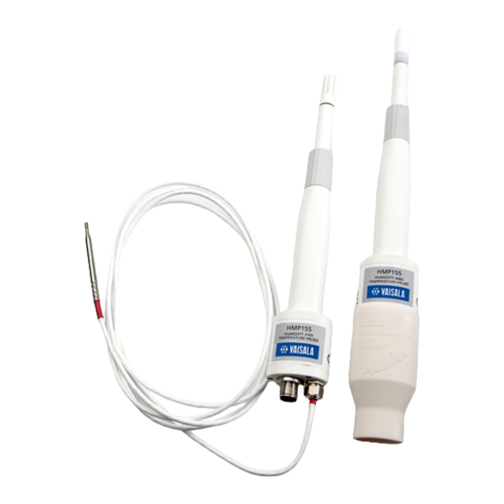
USER'S GUIDE____________________________________________________________________ Additional Temperature Probe Option 1206-038 Figure 2 HMP155 with Additional T-probe The active output version of HMP155 can be ordered with an additional temperature probe option, see Figure 2 above. When the additional T- probe is in use, the relative humidity value is calculated based on the T (dew point) value obtained from the humidity probe and the T value obtained from the T-probe. -
Page 17: Warmed Probe Option
HMP155 only produces dew point and mixing ratio output. Connection Cover Option 1206-039 Figure 3 HMP155 with Optional Connection Cover An optional connection cover is available for enhanced protection in wet environments such as coasts or rainforests. VAISALA _______________________________________________________________________ 15... - Page 18 USER'S GUIDE____________________________________________________________________ This page intentionally left blank. 16 _______________________________________________________________ M210912EN-C...
-
Page 19: Chapter 3 Installation
Installation in Radiation Shields In order to reach the maximum performance level of the HMP155 probe, Vaisala recommends installing the HMP155 in a radiation shield, for example in DTR503, in DTR13 or in a Stevenson screen. See Figure 4 below, Figure 5 on page 18 and Figure 6 on page 19. -
Page 20: Installation In Dtr503
USER'S GUIDE____________________________________________________________________ Installation in DTR503 0801-072 Figure 5 HMP155 Installed in DTR503 18 _______________________________________________________________ M210912EN-C... -
Page 21: Installation In Stevenson Screen
Chapter 3 _______________________________________________________________ Installation Installation in Stevenson Screen 0805-008 Figure 6 HMP155 with T-Probe Installed in Stevenson Screen VAISALA _______________________________________________________________________ 19... -
Page 22: 8-Pin Connector
USER'S GUIDE____________________________________________________________________ 8-Pin Connector Both the passive and active versions of HMP155 come with an 8-pin M12 male connector on the bottom of the probe. 0507-044 Figure 7 Wiring of HMP155 8-Pin Connector The pins of the connector for HMP155 passive output version in Figure 7 are (open end wire colors in brackets): PT100 (white) 0…1 V (brown)/RS-485-B... -
Page 23: Figure 8 Hmp155D Block Diagram And Wiring
The left side of Figure 9 below shows the HMP155A/E block diagram. The right side shows an example of connections. For the pin layout see Figure 7 on page 20. 1205-106 Figure 9 HMP155A/E Block Diagram and Wiring VAISALA _______________________________________________________________________ 21... -
Page 24: Temporary Rs-485 Connection Option
The active output version with two voltage channels includes also a solid RS-485 connection with dedicated signal pins that can be used as a temporary digital service port. However, Vaisala does not recommend the continuous, parallel use of both digital and analog outputs, because this may affect the temperature measurement accuracy due to increased power consumption and probe self-heating. -
Page 25: Chapter 4 Operation
This chapter contains information that is needed to operate this product. Getting Started ® After the Vaisala HUMICAP Humidity and Temperature Probe HMP155 has been connected to a power supply, the serial line and the analog outputs are operational depending on product model. -
Page 26: Serial Line Communication
USER'S GUIDE____________________________________________________________________ Serial Line Communication Connect the probe to a PC, for example, by using a USB cable (optional accessory item: 221040). Connect the USB cable to the 8-pin connector on the bottom of the probe. Before you can use the USB cable, you must install the provided USB driver on your PC, see Installing the Driver for the USB Cable on page 25. -
Page 27: Installing The Driver For The Usb Cable
COM port. There is no reason to uninstall the driver for normal use. However, if you wish to remove the driver files and all Vaisala USB cable devices, you can do so by uninstalling the entry for Vaisala USB Instrument Driver from the Add or Remove Programs (Programs and Features in Windows Vista) in the Windows Control Panel. -
Page 28: Terminal Application Settings
Select the Serial settings category, and check that the correct COM port is selected in the Serial line to connect to field. You can check which port the USB cable is using with the Vaisala USB Instrument Finder program that has been installed in the Windows Start menu. -
Page 29: Figure 10 Putty Terminal Application
Chapter 4 ________________________________________________________________ Operation 0903-025 Figure 10 PuTTY Terminal Application VAISALA _______________________________________________________________________ 27... -
Page 30: List Of Serial Commands
USER'S GUIDE____________________________________________________________________ List of Serial Commands Most of the commands listed below are relevant only in the digital output version of HMP155. These commands are marked with an * in the description column to make them easier to tell apart. The bold text in the brackets is the default setting. -
Page 31: Table 9 Calibration And Adjustment Commands
Set the result filtering HELP Lists the available commands PRES [hPa] Set the value for pressure compensations RESET Resets the probe. VERS Display the software version information XHEAT Sensor heating * XPRES [bar] Set the value for pressure compensations, temporarily VAISALA _______________________________________________________________________ 29... -
Page 32: Measurement Commands
USER'S GUIDE____________________________________________________________________ Measurement Commands Enter the R command to start the continuous output of measurements. This command starts a temporary RUN mode. To change to permanent RUN mode, use the SMODE command. Example: >r RH= 33.0 %RH T= 22.1 'C >... -
Page 33: Seri [Baud][Parity][Data][Stop]
>seri 4800 Baud P D S : 4800 E 7 1 > To force the settings 19200 baud, no parity, 8 data bits, 1 stop bit, enter the # command on the first three seconds after power-up. VAISALA _______________________________________________________________________ 31... -
Page 34: Smode
USER'S GUIDE____________________________________________________________________ The settings are temporary, and last only for a single session at a time. On the next connection HMP155 reverts to the settings last set with the SERI command. SMODE Use the SMODE command to set the user port to permanent STOP, RUN, POLL or SEND mode. -
Page 35: Formatting Commands
Probe status in 7 character field, for example: no heating probe heating active, power purge heating active, temperature purge cooling active, temperature sensor heating active, temperature SNUM Probe serial number TIME Time [hh:mm:ss] Example: >form "Temperature=" 5.2 t #r#n VAISALA _______________________________________________________________________ 33... -
Page 36: Table 14 Symbols Used In Form Checksum Equations
USER'S GUIDE____________________________________________________________________ >send Temperature= 24.23 > >form "Twet=" 6.3 tw U3 #t "T=" t U3 #r#n >send Twet= 11.290'C 24.231'C > >form 5.1 rh #t t #t tdf #r#n >send 15.6 24.2 -3.1 > FORM / command returns the default output format. The default output format depends on the device configuration. -
Page 37: Unit [M/N]
The time setting will not be stored in any memory. At reset or when the probe is turned off, the time will go back to 00:00:00. VAISALA _______________________________________________________________________ 35... -
Page 38: Pressure Compensation Commands
USER'S GUIDE____________________________________________________________________ Pressure Compensation Commands PRES and XPRES Use the PRES serial line command to set ambient pressure value for fixed pressure compensation. If the value is changed frequently, use the XPRES serial line command. Its value is cleared to 0.0 at reset; if it is set to other than 0, it overrides the setting given with the PRES command. -
Page 39: System Commands
FILT value 0.1 a new output is a combination of the previous output (90%) and the latest measurement (10%). FILT [xxx] where xxx = 0.1…1 where 1.0 = no filter and 0.1 = about 16 moving average Example: >filt Filter : 0.800 ? > VAISALA _______________________________________________________________________ 37... - Page 40 USER'S GUIDE____________________________________________________________________ Use the ? serial line command to check the current probe configuration. ?? command is similar but can also be used if the probe is in POLL mode. Example: >? HMP155 1.00 Serial number : C1230001 Batch number : B2350090 Module number : C4840248...
-
Page 41: Help
FILT value FORM 'format string' HELP INTV 0...255 s/min/h OPEN addr PRES bar PUR on/off RESET SDELAY 0...255 SEND addr SERI baud p d s SMODE stop/run/poll TIME hh:mm:ss UNIT m/n VERS XHEAT on/off XPRES bar > VAISALA _______________________________________________________________________ 39... -
Page 42: Errs
USER'S GUIDE____________________________________________________________________ ERRS Use the ERRS command to display probe error messages, see Table 15 on page 54. Example: >errs No errors > VERS Use the VERS command to display software version information. Example: >vers HMP155 1.01 > RESET Use the RESET command to reset the device. The user port switches to start-up output mode selected with SMODE command. -
Page 43: Analog Output Configuration Commands
Ch1 : 0 ... 1V > NOTE Analog output calibration is valid only for the factory settings. If you change the analog output mode with AMODE command, you must continue by entering the ACAL command, see ACAL on page 68. VAISALA _______________________________________________________________________ 41... -
Page 44: Asel
USER'S GUIDE____________________________________________________________________ ASEL Use the ASEL command to select the quantities and scaling for analog outputs of the HMP155. Note that the optional quantities can be selected only if they have been selected when ordering the device. Quantities and their abbreviations are listed in Table 3 on page 11 and Table 4 on page ASEL [CH1 CH2] [low1 high1 low2 high2] Where CH1 = Quantity of channel 1... -
Page 45: Atest
CH0ERR = Analog output CH1ERR = Analog output Example: >aerr Ch0 error out : 10.000V ? 0 Ch1 error out : 1.000V ? 0 > The error output value must be within the valid range of the output NOTE mode. VAISALA _______________________________________________________________________ 43... -
Page 46: Addr
USER'S GUIDE____________________________________________________________________ NOTE The error output value is outputted only when there are minor electrical faults such as humidity sensor damage. When there is a severe device malfunction, the error output value is not necessarily shown. ADDR Addresses are required only for POLL mode (see serial line command SMODE on page 31) and intended for multi-purpose RS485 buses. -
Page 47: Sensor Functions
Chemical purge function locks the output values for about 6 minutes. NOTE NOTE Avoid using the purge function in low (below freezing) temperatures. Low temperatures decrease the effectivity of purge. Also, the lower the temperature, the longer it takes for the sensor to return to normal functionality. VAISALA _______________________________________________________________________ 45... -
Page 48: Automatic Chemical Purge (Interval Purge)
USER'S GUIDE____________________________________________________________________ 0508-035 Figure 11 Decrease of Sensor Gain Automatic Chemical Purge (Interval Purge) When HMP155 leaves the factory the automatic chemical purge takes place repeatedly with the time intervals set in the factory, if this option is chosen. You can change the interval in which the purge takes place by using serial commands. -
Page 49: Starting And Configuring Chemical Purge
To activate the new interval settings immediately, reset the probe. NOTE When chemical purge in power-up is enabled, wait about 6 min after power-up before taking measurements. The output channels are locked for the first operation minutes to the initial measured values. VAISALA _______________________________________________________________________ 47... -
Page 50: Sensor Heating
USER'S GUIDE____________________________________________________________________ Sensor Heating This function is optionally available only in probes with ® ® HUMICAP HUMICAP sensors. It should be 180RC or 180C composite used only with the heated probe. The sensor heating is recommended for the high humidity environments where even small temperature differences can cause water to condense on the sensor. -
Page 51: Xheat
To see the current values, use the XHEAT * command. Example : >xheat * Extra heat RH limit 95 %RH Temperature 100 'C Duration > NOTE After the defined XHEAT duration, there is an additional cooling time of 10 seconds before outputs are updated. VAISALA _______________________________________________________________________ 49... - Page 52 USER'S GUIDE____________________________________________________________________ This page intentionally left blank. 50 _______________________________________________________________ M210912EN-C...
-
Page 53: Chapter 5 Maintenance
After removing the filter, check the O-ring and change it if necessary. See Figure 12 on page 53. Install a new filter on the probe. New filters can be ordered from Vaisala, see section Options and Accessories on page 77. VAISALA _______________________________________________________________________ 51... -
Page 54: Changing The Sensor
180C/180RC models, the temperature sensor is integrated with the relative humidity sensor. It is recommended that these type of sensors are changed by Vaisala Service. See section Product Returns on page 55. If you do change the sensor yourself, the instructions above apply, except now before removing the damaged sensor, you need to unsolder the connections from the temperature sensor pins. -
Page 55: Figure 12 Changing The Humicap 180/180R Sensors
Chapter 5 ______________________________________________________________ Maintenance 0802-159 ® Figure 12 Changing the HUMICAP 180/180R Sensors The following numbers refer to Figure 12 above: Filter O-ring ® HUMICAP sensor Pt100 temperature sensor VAISALA _______________________________________________________________________ 53... -
Page 56: Error States
- The serial port outputs stars (***) instead of measured values. You can also check the error message via the serial interface by using the ERRS command. In case of constant error, please contact Vaisala, see sections Technical Support and Product Returns on page 55 . -
Page 57: Technical Support
Chapter 5 ______________________________________________________________ Maintenance Technical Support For technical questions, contact the Vaisala technical support by e-mail at helpdesk@vaisala.com. Provide at least the following supporting information: - Name and model of the product in question - Serial number of the product... - Page 58 USER'S GUIDE____________________________________________________________________ This page intentionally left blank. 56 _______________________________________________________________ M210912EN-C...
-
Page 59: Calibration And Adjustment
NOTE Vaisala recommends that RH adjustment is carried out as a two-point adjustment. With one-point adjustment, the required accuracy can only be achieved if the actual measurement environment (RH and T) is the same as the one-point adjustment environment. -
Page 60: Figure 13 Hmp155 Adjustment Buttons
USER'S GUIDE____________________________________________________________________ 0801-076 Figure 13 HMP155 Adjustment Buttons The following numbers refer to Figure 13 above: Protective cover (unscrewed) Down button ADJ button Up button Protective plug (lifted up) There is a two-color indicator LED located under the protective plug and next to the Down button, see Figure 13 above. -
Page 61: Push-Button Calibration
Using the - and + buttons, make sure the A voltage is correct and press the ADJ button. Green indicator LED turns off and back on. Do not touch the adjustment buttons before the conditions have NOTE stabilized. VAISALA _______________________________________________________________________ 59... - Page 62 USER'S GUIDE____________________________________________________________________ Insert the probe into the high end reference chamber (for example, NaCl: 75 % RH chamber in the humidity calibrator HMK15) and do the high humidity gain adjustment by using the - and + buttons to make sure the A voltage is correct.
-
Page 63: One-Point Humidity And Temperature Adjustment
ADJ button. Red indicator LED turns off and back on. Press the ADJ button one more time so that the red LED turns off to indicate the probe has quit the calibration mode. VAISALA _______________________________________________________________________ 61... -
Page 64: Passive Output Version Push-Button Calibration
USER'S GUIDE____________________________________________________________________ Passive Output Version Push-Button Calibration If you are operating a passive output version HMP155, the humidity calibration is carried out similarly to calibration of the active output version. After finishing the humidity adjustment, press the ADJ button twice until the LED turns off. Reset the probe to exit the calibration mode. -
Page 65: Serial Line Calibration
When stabilized, type the high end reference value after the question mark and press ENTER . 75.45 Ref2 ? 75.57 Ref2 ? 75.55 Ref2 ? 75.59 Ref2 ? 75.5 OK indicates that the adjustment has succeeded and the new calibration coefficients are calculated and stored. VAISALA _______________________________________________________________________ 63... -
Page 66: Two-Point Temperature Adjustment
USER'S GUIDE____________________________________________________________________ Enter the adjustment information (date and text) to the memory of the probe; see the commands CTEXT and CDATE . Reset the probe with the RESET command. Take the probe out of the reference conditions and replace the filter. -
Page 67: Relative Humidity Adjustment After Sensor Change
- CRH and FCRH commands for humidity adjustment - CT and CTA commands for temperature adjustment To make an adjustment, just enter the command , press space bar and then enter the reference value, as in the example below. Example : Crh 20.0 VAISALA _______________________________________________________________________ 65... -
Page 68: User Adjustment Commands
USER'S GUIDE____________________________________________________________________ User Adjustment Commands You can use the user adjustment commands to display and set parameters. You can only use LI command in ADJUST mode. These parameters are updated with the commands CRH , CT , and CTA . With the L command you can display user adjustment parameters. -
Page 69: Ctext
The serial line command ACAL cannot be used with HMP155 passive NOTE output version. Enter the ACAL command and type the multimeter reading for each case. Continue by pressing ENTER . When a channel is specified, only the specified analog output channel is adjusted. VAISALA _______________________________________________________________________ 67... -
Page 70: Acal [0/1]
) ? 8.8997 > MI70 Check and Adjustment Vaisala MI70 measurement indicator is an optional accessory that can be used as a display or as a communication device for HMP155. When it is used, HMP155 is powered via MI70. With MI70 you can check the HMP155 easily on the field. Both the active output version and the passive output version (only RH displayed) can be checked with MI70. - Page 71 Press OK to move on to the adjustment and select the quantity you want to adjust. The list of quantities displayed in the figure below varies according to the configuration of your HMP155. Follow the instructions given on the display to finish the adjustment. VAISALA _______________________________________________________________________ 69...
- Page 72 USER'S GUIDE____________________________________________________________________ This page intentionally left blank. 70 _______________________________________________________________ M210912EN-C...
-
Page 73: Chapter 7 Technical Data
® Response time for HUMICAP 180R(C) at 20 °C in still air with sintered PTFE filter 20 s 60 s Defined as ± 2 standard deviation limits. Small variations possible, see also calibration certificate. VAISALA _______________________________________________________________________ 71... -
Page 74: Temperature
USER'S GUIDE____________________________________________________________________ Temperature Table 17 Temperature Performance Description Value Measurement range -80 ... +60 °C (-112 ... +140 ºF) Accuracy with voltage output at -80 … +20 °C ±(0.226 - 0.0028 x temperature) °C at +20 … +60 °C ±(0.055 + 0.0057 x temperature) °C Accuracy with passive (resistive) output According to IEC 751 1/3 ±(0.1 + 0.00167 x |temperature|) °C... -
Page 75: Operating Environment
-80 ... +60 °C (-112 ... +140 °F) humidity measurement Storage temperature range -80 ... +60 °C (-112 ... +140 °F) Electromagnetic compatibility Complies with EMC standard EN61326-1, Electrical equipment for measurement control and laboratory use - EMC requirements for use in industrial locations. VAISALA _______________________________________________________________________ 73... -
Page 76: Calculated Variables
USER'S GUIDE____________________________________________________________________ Calculated Variables Table 19 Calculated Variables Quantity Abbreviation Metric Unit Non Metric Unit Dew point / Frost point ºC ºF Temperature (T Dew point Temperature (T ºC ºF Mixing ratio (x) g/kg gr/lbs. Wetbulb temperature (T ºC ºF Accuracies of Calculated Variables Accuracies of the calculated variables depend on the calibration accuracy of the humidity and temperature sensors;... -
Page 77: Accuracy Of Wet Bulb Temperature °C
Voltage output 0 ... 1 V, 0 ... 5 V, 0 ... 10 V Resistive Pt100 4-wire connection RS-485 Minimum operating voltages 0…5 V output 12 V 0…10 V output, probe heating, 16 V chemical purge or XHEAT VAISALA _______________________________________________________________________ 75... -
Page 78: Mechanics
USER'S GUIDE____________________________________________________________________ Table 21 Average current consumption (+15 VDC, load 100 kOhm) Description Value 0…1 V output < 3 mA 0…10 V output + 0.5 mA RS-485 < 4 mA During chemical purge max. 110 mA With warmed probe max. 150 mA Table 22 Operating Voltage and Settling Time Description... -
Page 79: Options And Accessories
2 O-rings and protective plug HMK15 Humidity Calibrator with 19729HM mercury thermometer HMK15 Humidity Calibrator with a 25130HM thermometer with red capillary liquid HMK15 Adapter Fitting for 12 mm 211302SP Probes Connection cover for enhanced DRW236638 protection VAISALA _______________________________________________________________________ 77... -
Page 80: Dimensions In Mm (Inches)
USER'S GUIDE____________________________________________________________________ Dimensions in mm (inches) HMP155 Probe [10.98] 266 [10.47] Ø12 [0.47] 20 [0.79] 86 [3.39] 24 [0.94] 0801-077 Figure 16 Probe Dimensions Additional Temperature Probe 0801-078 Figure 17 Additional Temperature Probe Dimensions 78 _______________________________________________________________ M210912EN-C... -
Page 81: Appendix Acalculation Formulas
1078 is the water vapor pressure. Dew point/frost point is measured in Kelvin. Mixing ratio: Absolute humidity: where 216.679 VAISALA _______________________________________________________________________ 79... - Page 82 USER'S GUIDE____________________________________________________________________ Enthalpy: . 1 ( 00189 The water vapor saturation pressure at temperature T is calculated over water and over ice by using four equations (5-8). These formulas are taken from Hyland, R.,Wexler, A.: Formulations of the Thermodynamic Properties of the Saturated Phases of H2O from 173.15 K to 473.15 K , Ashrae transactions 1983, Part 2A.
- Page 83 Symbols: dew point temperature (°C) water vapor pressure (hPa) water vapor saturation pressure (hPa) RH = relative humidity (%) mixing ratio (g/kg) atmospheric pressure (hPa) absolute humidity (g/m3) temperature (K) enthalpy (kJ/kg) = virtual temperature VAISALA _______________________________________________________________________ 81...
- Page 84 *M210912EN*...
Need help?
Do you have a question about the HUMICAP HMP155 and is the answer not in the manual?
Questions and answers