Table of Contents
Advertisement
Advertisement
Table of Contents

Subscribe to Our Youtube Channel
Related Manuals for Vaisala WAA151


Summary of Contents for Vaisala WAA151
- Page 1 USER'S GUIDE Anemometer WAA151 M210293en-A...
- Page 2 The contents are subject to change without prior notice. Please observe that this manual does not create any legally binding obligations for Vaisala towards the customer or end user. All legally binding commitments and agreements are included exclusively in the...
-
Page 3: Table Of Contents
Safety ...............4 General Safety Considerations......4 Product Related Safety Precautions .....5 ESD Protection .............5 Regulatory Compliances........6 Warranty ..............6 CHAPTER 2 PRODUCT OVERVIEW.............7 Introduction to WAA151 Anemometer ....7 CHAPTER 3 INSTALLATION ................9 Selecting Location ..........9 Installation Procedure ..........10 Mounting.............10 Alignment............12 Verification............12 Connector ..............12 CHAPTER 4 MAINTENANCE ..............15... - Page 4 Manual Revisions ............. 4 Table 2 Related Manuals ............4 Table 3 Available Spare Parts..........20 Table 4 Some Common Problems and their Remedies ..21 Table 5 WAA151 Anemometer Specifications..... 25 Table 6 MTBF Values............26 2 ______________________________________________________ M210293en-A...
-
Page 5: Chapter 1 General Information
This manual consists of the following chapters: - Chapter 1, General Information, provides important safety and revision history information for the product. - Chapter 2, Product Overview, introduces the WAA151 Anemometer features. - Chapter 3, Installation, provides you with information that is intended to help you install this product. -
Page 6: Version Information
User's Guide ________________________________________________________ Version Information Table 1 Manual Revisions Manual Code Description M210293en-A This manual, the first version of the WAA151 Anemometer User's Guide. Related Manuals Table 2 Related Manuals Manual Code Manual Name M210294en WAV151 Wind Vane - User's Guide... -
Page 7: Product Related Safety Precautions
Chapter 1 ___________________________________________ General Information Product Related Safety Precautions The WAA151 Anemometer delivered to you has been tested for safety and approved as shipped from the factory. Note the following precautions: WARNING Ground the product, and verify outdoor installation grounding periodically to minimize shock hazard. -
Page 8: Regulatory Compliances
- Always hold the boards by the edges and avoid touching the component contacts. Regulatory Compliances The WAA151 complies with the following performance and environmental test standards: - Wind tunnel tests per ASTM standard method D5096-96 (for starting threshold, distance constant, transfer function;... -
Page 9: Chapter 2 Product Overview
Chapter 2 ____________________________________________ Product Overview CHAPTER 2 PRODUCT OVERVIEW This chapter introduces the WAA151 Anemometer features. Introduction to WAA151 Anemometer The WAA151 is an optoelectronic, fast-response, low- threshold anemometer. In the cup wheel it has three light- weight conical cups providing excellent linearity over the entire operating range, up to 75 m/s. -
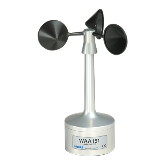
Page 10: Figure 1 Waa151 Anemometer
User's Guide ________________________________________________________ 0204-039 Figure 1 WAA151 Anemometer The following numbers refer to Figure 1 above: 1 = Cup wheel assembly 2 = Sensor shaft 3 = Lower body 8 ______________________________________________________ M210293en-A... -
Page 11: Chapter 3 Installation
Chapter 3 __________________________________________________ Installation CHAPTER 3 INSTALLATION This chapter provides you with information that is intended to help you install this product. Selecting Location Allow sufficient clearance for the wind sensors. Wind sensors should not be located next to a building or any other object that might affect the flow of air. -
Page 12: Installation Procedure
When the diagonal (W) is less than the height (H) the minimum length of the mast is 1.5 × W. Installation Procedure Mounting Sensor installation is most convenient when you use a Vaisala manufactured cross arm for mounting the sensor. 10 _____________________________________________________ M210293en-A... -
Page 13: Figure 4 Mounting Of Wind Sensor
Chapter 3 __________________________________________________ Installation Always mount the WAA151 Anemometer to the southern end of the cross arm. It is recommended that you remove the cup assembly to ease installation. Fit the 6-pin cable plug through the mounting flange at the end of the cross arm, then connect it to the sensor. -
Page 14: Alignment
If your sensor is connected to the data collection system and powered up, check that the speed readings are changing when you rotate the cup wheel manually. Connector The connector for the WAA151 is shown in Figure 5 below. 0002-027 Figure 5 WAA151 Connector The following letters refer to Figure 5 above. - Page 15 Chapter 3 __________________________________________________ Installation The heating element in the shaft tunnel is connected between pins D and E. You can supply the heating element with 20 VDC or VAC. The recommended cable connector for the sensor is SOURIAU MS3116F10-6P. VAISALA__________________________________________________________13...
- Page 16 User's Guide ________________________________________________________ This page intentionally left blank. 14 _____________________________________________________ M210293en-A...
-
Page 17: Chapter 4 Maintenance
Chapter 4 ________________________________________________ Maintenance CHAPTER 4 MAINTENANCE This chapter provides information that is needed in the basic maintenance of the WAA151 Anemometer. Periodic Maintenance Cleaning Heavy contamination in the cups, such as bird dropplets or ice will deteriorate the accuracy of the anemometer. Clean the cups when necessary. -
Page 18: Replacing Consumables
User's Guide ________________________________________________________ Replacing Consumables Replacement of the bearings should only be done by a trained technician. To replace the ball bearings, follow the procedure below and refer to Figure 6 on page 19. Open the cup wheel fixing screw with a 2-mm Allen key. - Page 19 Chapter 4 ________________________________________________ Maintenance 10. Remove the internal retaining ring at the bottom of the shaft (using narrow-pointed pliers). 11. Remove the lower bearing. 12. Push out the shaft downwards through the upper body. 13. Remove the top bearing after pulling out the shaft. To reassemble the sensor, reverse the above work order .
- Page 20 User's Guide ________________________________________________________ When placing the lower body assembly, make sure that the NOTE O-ring is correctly positioned between the upper and lower bodies. It is recommended to replace the O-rings with a new ones before reassembling. Tighten the hexagon nut of the connector (2). Connect the cable plug to the sensor body connector.
-
Page 21: Figure 6 Waa151 Assembly
Chapter 4 ________________________________________________ Maintenance 0204-043 Figure 6 WAA151 Assembly VAISALA__________________________________________________________19... -
Page 22: Parts List For Consumables
User's Guide ________________________________________________________ Parts List for Consumables Table 3 Available Spare Parts Spare Part Order Code Cup assembly 7150WA Set of bearings and gasket 16644WA Sensor board (PCB) 1433WA 20 _____________________________________________________ M210293en-A... -
Page 23: Chapter 5 Troubleshooting
The sensor is not powered Check that the supply voltage properly. is from 9.5 to15.5 VDC Some Vaisala products, for Check that the sensor output example, WAT12, switch rises above (U in - 1.5 V) at the power on to the sensor only end of the power pulse. -
Page 24: Getting Help
User's Guide ________________________________________________________ Problem Probable Cause Remedy The sensor shaft is The heating element does not Send the sensor to Vaisala for covered with ice function. repair. See section Return and snow. Instructions on page 23 for details. The heating element is not Open the sensor and check properly connected. -
Page 25: Return Instructions
Pack the faulty product using an ESD protection bag of good quality with proper cushioning material in a strong box of adequate size. Please include the Problem Report in the same box. Send the box to: Vaisala Oyj SSD Service Vanha Nurmijärventie 21 FIN-01670 Vantaa Finland... - Page 26 User's Guide ________________________________________________________ This page intentionally left blank. 24 _____________________________________________________ M210293en-A...
-
Page 27: Chapter 6 Technical Data
Chapter 6 _______________________________________________Technical Data CHAPTER 6 TECHNICAL DATA This chapter provides the technical data of the WAA151 Anemometer. Specifications Table 5 WAA151 Anemometer Specifications Property Description/Value Sensor/Transducer type Cup anemometer/Opto-chopper Measuring range 0.4 ... 75 m/s Starting threshold < 0.5 m/s Distance constant 2.0 m... -
Page 28: Mtbf
User's Guide ________________________________________________________ Property Description/Value Recommended SOURIAU MS3116F10-6P connector at cable end -50 ... +55 °C (with shaft heating) Operating temperature -60 ... +70 °C Storage temperature Housing material AlMgSi, gray anodized Cup material PA, reinforced with carbon fiber Dimensions 240 (h) ×... - Page 29 *M210293EN*...
Need help?
Do you have a question about the WAA151 and is the answer not in the manual?
Questions and answers