Table of Contents
Advertisement
Quick Links
Advertisement
Table of Contents

Related Manuals for ATEN RS-232


Summary of Contents for ATEN RS-232
-
Page 2: Fcc Information
FCC Information This equipment has been tested and found to comply with the limits for a Class B digital device, pursuant to Part 15 of the FCC Rules. These limits are designed to provide reasonable protection against harmful interference in a residential installation. This equipment generates, uses and can radiate radio frequency energy, and if not installed and used in accordance with the instruction manual, may cause interference to radio communications. -
Page 3: Technical Support
Telephone Support International 886-2-8692-6959 China 86-10-5255-0110 Japan 81-3-5323-7178 Korea 82-2-467-6789 North America ATEN TECH 1-888-999-ATEN ATEN NJ 1-732-356-1703 United Kingdom 44-8448-158923 Technical Support For international online technical support – including troubleshooting, documentation, and software updates: http://support.aten.com For North American technical support:... -
Page 4: Package Contents
Copyright © 2001 ATEN International Co., Ltd. Manual Part No. PAPE-0194-100 Manual Date: 2010-03-26 ATEN and the ATEN logo are trademarks of ATEN International Co., Ltd. All rights reserved. All other trademarks are the property of their respective owners. - 4 -... - Page 5 Systems based on the RS-422 and RS-485 standards, on the other hand, are not subject to the RS-232 limitations because they utilize different voltage lines for the data and control signals. The IC-485AI Isolated Converter is a bidirectional converter that...
-
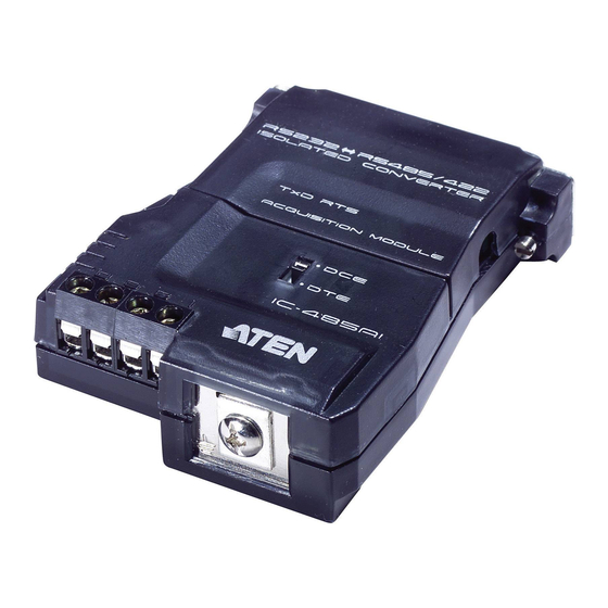
Page 6: Top View
If the IC-485AI is going to be plugged into a DTE device, the switch must be set to DCE, and vice versa. 5. Power Jack The cable from the Power Adapter plugs in here. 6. RS-232 DB-25 Female Connector - 6 -... -
Page 7: Bottom View
Bottom View: 1. DIP Switch This eight segment DIP Switch, located on the unit’s bottom panel, is used to configure the switch’s operating parameters. - 7 -... -
Page 8: Dip Switch Configuration
DIP Switch Configuration The IC-485AI’s settings for Baud Rate, Data Format, and RS-422 / RS-485 Mode are configured by setting the eight segment DIP Switch located on its bottom panel Note: When you change any of the DIP Switch settings, you must reset the device by powering it off, then powering it on again. - Page 9 SW 5-6: Data Format These two switch segments configure the bit settings for Start, Data, Parity, and Stop. Data Format (bits) Note: The default is 10 bits (1 Start; 8 Data; 0 Parity; 1 Stop). Unless you have a special reason to change this, we recommend that you leave it as is.
-
Page 10: Operating Modes
Operating Modes The IC-485AI supports three operating modes: Point-to-Point; Multidrop; and Simplex. Point-to-Point and Multidrop can be configured for Full or Half Duplex. Each of the operating modes is explained below. Point-to-Point A Point-to-Point configuration is one in which two devices, located at two different places are linked for communication by a pair of IC-485AI units. - Page 11 2. Point-to-Point 2 Wire Half Duplex Point-to-Point Half Duplex uses straight through two wire cabling, as shown in the diagram below. DB-25 DB-25 Connect Connect to PC#1’s to PC#2’s COM port COM port For both IC-485AI units, set the unit to DCE or DTE depending on what type of device the IC-485AI will plug into (if it will plug into a DCE device, configure it for DTE, and vice versa).
- Page 12 1. Multidrop Full Duplex Multidrop Full Duplex uses reverse four wire cabling, to link all the connected IC-485AI units: Slave 1 Master COM1/ COM1/ COM2 COM2 Slave 2 COM1/ COM2 Slave 31 For all IC-485AI units, set the unit to DCE or DTE depending on what type of device the IC-485AI will plug into (if it will plug into a DCE device, configure it for DTE, and vice versa).
- Page 13 2. Multidrop Half Duplex Multidrop Half Duplex uses reverse two wire cabling, to link all the connected IC-485AI units: Slave 1 Master COM1/ COM1/ COM2 COM2 Slave 2 COM1/ COM2 Slave 3 COM1/ COM2 Slave 31 For all IC-485AI units, set the unit to DCE or DTE depending on what type of device the IC-485AI will plug into (if it will plug into a DCE device, configure it for DTE, and vice versa).
- Page 14 Simplex A Simplex configuration is one in which more than two devices are linked for communication using several IC-485AI units in a manner similar to Multidrop. The difference is that in a Simplex configuration, the Master device can only talk, and the Slave devices can only listen.
-
Page 15: Installation
Installation 1. Make sure that all the devices you will be connecting up are powered off. 2. Set each IC-485AI’s configuration switches according to the information provided in the Switch Configuration and Operating Modes sections. 3. Plug the IC-485AI’s DB-25 female connector into the computer’s RS-232C port. - Page 16 RS-422 / RS-485 Installation Diagrams Slave 31 Master Slave 1 Slave 30 4,000’ RS-422 Full Duplex Note: When the distance between both ends of the installation is large and/or the transmitted signals are unstable, insert 120Ω terminal resistors between pins 1 and 2 and between pins 3 and 4 on the terminal blocks of the two units at each end of the installation.
-
Page 17: Terminal Block Pin Assignments
Appendix Terminal Block Pin Assignments DCE/DTE Transmit +V Transmit -V Receive -V Receive +V Circuit Test To test the IC-485AI’s internal circuits, connect a dumb terminal to the unit and do the following: 1. Set the DCE / DTE switch to the opposite of the terminal. 2. - Page 18 RS-485 Operation Mode Flow Charts RTS Control Mode Start RTS=0 Send Receive Receive RTS=1 Data Send Complete Data Complete The IC-485AI operates in RS-485 RTS Control Mode when both SW7 and SW8 are set to OFF. In this mode, RTS is pulled high when the computer makes a request to send data.
- Page 19 Auto Send Data Mode Start Busy Receiving Data CTS=1 Idle Receive CTS=0 Data Data Complete to Send Send Data Complete The IC-485AI operaties in RS-485 Auto Send Data Mode when SW7 is set to OFF, and SW8 is set to ON. In this mode, the status of the bus line is auto-detected in order to prevent more than one signal on the line.
- Page 20 DCE / DTE Connection Description Device’s Connector Pin # Cable IC-485AI 25/25 or 9/25 pin DB-25 DB-25 DB-9 DB-9 DB-25 DB-25 (PG) (DSR) (CD) (SCD) (SCS) (STD) (TC) (SRD) (RC) (SRS) (DTR) (SQD) (RI) (DRS) (XTC) - 20 -...
-
Page 21: Specifications
DC 9V; 900mW (max.) Data Rate Up to 115.2 Kbps under 1200 m (4000 ft.) Connectors 1 x DB-25 female (RS-232); 1 x 4 Post Terminal Block (RS-422 / RS-485); 1 x Grounding Tab Function Slide Switch DCE / DTE Select... -
Page 22: Troubleshooting
Troubleshooting Symptom Action Data Transmission Check that IC-485AI units are securely plugged into the computers’ serial ports. Failure Check that the cables are properly set up and properly connected. Check that SW1 and the DIP Switch are set properly. Insert terminal resistors according to the information given on p.
Need help?
Do you have a question about the RS-232 and is the answer not in the manual?
Questions and answers