Advertisement
Quick Links
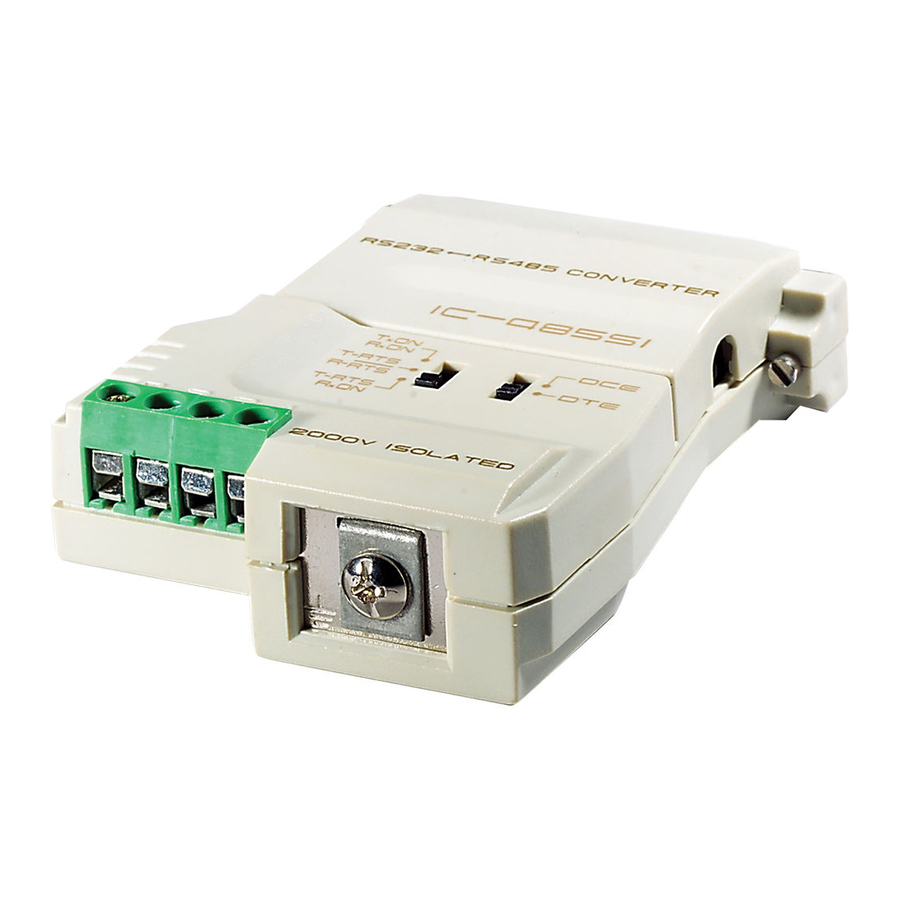
RS-232 To RS-485
Interface Converter
IC-485S / IC-485SI
User Manual
Read this manual thoroughly and follow the installation procedures carefully to
prevent any damage to the IC-485S / IC-485SI and/or the devices it connects to.
©Copyright 1998-2000 Aten® International Co., Ltd.
Manual Part No. PAPE-1134-100
Printed in Taiwan 01/1999
All brand names and trademarks are the registered property of their respective owners.
Packing Checklist
1 x IC-485S or IC-485SI Interface Converter
1 x Power Adapter (DC9V, 200mA)
1 x User Manual
1 of 10
Advertisement

Related Manuals for ATEN IC-485S


Summary of Contents for ATEN IC-485S
- Page 1 IC-485S / IC-485SI User Manual Read this manual thoroughly and follow the installation procedures carefully to prevent any damage to the IC-485S / IC-485SI and/or the devices it connects to. ©Copyright 1998-2000 Aten® International Co., Ltd. Manual Part No. PAPE-1134-100 Printed in Taiwan 01/1999 All brand names and trademarks are the registered property of their respective owners.
-
Page 2: Switch Configuration
RS-485 signals (and vice versa). The IC-485S / IC-485SI provides Point-to-Point; Multidrop; and Simplex operations over distances of up to 1200 m (4000 ft.). The IC-485S also provides a Monitor operation. Thus, they permitt the creation of reliable long distance data communications systems using standard computer hardware. - Page 3 SW1 is used to select the Device Mode SW2 is used to select the Transmitting and Receiving Mode IC-485S Position TxON, RxON TxRTS, RxRTS Monitor TxTRS, RxON IC-485SI 3 of 10...
-
Page 4: Operating Modes
RTS signal is high. Operating Modes The IC-485S / IC-485SI supports four operating modes: Point-to-Point; Multidrop; Simplex; and Monitor (IC-485S only). Point-to-Point and Multidrop can be configured for Full or Half Duplex. Each of the operating modes is explained below. Point-to-Point A Point-to-Point configuration is one in which two devices, located at two different places are linked for communication by a pair of IC-485S / IC-485SI units. - Page 5 For both IC-485S / IC-485SI units, set SW1 to DCE or DTE depending on what type of device the IC-485S / IC-485SI will plug into (if it will plug into a DCE device, configure it for DTE, and vice versa).
- Page 6 For all IC-485S / IC-485SI units, set SW1 to DCE or DTE depending on what type of device the IC-485S / IC-485SI will plug into (if it will plug into a DCE device, configure it for DTE, and vice versa).
- Page 7 For all IC-485S / IC-485SI units, set SW1 to DCE or DTE depending on what type of device the IC-485S / IC-485SI will plug into (if it will plug into a DCE device, configure it for DTE, and vice versa).
-
Page 8: Installation
Switch Configuration Operating Modes sections. For the IC-485S, you may use either the RJ-11 telephone socket, or wire directly to the Terminal Block. (See the Terminal Block section for pin assigment details.) For the IC-485SI, you must ground the device by connecting a grounding wire from the Grounding Tab to the grounding source. - Page 9 Receiver +V Receiver 2 +V DCE / DTE Connection Table Because of the polarity of the communication signals, a DTE configured device must connect to a DCE configured device. The shaded area in the figure below is an example of a DTE to DCE connection: Self Test To test tthe internal circit of the interface converter, connect a dumb terminal to the unit and do the...
- Page 10 Check that the cables are properly set up and properly connected. Check that SW1 and SW2 are set properly. Data Loss or Error Check that the Data Rate and Data Format are the same for all devices. Limited Warranty IN NO EVENT SHALL THE DIRECT VENDOR S LIABILITY EXCEED THE PRICE PAID FOR THE PRODUCT FORM DIRECT, INDIRECT, SPECIAL, INCIDENTAL, OR CONSEQUENTIAL DAMAGES RESULTING FROM THE USE OF THE PRODUCT, DISK, OR ITS DOCUMENTATION.
Need help?
Do you have a question about the IC-485S and is the answer not in the manual?
Questions and answers