Advertisement
Quick Links
Read this guide thoroughly and follow the installation and operation
procedures carefully in order to prevent any damage to the units
and/or any devices that connect to them.
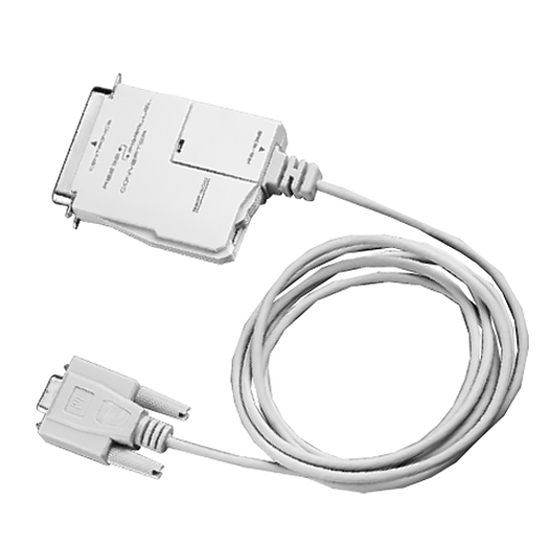
This package contains:
M 1 Bidirectional Serial/Parallel Converter (SXP-500)
M 1 User Manual
If anything is damaged or missing, contact your dealer.
© Copyright 2000 ATEN International Co., Ltd.
Manual Part No. PAPE-1154-100
Printed in Taiwan 10/1999
All brand names and trademarks are the registered property of their respective owners.
2001 - 01 -10
Advertisement

Related Manuals for ATEN SXP-500


Summary of Contents for ATEN SXP-500
- Page 1 This package contains: M 1 Bidirectional Serial/Parallel Converter (SXP-500) M 1 User Manual If anything is damaged or missing, contact your dealer.
- Page 2 The SXP-500 is an interface converter that allows Centronics and RS-232 devices to communicate with each other (a computer with an RS-232 output to a Centronics printer, for example) The SXP-500 provides a DB-9 RS-232C (DCE) compatible connector, and a C-36 Centronics connector. The serial baud rate is from 1200 to 115200 bps., selectable by a combination of DIP Switch and Jumper settings.
- Page 3 The SXP-500 is configured by setting an eight segment DIP Switch as follows: Switch Purpose Baud rate Setting Handshake Setting Data and Stop Bits Setting Parity Setting Conversion Direction setting An explanation of each DIP Switch setting is given in the next section.
- Page 4 Baud Rate: The baud rate is set with DIP Switch segments 1 - 3 (located on the bottom panel), and JP1 (located inside the housing), as shown in the table, below: DIP Switch Segment Baud Rate (bps) JP1 Short JP1 Open 1200 38400 2400...
- Page 5 3. Plug the male end of the C-36 male/female printer cable into the printer. Note: If the distance to the printer is close enough, you can plug the SXP-500 directly into the printer, without the need for a printer cable. - 4 -...
- Page 6 2. Use a serial cable with a male D9 connector at one end, and a male D25 connector at the other: a) Plug the D9 end of the cable into the SXP-500’s attached serial cable. b) Plug the D25 end of the serial cable into the printer’s serial port.
- Page 7 - 6 - 2001 - 01 -10...
- Page 8 When operating the SXP-500, please take note of the following: 1. Since the SXP-500 is a DCE device, the serial device it connects to must be configured as a DTE device. 2. In DCE mode, the unit uses RTS/DTR (pins 6 and 8) handshaking.
- Page 9 The RS-232C Interface DCE mode (default) specification is given in the table below: Name Function PULL Up (+9v) Transmit Data Receive Data Data Set Ready Ground Data Terminal Ready Clear to Send Request to Send Ring indicator - 8 - 2001 - 01 -10...
- Page 10 Name Function DATA STROBE DATA BIT 1 DATA BUS DATA BIT 2 DATA BIT 3 DATA BIT 4 DATA BIT 5 DATA BIT 6 DATA BIT 7 DATA BIT 8 DATA RECEIVED ACKNOWLEDGE BUSY DEVICE BUSY OR NOT PAPER EMPTY PULL UP SLCT PULL UP...
- Page 11 Symptom Possible Cause Action Power LED does Cables are not properly Make sure that all cables are properly not light plugged in. plugged in and fully seated in their connectors. No Data Transmis- Cables are not properly Make sure that all cables are properly sion plugged in.
- Page 12 WARNING!!! This equipment generates, uses and can radiate radio frequency energy and, if not installed and used in accordance with the instruction manual, may cause interference to radio communications. This equipment has been tested and found to comply with the limits for a Class B computing device pursuant to Subpart J of Part 15 of FCC Rules, which are designed to provide reasonable protection against such interference when operated in a commercial environment.
Need help?
Do you have a question about the SXP-500 and is the answer not in the manual?
Questions and answers