Table of Contents
Advertisement
Quick Links
Advertisement
Table of Contents

Related Manuals for Patton electronics 1092RC


Summary of Contents for Patton electronics 1092RC
- Page 1 USER MANUAL MODEL 1092RC High Speed, 2-Wire, Synchronous and Asynchronous Rack Mount Modem Card Part# 07M1092RC-E SALES OFFICE Doc# 033021U, (301) 975-1000 Rev. F TECHNICAL SUPPORT Revised 1/22/08 C E R T I F I E D (301) 975-1007 An ISO-9001 http://www.patton.com...
-
Page 2: Table Of Contents
4.0 Installation ................24 4.1 The Model 1000R16P Rack Chassis 4.1.1 The Rack Power Supply 4.2 Installing the Model 1092RC Series Into Chassis 4.3.1 Connecting to a “DTE” Device 4.3.2 Connecting to a “DCE” Device 4.3.3 Connecting the Twisted Pair Interface 4.3 Wiring the Model 1092RC Series... -
Page 3: Warranty Information
The Model 1092RC has been tested and found to comply with the limits for a Class A computing device in accordance... - Page 4 NOTE: Packages received without an RMA number will not be accepted. Patton Electronics' technical staff is also available to answer any questions that might arise concerning the installation or use of your Model 1092RC. Technical Service hours: 8AM to 5PM EST, Monday through Friday.
-
Page 5: General Information
(8 km) over one or two twisted pair (2 or 4 Wire). Supporting synchronous speeds up to 128 kbps and asynchronous speeds up to 38.4 kbps, the 1092RC is perfect for LAN interconnection or high speed internet links. Supporting 2B1Q encoding, Automatic Equalization and Auto Gain Control, the Model 1092RC compensates for poor line quality. -
Page 6: Configuration
“ON” and “OFF” positions. Front Panel 1 2 3 4 5 6 7 8 Figure 2. Close up of configuration switches (both sets are identical in appearance) NOTE: The ON position is oriented toward the front of the Model 1092RC. -
Page 7: Reversible Interface Driver Board
With the 1092RC pulled out of the rack or clusterbox chassis, locate the driver board on the top of the 1092RC front card. Lift the interface board gently off of the PC board. Locate the correct interface on the bottom of the driver board. -
Page 8: Configuration Switch Set "S1
S1-7 Tx Clock Source Switches S1-1 and S1-2: Data Rate Use Switches S1-1and S1-2 to configure the data rate of the Model 1092RC. Each setting represents one synchronous data rate and one asynchronous data rate. S1-1 S1-2 Sync Data Rate... - Page 9 Switch S1-3: Data Set Ready During Local Line Loopback Test Use Switch S1-3 to control the behavior of the DSR signal at the EIA interface during the local line loopback test. S1-3 Setting Description Enabled DSR is on during local line loop (default) Disabled DSR is off during local...
- Page 10 The Model 1092RC may be configured by a menu-driven software system when used with the Patton Model 1000CC (for ordering information, see Appendix B). In order to configure the Model 1092RC by software commands, you must set its control port address.
- Page 11 Switches S2-1, S2-2, S2-3, S2-4: Control Port Address -- LSD Use Switches S2-1, S2-2, S2-3 and S2-4 to set the least significant digit of the the Model 1092RC control port address. For example, using the table above, if the desired address is “63”, the “3” is the least significant digit in the address, set Switches S2-1, S2-2, S2-3 and S2-4 to OFF OFF ON ON, respectively.
-
Page 12: Configuring The Software Switches
The Model 1092RC features a menu-driven command system that allows you to configure either the local or remote 1092RC. The software control port signals of the 1092RC are carried to each card in the rack along the internal power bus board. Access to all rack card control ports is provided by a single PATTON Model 1000CC Control Card (see Model Model 1000CC User Manual). -
Page 13: Configuring The Local 1092Rc
3.2.1 Configuring the Local 1092RC To configure the local 1092RC, make a selection from the following MAIN MENU. To configure the remote 1092 or 1092RC, type [$] (Shift- 4) and refer to Section 3.2.2. MAIN MENU Option 1: Display Active Configuration Select Option 1 to display the most recent configuration of the local Model 1092RC (See below). - Page 14 1. DTE Rate Select Option 1 in the SOFTWARE CONFIGURATION menu to select the async. or sync. DTE Rate of the Model 1092RC. Different DTE Rate menu screens will display for async. or sync. bit rates. The selections are shown below.
- Page 15 Set this option as follows: Master Clock - Internal: Selection 1 allows the Model 1092RC to generate an internal clock as the timing source. Master Clock - External: Selection 2 allows the Model 1092RC to Derive the system clock from the locally connected DTE.
- Page 16 6. DTE Controlled Local Line Loop Select Option 6 in the SOFTWARE CONFIGURATION Menu to instruct the Model 1092RC to either respond or ignore Local Line Loop requests from the DTE. To instruct the Model 1092RC to respond to Local Line Loop requests from the DTE, select Enable (Option 1). To instruct the 1092RC to ignore Local Line Loop requests from the DTE interface, select Disable (Option 2).
- Page 17 Select Option 7 in the SOFTWARE CONFIGURATION Menu to enable DTE control of the Remote Digital Loop Menu (See below). The Remote Digital Loop on the 1092RC can be controlled from the DTE interface by selecting Enable (Option 1). To instruct the 1092RC to ignore this request from the DTE interface, select Disable (Option 2).
- Page 18 3.2.7 MAIN MENU Option 7: Test Modes Select Option 7 from the MAIN MENU to select the test mode status of the Model 1092RC. (below). The Model 1092RC Test Mode settings help to verify the integrity of the data link and isolate communication difficulties.
- Page 19 Test Mode options 2,3,7,8 and 9 require the 1092RC to be in Data Mode with the remote 1092RC. The Model 1092RC Test Modes are described below: Terminates all tests Initiates the built-in test pattern generator and detector. 511 with Errors Initiates the built-in test pattern generator and detector.
-
Page 20: Configuring The Remote 1092Rc
3.2.2 Configuring the Remote 1092RC To configure the remote 1092RC, make a selection from the following REMOTE UNIT CONFIGURATION MAIN MENU. To return to the LOCAL 1092RC MAIN MENU screen, press [ESC] and refer to Section 3.2.1. REMOTE UNIT CONFIGURATION MAIN MENU 1. - Page 21 REMOTE MAIN MENU Option 4: Display Hardware/Software Control Select REMOTE MAIN MENU Option 4 to select whether the remote Model 1092RC will use the hardware switch settings or the software switch settings for its active configuration. REMOTE MAIN MENU Option 5: Restart Remote Unit Select REMOTE MAIN MENU Option 5 to restart the remote unit.
-
Page 22: Configuring The Rear Interface Card
Figure 4. Model 1092RC Series interface card options NOTE: The 1092RC Series rear cards are specifically designed to operate with the Model 1092RC function card and must not be swapped with other Patton function cards. Prior to installation, you will need to examine the rear card you have selected and make sure it is properly configured for your application. -
Page 23: Model 1000Rcm12592 Strap Settings
3.3.1 Model 1000RCM12592 Strap Settings Figure 6 shows strap locations for the Model 1000RCM12592 (DB-25/RJ-45S) rear cards. These straps determine various grounding characteristics for the terminal interface and twisted pair lines. JB3 and JB4 are user configurable. JB2 must be set on pegs 1 and 2. Figure 6. -
Page 24: Model 1000Rcm13492 Strap Settings
SGND & FRGND (JB4) In the connected position, this strap links DB-25 pin 7 (Signal Ground) and frame ground. In the open position, pin 1 is disconnected from frame ground. Position 1&2 = SGND (Pin 7) and FRGND Connected Position 2&3 = SGND (Pin 7) and FRGND Not Connected 3.3.2 Model 1000RCM13492 Strap Settings Figure 7 shows the strap location for the Model 1000RCM13492 (M/34/RJ-45) rear card. -
Page 25: Installation
4.0 INSTALLATION This section describes the functions of the Model 1000R16 rack chassis, tells how to install front and rear Model 1092RC Series cards into the chassis, and how to connect to the twisted pair interface and the serial interface. -
Page 26: Installing The Model 1092Rc Series Into Chassis
4.2 INSTALLING THE MODEL 1092RC SERIES INTO THE CHASSIS The Model 1092RC Series is comprised of a front card and a rear card. The two cards meet inside the rack chassis and plug into each other by way of mating 50 pin card edge connectors. Use the following... - Page 27 4.3.1 Connection to a “DTE” Device Regardless of the interface module you choose, the Model 1092RC’s serial port is always wired as a DCE. Therefore it “wants” to plug into a DTE such as a terminal, PC or host. When making the...
- Page 28 RING Notice! Any modular twisted pair cable connected to the Model 1092RC must be shielded cable, and the outer shield must be properly terminated to a shielded modular plug on both ends of the cable. 4.3.5 Connection to the Control Port Interface Please refer to the Model 1000CC Control Card user manual for cable requirements of the Control Port Interface.
-
Page 29: Operation
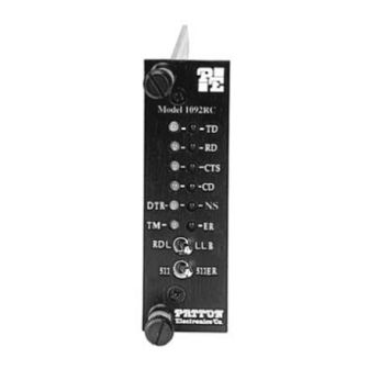
5.0 OPERATION Once the Model 1092RC is properly configured and installed, it should operate transparently. This sections describes functions of the LED status indicators, and the use of the built-in loopback test modes. 5.1 LED STATUS INDICATORS The Model 1092RC features twelve front panel LEDs that monitor power, the DTE signals, network connection and test modes. -
Page 30: Test Modes
The Local Line Loopback (LLB) test checks the operation of the local Model 1092RC, and is performed separately on each unit. Any data sent to the local Model 1092RC in this test mode will be echoed (returned) back to the user device (see Figure 11, below). For example, characters typed on the keyboard of a terminal will appear on the terminal screen. -
Page 31: Using Remote Digital Loopback (Rdl)
The Remote Digital Loopback (RDL) test checks the performance of both the local and remote Model 1092RCs, and the communication link between them. Any characters sent to the remote Model 1092RC in this test mode will be returned back to the originating device (see Figure 12, below). -
Page 32: Using The
Model 1092RC, and one to do the same at the remote Model 1092RC. In this case, the test pattern sent by each Model 1092RC will not be looped back, but will be transmitted down the line to the other... -
Page 33: Appendix A - Specifications
APPENDIX A PATTON MODEL 1092RC SPECIFICATIONS Transmission Format: Synchronous or asynchronous Transmission Line: Single unconditioned twisted pair Clocking: Internal, external or receive recover Distance: Up to 10.8 miles (17.3Km), all data rates, 19 AWG (.9mm) Up to 7.2 miles (11.5Km), all data rates, 22 AWG (.6mm) -
Page 34: Appendix B - Factory Replacement Parts And Accessories
APPENDIX B PATTON MODEL 1092RC FACTORY REPLACEMENT PARTS AND ACCESSORIES Patton Model # Description 1000RCM12592..Rear card w/DB25F & RJ45 (V.24 interface) 1000RCM12492..Rear card w/ M/34F & RJ45 (V.35 interface) 1000RPEM ....120/240V Rear Power Entry Module 1000RPSM-2 .....120/240V Front Power Supply Module 1000RPEM-DC ..DC Rear Power Entry Module... -
Page 35: Appendix C - Terminal Interface Pin Assignments
APPENDIX C MODEL 1092RC TERMINAL INTERFACE PIN ASSIGNMENT M/34F Connector-DCE (V.35 Interface) Pin # Signal B ......SGND (Signal Ground) C ......RTS (Request to Send) D ......CTS (Clear to Send) E ......DSR (Data Set Ready) F......CD (Carrier Detect) H ......DTR (Data Transfer Ready) ........ - Page 36 APPENDIX C (Continued) PATTON MODEL 1092RC TERMINAL INTERFACE PIN ASSIGNMENT DB-25F Connector-DCE (RS-232 Interface) Pin # Signal 1......FG (Frame Ground) 2......TD (Transmit Data) 3......RD (Receive Data) 4......RTS (Request to Send) 5......CTS (Clear to Send) 6......DSR (Data Transfer Rate) 7......SGND (Signal Ground) 15......TC (Test Control-A)
-
Page 37: Appendix D - Control Port Pin Assignments
APPENDIX D PATTON MODEL 1092RC CONTROL PORT PIN ASSIGNMENT (RJ-45 CONNECTOR ON 1000CC CARD) Pin Function RJ-45 Pin Number Transmit data (from DTE)........7 Receive date (to DTE)........6 Ground.............5... -
Page 38: Appendix E - Line Interface Pin Assignments
APPENDIX E LINE INTERFACE PIN ASSIGNMENT (RJ45 Connector) Pin Number Signal 1...........N/C (No Connection) 2...........N/C (No Connection) 3...........N/C (No Connection) 4...........Tip 5............Ring 6............N/C (No Connection) 7............N/C (No Connection) 8............N/C (No Connection) © Copyright 1997 Patton Electronics Company All Rights Reserved... - Page 40 Dear Valued Customer, Thank you for purchasing Patton Electronics products! We do appreciate your business. I trust that you find this user manual helpful. We manufacture one of the widest selections of data communications products in the world including CSU/DSU's, network termination units, powered and self-powered short range modems, fiber optic modems, interface converters, baluns, electronic data switches, data-line surge protectors, multiplexers, transceivers, hubs, print servers and much more.
Need help?
Do you have a question about the 1092RC and is the answer not in the manual?
Questions and answers