Table of Contents
Advertisement
Quick Links
Advertisement
Table of Contents

Summary of Contents for Patton electronics 1018RC
-
Page 1: User Manual
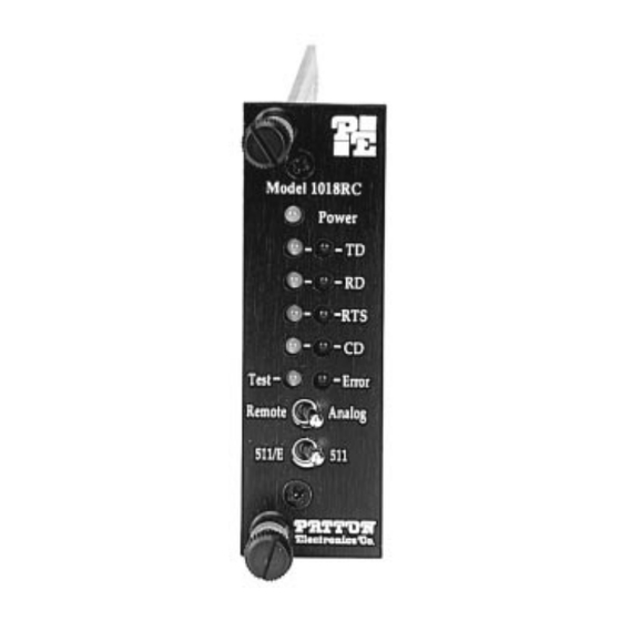
USER MANUAL MODEL 1018RC Powered High Speed Short Range Modem: Rack Mount Card SALES OFFICE Part# 07M1018RC-C Doc# 013012UC (301) 975-1000 Revised 2/4/97 TECHNICAL SUPPORT C E R T I F I E D (301) 975-1007 An ISO-9001 http://www.patton.com Certified Company... -
Page 2: Warranty Information
The Model 1018RC has been tested and found to comply with the limits for a Class A computing device in accordance... -
Page 3: General Information
3.1 FUNCTION CARD CONFIGURATION The Model 1018RC front card has two sets of eight switches (S1 & S2), which are mounted on the PC board (Figure 1, below). These configuration switches allow you to configure the Model 1018RC for a wide range of applications. -
Page 4: Configuration Switch Set "S2"
Figure 3. Summary of DIP switch default settings for set S1 S1-1: DTE Control of LAL The setting for switch S1-7 determines whether the Local Analog Loopback test on the Model 1018RC can be activated via pin 18 of the RS-232 interface. S1-1... -
Page 5: Configuration Jumpers
DB-25 F RJ-45 (8-wire) Figure 5. Model 1018RC interface card options Each of the four rear card options for the Model 1018RC has a distinct model number. The four options and their model numbers are shown on the following page. -
Page 6: Sgnd & Frgnd (Jb4)
Interface Combination Model Number DB-25 & RJ-11 1000RCM12511 DB-25 & RJ-45 1000RCM12545 RJ-11 & RJ-45 1000RCM1D11 Dual RJ-45 1000RCM1D45 Prior to installation, you will need to examine the rear card you have selected and make sure it is properly configured for your application. -
Page 7: Installation
4.0 INSTALLATION This section describes the functions of the Model 1000R16 rack chassis, tells how to install front and rear Model 1018RC cards into the chassis, and provides diagrams for wiring the interface connections correctly. 4.1 THE MODEL 1000R16 RACK CHASSIS The Model 1000R16 Rack Chassis (Figure 9) has sixteen short range modem card slots, plus its own power supply. - Page 8 Appendix D of this manual. The EIA-561 versions of the Model 1018RC use a 10 pin RJ-45 to connect the terminal interface to your computing hardware. It is pinned according to the EIA-561 DCE interface standard. For specific interface pin-outs, please refer to the diagram in Appendix D of this manual.
-
Page 9: Operation
The Local Analog Loopback (LAL) test checks the operation of the local Model 1018RC, and is performed separately on each unit. Any data sent to the local Model 1018RC in this test mode will be echoed (returned) back to the user device. For example, characters typed on the keyboard of a terminal will appear on the terminal screen. - Page 10 The Model 1018RC's V.52 BER test can be used independent of the V.54 loopback tests. This requires two operators: one to initiate and monitor the test at both the local and the remote Model 1018RC. To use the V.52 BER test by itself, both operators should...
- Page 11 APPENDIX B PATTON MODEL 1018RC CABLE RECOMMENDATIONS The Patton Model 1018RC operates at frequencies of 40kHz or less and has been performance tested by Patton technicians using twisted- pair cable with the following characteristics: Wire Gauge Capacitance 19 AWG 83nf/mi or 15.72 pf/ft.
-
Page 12: Interface Standards
APPENDIX D PATTON MODEL 1018RC INTERFACE STANDARDS DIRECTION STANDARD RS-232C/V.24 “DCE” SETTING 1- (FG) Frame Ground 2- (TD) Transmit Data 3- (RD) Receive Data 4- (RTS) Request to Send 5- (CTS) Clear to Send To 1018RC Analog Loop - 18...


Need help?
Do you have a question about the 1018RC and is the answer not in the manual?
Questions and answers