Table of Contents
Advertisement
Quick Links
Advertisement
Table of Contents

Related Manuals for Patton electronics 1110RC


Summary of Contents for Patton electronics 1110RC
- Page 1 USER MANUAL MODEL 1110RC Asynchronous, RS-232 Fiber Optic Rack Card Modem SALES OFFICE Part #07M1110RC Doc #018021U, (301) 975-1000 Rev. D TECHNICAL SUPPORT Revised 1/22/08 C E R T I F I E D (301) 975-1007 An ISO-9001 http:www.patton.com Certified Company...
-
Page 2: Radio And Tv Interference
The Model 1110RC has been tested and found to comply with the limits for a Class A computing device in accordance... - Page 3 NOTE: Packages received without an RMA number will not be accepted. Patton Electronics' technical staff is also available to answer any questions that might arise concerning the installation or use of your Model 1110RC. Technical Service hours: 8AM to 5PM EST, Monday through Friday.
-
Page 4: General Information
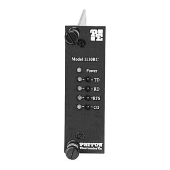
“Controlled by RTS”. Four pairs of bi-level LED indicators monitor TD, RD, RTS and CD. A single LED monitors power. The Model 1110RC is designed to mount in Patton’s 2U high 19” rack chassis. This 16-card chassis has a switchable 120/240 volt power supply and mounts cards in a mid-plane architecture: The front “brains”... - Page 5 Figure 1. Model 1110RC front card jumper locations JP1 and JP2: RTS/CTS Delay The combined settings for jumpers JP1 and JP2 determine the amount of delay between the time the Model 1110RC “sees” RTS and when it sends CTS. Setting...
- Page 6 3.2 REAR CARD SETTINGS The Model 1110RC is compatible with two dual-fiber interface cards, one with dual ST connectors and one with dual SMA connectors. Both cards use an HD-26 female for the RS-232 interface. The jumpers on both interface cards function identically. Figure 2 (below) shows the location of the jumpers.
- Page 7 DTE Shield (Pin 1) & FRGND (JB1) In the connected (closed) position, this strap links DB-25 pin 1 and frame ground. In the open (disconnected) position, pin 1 is “lifted” from frame ground. Position 1&2 = DTE Shield (Pin 1) and FRGND connected Position 2&3 = DTE Shield (Pin 1) and FRGND not connected...
-
Page 8: Installation
4.0 INSTALLATION This section describes the functions of the Model 1000R16 rack chassis, tells how to install front and rear Model 1110RC cards into the chassis, and provides instructions for connecting the interface cables. 4.1 THE MODEL 1000R16 RACK CHASSIS The 1000R16 Rack Chassis (Figure 4, below) has sixteen short range modem card slots, plus its own power supply. - Page 9 4.2 INSTALLING THE MODEL 1110RC INTO THE CHASSIS The Model 1110RC is comprised of a front card and a rear card. The two cards meet inside the rack chassis and plug into each other via mating 50 pin card edge connectors. Use the following steps as a...
-
Page 10: Fiber Connections
4.3.1 RS-232 CONNECTION The RS-232 port on the rear card of the Model 1110RC is wired as a DCE, and uses a female HD-26 connector. The HD-26 is an alternate connector according to the EIA RS-232E specification, and the pin-out is the same as a standard DB-25. -
Page 11: Operation
The green “RTS” and “CD” indicators glow solid to show the control signal is on. The red “RTS” and “CD” indicators glow solid to show the control signal is off. When the 1110RC is connected to a DTE, RTS will glow green for an incoming signal on RS-232 pin 4. - Page 12 APPENDIX A MODEL 111ORC SPECIFICATIONS Transmission Line: Dual optical cable Transmission Mode: Asynchronous, half or full duplex, point-to- point Interfaces: EIA RS-232, CCITT V.24 Data Rates: 0 - 19.2 Kbps Distance: 2 miles over continuous fiber RTS/CTS Delay: Switch-selectable: No delay, 9.0 mS, 79.5 Receiver Sensitivity: -45 dBm Coupled Power Output: -30 to -36 dBm...
- Page 13 APPENDIX B FACTORY REPLACEMENT PARTS The Patton Model 1110RC rack system features interchangeable rear half cards, power cords/fuses for international various operating environments and other user-replaceable parts. Model numbers and descriptions for these parts are listed below: Patton Model # Description 1000RPEM......120/240V Rear Power Entry Module...
- Page 14 APPENDIX C MODEL 1110RC PIN CONFIGURATIONS UNIVERSAL D-26 INTERFACE (DCE WIRING) 8- (CD) Carrier Detect Data Terminal Ready - (20) 7- (SG) Signal Ground 6- (DSR) Data Set Ready 5- (CTS) Clear to Send 4- (RTS) Request to Send 3- (RD) Receive Data...
- Page 15 APPENDIX C MODEL 1110RC BLOCK DIAGRAM Copyright © Patton Electronics Company All Rights Reserved...
- Page 16 Dear Valued Customer, Thank you for purchasing Patton Electronics products! We do appreciate your business. I trust that you find this user manual helpful. We manufacture one of the widest selections of data communications products in the world including CSU/DSU's, network termination units, powered and self-powered short range modems, fiber optic modems, interface converters, baluns, electronic data switches, data-line surge protectors, multiplexers, transceivers, hubs, print servers and much more.
Need help?
Do you have a question about the 1110RC and is the answer not in the manual?
Questions and answers